
- About Us
- Information
-

The Author ensures that the research has been conducted responsibly and ethically with adherence to all relevant regulations. read more..
- For Authors
- For Reviewer
- Manuscript Guidelines
- Membership
- Publication Ethics
-
- Journals
- Reprints
- e-Books
- Videos
- Policies
- Contact Us
 COVID-19
- Submissions


Full Text
Research & Development in Material Science
Comprehensive Methodology for Soil Stabilisation
Gabriel Barbeta*
Professor of Ecoarchitecture, Director of Sustainable Construction Research at the University of Girona, Spain
*Corresponding author:Gabriel Barbeta, Director of Sustainable Construction Research at the University of Girona, Spain
Submission: November 20, 2025;Published: December 19, 2025

ISSN: 2576-8840 Volume 22 Issue 4
Abstract
A simple, complete and comprehensive method is proposed to build with soil in an effective and sustainable manner, to ensure the architectural benefits and durability sought, consistent with current standards of quality and control. This work stems directly from a doctoral thesis and vast experience in construction and research over thirty years, and from the latest results obtained from chemical stabilisations using enzymes, carob, Chelidonium majus and various limes. The method consists of applying the most efficient and optimal stabilization to each type of clay present, based on its physicochemical characteristics and the moisture content specific to the construction technique used. This involves characterizing the particle size through granulometry and sedimentometry, its crystallographic nature through thermal gravimetric analysis and/or X-ray diffraction, and testing its strength and shrinkage behavior with different stabilizers. Finally, a working table is presented showing the optimal stabilization methods for each type of clay present.
Keywords:Soil stabilisation; Clay; Earth construction; Soil cement; Rammed earth
Abbreviations:CEB: Compressed Earth Block; T: Tetrahedra Layer; O: Octahedral Layer
Introduction
When an architect sets out to design and build an earth structure - using local soil or material extracted from excavations and the foundation itself - they often find themselves disoriented and alone in deciding how to proceed. Numerous standards and standardised tests in the fields of geotechnics and construction provide us with data, but we need to know which are essential and how they correlate most effectively. Working methodologies, when consulted, tend to be limited to a specific soil type, technique, or stabilisation system - and they often avoid considering the crystallographic nature of the clays that actually bind the soil particles together.
This article also argues for the necessity of stabilising the soil to achieve the essential architectural performance required of any modern building material. Today, we have sufficient knowledge to construct earthen buildings resistant to flooding and earthquakes. The degree of improvement in water resistance, volumetric shrinkage and/or increased mechanical strength is determined by the chemical nature, particle size distribution and plasticity of the available soil. Reducing shrinkage, porosity and permeability allow for a general increase in mechanical properties and a reduction in sensitivity to water action - swelling and shrinkage, reduced cohesion and stiffness, erosion and frost shattering. Capillary water or rainwater, upon entering the binding structure of clays, breaks the weak van der Waals forces of surface tension in the interlayer water. Subsequently, it breaks the electrovalent bonds and, under certain alkaline or acidic conditions, even the strong covalent bonds. Therefore, it is essential to coat the material or to physically and chemically stabilise its structure to generate covalent and irreversible bonds. The stabiliser causes cation exchange and a transformation of the clay’s peripheral bonds. The soil structure changes, and a new structural matrix is physically formed, intermixed with new elements that reinforce it and improve its flexural strength.
Methodology
Local popular technology analysis
An analysis of local technologies and resources is necessary to understand existing experience and traditional knowledge regarding earthen materials. This will allow us to develop a type of local action better suited to native resources, the environment and existing sociocultural values - always in line with the global perspective of sustainable development. This focuses primarily on:
1) Locating local earthen constructions.
2) Visually identifying construction quality.
3) Detecting the presence of the ceramic industry, which uses
clays rich in illite and/or kaolin.
Analysis
A simple stabilisation method for any type of building soil should be based on knowledge of its clay mineralogical composition and certain laboratory and construction site data. Stabilisation involves modifying the soil’s composition physically and chemically to increase its durability and strength. The order of tests presented here is the simplest and most efficient for stabilising soil and obtaining a suitable building material, without overlooking the characteristics of the soil and the available stabilisers (Table 1).
Table 1:Sieved by weight %.

Analysis Methodology:
1. Particle size analysis - with washing and deflocculation to
remove silt and clay adhering to the aggregates.
2. Quantification of crystallographic types of clays present in
the soil - via X-ray diffraction and sedimentation (Brockville
method).
3. Shrinkage - 5x70cm box method.
4. Stabiliser determination
5. Performance verification - durability (six wetting-dryingfrost
cracking cycles); compressive and shear strength
Preliminary field assessment of organoleptic properties
The following aspects will be observed during sample
extraction:
a. Presence of a musty scent, particularly if the odour
intensifies when the soil is moistened or heated. Such soil will
be discarded.
b. Type of clay deposit, distinguishing between allochthonous
(transported) and autochthonous (formed in place); in
the latter case, and under sufficiently reducing conditions,
montmorillonite clays may be present.
c. Geological profile and soil layer depth, including rock types
or formations in the region and their erosion, slope stability,
potential landslides and microrelief formation. Highly stable,
compact and erosion-resistant slopes are favourable for the
use of the material in rammed earth and poorly stabilised
Compressed Earth Blocks (CEB).
d. Clay behaviour in water, including dispersion, colour, turbidity,
waterlogging, and the presence of expansive or fissurable clays
in puddles and flood-prone areas (Figure 1 & 2).
e. Texture and consistency, as determined by field tests (5-15cm
cylinder test, tongue test and tactile test): sand may or may not
be visible but is easily felt by hand. A sample with low moisture
content is easily compacted by hand (tap test) and becomes
plastic when moisture content increases.
f. Colour of the dried and sieved sample (<88μm), compared
with Figure 3, to help identify clay types and detect the presence
of iron sulphides, organic matter or oxides. Any specks or
inclusions should be identified as carbonates, iron, roots or
organic matter.
Figure 1:Clay colours.

Figure 2:Normalised granulometric curve.

Figure 3:ATD–ATG curves and first derivative for the main contrasting clay species: Ka. kaolinites, Mon. montmorillonite, and Ill. Illite.

Determination and evaluation of the granulometry curve
The determination of particle size distribution curves is carried out through the granulometric [1] and sedimentometric analysis of the various fractions defined by the maximum particle sizes. Thus, for the production of Compressed Earth Blocks (CEB), where the maximum aggregate size is below 10mm, only 500g of sample is required, which greatly facilitates the cleaning and settling of fines. The general granulometric criterion adopted for soil used in construction is that it should contain a clay proportion between 15% and 18%. However, if we increase the granulometric threshold to 5 microns - the fraction where the most strongly flocculated clays are found - we observe values between 21.1% and 24%. Silts appear in almost the same proportion, between 20% and 23%, as shown in the table below. It can also be noted that the limits established by Bolomey’s continuous parabola, intended to guarantee a lower pore index, are appropriate for coarse fractions. However, when applied to silts and clays, they diverge significantly from the limits previously adopted.
We compared this with the particle size analysis of several natural soils [2]. The results were highly variable, with the silt-toclay ratio ranging from 0.0091 and 0.4 up to 20.3. Even in seemingly identical soils, it fluctuated between 0.8 and 20.3. Despite this, 50% of the soils tested showed ratios approaching 1:1. Thus, the ideal silt-to-clay ratio is established as 1:1.
The silty and clayey particle size fraction (<80μm) is separated from the sands by decantation with distilled water, and some of the suspended particles are removed by absorption using a heated sodium-glass capillary tube. The solutions are then placed under an infrared lamp at 60 °C and 60% relative humidity to avoid disturbing the outermost atomic hydration layers, thus allowing for accurate readings by DAT or other physicochemical analyses. Drying is stopped when a solution with an approximate density of 1.050g/cm³ is obtained. Sedimentation analysis is then initiated to differentiate the fines using the Brockville method. The 1,000cm³ solution is stirred manually or mechanically at a rate of 1 to 3 cycles per second, and times, temperatures (20-25 °C is recommended) and readings from a calibrated and corrected sedimentation meter (adjusted for pressure, temperature and deflocculant use) are recorded. The ASTM Soil Hydrometer 152H model is recommended. The best way to take readings with this instrument is from above, noting the value at the top of the meniscus. The initial reading corresponds to the fine sand level; the remainder is silt and clay. Readings are then taken at 1, 2, 3, 4, 8 and 16 minutes (the point at which the clay fraction generally begins), followed by 30 and 60 minutes, 2 hours, 16 hours, 24 hours and finally at 48 hours. The Stokes formula D= K√L/t is used to calculate the size and amount of sedimented granulometric fraction at each instant [1-3].
Characterisation of the basic clays present in the sediment fraction
The main clay mineral species present in the soil are:
-Kaolinite (Nacrite, Dickite, Halloysite). Size ≈ 1μm. Consists of 100 layers 720μm thick, held together by hydrogen bonds between OH- groups of the Gibbsite layers and the oxygen atoms of the adjacent silicon layers (T+O), which do not dissociate upon contact with water. Cation exchange capacity: 2.2-15meq. It is non-expansive, has low plasticity and cohesion, and is difficult to disperse - even under acid attack. Thixotropic limit: 70-95g water/100g. Its light brown colour indicates high alumina content, low iron content, and 1% gypsum. Water content is 0.5% in a 5° layer, with a specific surface area of 10cm²/g. Kaolinite is a product of the weathering of orthoclase feldspar, derived from granite, and is typically found in sedimentary environments.
-Illite. . Size ≈ 0.1μm. Composition is similar to mica - sextuple layers (T+O+T, T+O+T) - and to xanthophyllite, but with lower potassium content (3-7%), higher combined water (5%) and reduced aluminium substitution (9-32%) by silica in the tetrahedral layer (38-53%). This is attributed to the low potassium content and partial disruption of the K+ alkali bond, part of which is replaced by Ca²⁺ and Mg²⁺. As a result, illite exhibits a high exchange capacity compared to micas (10-40meq) and a high silica index. It is expansive, with medium plasticity and low permeability. If sodic, it dissolves rapidly in water.
Thixotropic limit: 110-170g water/100g. Effervescence under acid attack indicates the presence of calcium or magnesium illite. Its colour ranges from creamy white, beige to earthy greenish-grey, with white streaking and an unctuous texture. Illite is typically associated with montmorillonite or kaolinite. It reacts slowly with lime and is completely inhibited in the presence of .
-Montmorillonite (nontronite; Fe-rich; Mg saponites with low Al; hectorites with Li; beidellite: low Si, Al-rich). Size ≈ 0.01μm. Triple-layer system O+T+O. Its structure is similar to Brucite and Gibbsite, but in the layers adjacent to these units there are only silica sheets, which lack external hydroxyl bonds. As a result, the units are linked by van der Waals forces. Montmorillonite is highly expansive, with high plasticity, sticky and soft texture, and very low permeability. It has a high cation exchange capacity (75-150meq, though limited with Mg and Al, as these elements are already part of the structure. According to the Emersson test, it shows the greatest dispersion in water. Thixotropic limit: 700-1350g water/100g. Effervescence under acid attack indicates calcic or magnesian montmorillonite. Its colour is greenish white, becoming much whiter when pulverised. Water content reaches 50% in a 5° layer, with a specific surface area of 1,000 cm2/g.
-Chl o r i te: 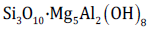 . Size ≈ 0.1μm. L ami n a t e d
structure of six layers, comprising two triple layers (T+O+T)
linked by an alkali ionic bridge via the K⁺ cation. This configuration
combines the charged basic unit of mica (talc) with the charged unit
of Brucite. Possible substitutions of Al for Si in the tetrahedral layer,
and Fe²⁺ or Fe³⁺ for Al in the octahedral layer. Chlorite exhibits low
expansiveness, low shear strength and elasticity, and is difficult to
disperse in water, even under acid attack. Its colour is bluish grey.
Cation exchange capacity: 10-40meq. It commonly associates with
Illites.
. Size ≈ 0.1μm. L ami n a t e d
structure of six layers, comprising two triple layers (T+O+T)
linked by an alkali ionic bridge via the K⁺ cation. This configuration
combines the charged basic unit of mica (talc) with the charged unit
of Brucite. Possible substitutions of Al for Si in the tetrahedral layer,
and Fe²⁺ or Fe³⁺ for Al in the octahedral layer. Chlorite exhibits low
expansiveness, low shear strength and elasticity, and is difficult to
disperse in water, even under acid attack. Its colour is bluish grey.
Cation exchange capacity: 10-40meq. It commonly associates with
Illites.
Clay content determination by ATD/ATG thermogravimetry or XRD diffraction
Thermogravimetric analysis (TGA) records the mass changes of a given material - whether in solid, amorphous or crystalline phase - as a function of temperature, relative to an inert reference. These results are summarised in Table 2, which highlights the thermal peaks observed, quantifies the corresponding mass losses, and links them to specific clay minerals or binding agents.
Table 2:Summary of endothermic peaks associated with elements identified in soil analyses.

For the mineralogical analysis of the clays, a Bruker D8 ADVANCE X-ray diffractometer with Advanced Geometry was also used, operating in Bragg-Brentano reflection mode with a θ-2θ configuration and CuKα radiation (λ = 1.5406Å) (Figure 4).
Figure 4:Bruker D8 ADVANCE X-ray diffractometer. Diffraction cell showing the X-ray monochromator (left) and the detector collecting the sample’s reflection (right).

The instrument operates across a range of diffraction angles (θ- 2θ) to capture reflections from multiple crystallographic planes, as minerals - particularly clays - exhibit several diffraction peaks of varying intensity. The typical basal spacings (d-values) for the three most common clay minerals are:
A. Kaolinite 7Å (semiquantitative calculation coefficient
0.14)
B. Illite 10Å (0.16)
C. Smectite 10-11Å (0.18)
In the case of kaolinite (always prepared as an oriented aggregate on glass) it is treated with Mg²⁺ (generally a 1M MgCl2 solution, where Mg²⁺, with a high hydration radius, tends to expand the lamellar layer) and the clay maintains a value of 7Å. The kaolinite is then treated with glycerol or ethylene glycol (which is chemically similar to monoethyl ether, an organic molecule with a large surface area that should force the clay to expand), but the kaolinite still maintains a value of 7Å. Subsequently, the kaolinite is treated with K⁺ (a 1M KCl solution, which should force the closure of the clay - in case it had expanded - since potassium has a low ionic potential and can be easily adsorbed by the clay) but the kaolinite again maintains a value of 7Å. The final treatment involves placing the clay sample (oriented aggregate) in an oven at 550 °C. In this case, the clay degrades, and when analysed by X-ray diffraction, it shows no diffraction signal. In this way, we have identified this clay as kaolinite.
The same occurs with illite, which maintains a constant value of 10Å throughout the treatments. With smectite, identification is more complicated because it initially shows a d-value of 10-11Å under normal conditions. After treatment with Mg²⁺, the d-value increases to 14 - 16Å; with glycerol it increases to 18Å; and when treated with K⁺, it closes to 12Å due to the action of this cation. Finally, after heating at 550 °C, the clay further closes at 10Å, as all hydration water has been lost and diffraction only detects the tetrahedral (2 x 2.4), octahedral (1 x 2.4) and lamellar (1 x 2) layers.
Identifying other types of clay can be even more complicated, as mixed or overlapping clay phases may require density separation treatments. When the clay phases show thin, clean and stylised peaks, this indicates high crystallinity.
Physical analyses. Evaluation of volumetric stability using the shrinkage test
Using a sample of clay with standardised plasticity, or with the moisture content specific to each technique (drop ball test for CEB-rammed earth) [4], a cubic test mould - preferably plastic or finely milled metal, 50cm long by 5cm wide and high - is filled. The mould is previously greased with oil. The sample is left to dry under laboratory conditions for seven days. After this period, drying is completed in an oven at 60 °C for 24 hours. The dry shrinkage value is determined by measuring the cracks in the prismatic soil sample and the separations from the mould. From this, two comparative values are obtained: the linear shrinkage, expressed as a percentage of shortening relative to length, and the type of cracking, evaluated by the number of cracks in the sample and the distance between them.
The presence of significant cracks will indicate (Figure 5), a priori, the need to repeat the test with already stabilised soil and verify compliance with the following linear shrinkage limits:
Figure 5:XRD diagram with the most representative profiles of the clays. Treatments: normal (black line), treated with ethylene glycol monoethyl ether (glycolate, red line), and heated to 550 ℃ (blue line).

Linear shrinkage of the stabilised rammed earth: <1.0mm/m
Linear shrinkage of the CEB wall: <3% (1).
Optimal stabiliser
Stabilisation is defined as a physical, physicochemical or chemical process that enables soil to respond satisfactorily and permanently to the demands imposed for its use in construction. Maintaining earth-rendered walls without protective covering is extremely difficult and costly.
This process - aimed at improving water resistance, reducing volumetric shrinkage and increasing mechanical strength - is determined by:
A. The chemical nature of the base soil, including its particle
size distribution and plasticity.
B. The desired improvements: with respect to the three
points above, although the authors of CRA Terre refer more
to reducing porosity - that is, the void volumes between solid
particles - than to shrinkage [5-13]:
C. The available products, materials or technological
processes.
D. The economic and environmental impact assessment.
E. Maintenance and usage conditions. Reducing shrinkage
or porosity, permeability and increasing mechanical resistance
allows for an overall improvement in mechanical characteristics
and a reduction in sensitivity to the action of water: swelling
and shrinkage, reduction of cohesion and rigidity qualities,
erosion and gelation. The method described here consists
essentially of selecting a stabiliser based on local resources, the
technique to be used and the characterisation of the soil and
clay types of present. In addition, chemical analysis using Dr
Ferran Gomà’s method [14], which assesses soluble fractions,
cation exchange capacity and pH, provides further identifying
data about the material. Activating as much soluble silica as
possible - whether from the soil itself or externally through
additives - is considered fundamental to the stabilisation
process. The increase in soluble silica enables the formation
of resistant HCS phases (hydrated calcium silicates), which
is associated with increased strength when using cements
and pozzolanic admixtures. This also occurs, although to a
lesser extent, with the HCA (hydrated calcium aluminates), SA
(sulfoaluminates) and FA (ferroaluminates) phases, generated
by gypsum, sulphates, aluminous cement, natural cements and
lime. Expression of the relationship between soluble silica and
strength:
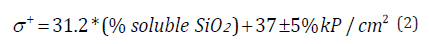
From there, the stabilisation table is consulted based on the clay’s mineralogical type to determine which stabilisers are likely to be most effective. In case of doubt, the best approach is to experimentally test all available stabilisers that appear to yield the best results. The stabilisation table is based on laboratory tests with pure clays conducted in several of our own studies [2,7,9,10,12].
In the final phase of the analytical method, the effectiveness of the stabilised mixture as a construction material must be verified. This involves assessing the strength and durability of various series of five test specimens, using the established stabilisers and proportions (Appendix A and B). Strength measurements - typically compressive and shear in seismic zones - will be performed using 4 x 4 x 4 cm RILEM-type micro-specimens, and ultimately, for final decision-making, with actual CEB specimens (Table 3 & Figure 6).
Table 3:

Figure 6:Shrinkage test on three soil samples for rammed earth.

Apendix A:

Apendix B:

Stabilisers
The sustainable selection criteria to be applied are summarised
in UNE Standard 41410, Annex C - whose drafting we contributed
to - and in reference [2]. These include:
a. Use of a local product.
b. Technological processes appropriate and adapted to the
sociocultural environment; it is essential to adopt a technology
that is simple to implement and readily assimilated by
developers and a workforce accustomed to conventional
architecture.
c. Economic evaluation.
d. Maintenance and use conditions.
Environmental impact must be minimised throughout the stabiliser’s life cycle assessment (LCA): minimal consumption of energy, water and non-renewable resources, and minimal emission of toxic substances into the environment during extraction, manufacturing, transport, application and throughout its useful life. An initial inventory of inputs and outputs is carried out, along with a comparison with other materials. The calculated values for CEB (stabilised compressed earth block) range from 0.4 to 0.82MJ/kg - a value three times lower than if the block were baked.
e. Curing, deflocculation and hardening factors derived from
the local climate.
f. Environmental and structural risks: frost, wind, temperature
fluctuations, risk of cracking, and curing conditions.
Simple and diagonal compressive strength
The defines the condition of the test specimen after immersion for four hours, followed by a flatness check of the faces without sulphur coating. Specimens are typically 10 x 10cm, but we continue to use 4 x 4cm RILEM specimens, tested at a loading rate of 1mm/ min (equivalent to 3/7kP/cm²s), which yields an average accuracy of approximately 6%. The tests are documented in Appendix A and B (Figure 7).
Figure 7:Compressive strength results using mini-specimens of pure clay samples [2].

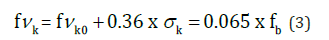
We have verified that the calculated strength of the masonry, when tested using diagonal compression on CEB specimens, approximates the formula established in the CTE (Spanish Technical Building Code):
Durability tests. absorption
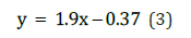
The first stage of the durability tests consists of saturating the test specimens in distilled water under laboratory conditions. To evaluate the most superficial capillary pores, an initial reading is taken one minute after immersion. Total saturation may also be estimated after 48 hours of immersion, although this step can be omitted due to the similarity of results observed in previous tests. Any method involving boiling has been discarded to avoid the pressure exerted by water currents and the resulting loss of sample integrity. There is an inversely proportional relationship between the percentage of absorption and the soluble silica content. The trend follows an exponential pattern, as expressed by the following equation: [2]
Cyclic Wetting-Freezing-Drying Test
The proposed durability evaluation method combines, in a single test, six cycles of freezing, wetting, drying and aggressive attack, including sulphate analysis in cases where stabilisation involves non-sulphur-resistant cements. The procedure is derived from ASTM D-559 and D-560, NLT-303-72 and UNE 7033 for freezing tests, and consists of 20 cycles alternating between 10 °C (one hour in water) and -15 °C (four hours).
Following the absorption test, specimens are dried in a muffle furnace at 60 °C for 48 hours. After this period, the specimens are brushed using a tool with a diameter equal to 50% of the surface area of the specimen faces, applying a pressure of 15N. This pressure is verified by placing the sample on the balance pan and applying the brush until a reading of 1.5kg is obtained. After the first wetting and drying cycle, a frost shattering (G) cycle is carried out at -15 °C for eight hours, followed by drying in an oven at 60 °C for the same duration to avoid structural alterations to the clays.
The third cycle consists of saline wetting (Ws) and drying (S). The sodium salt is dissolved to saturation under laboratory conditions. The fourth cycle combines saline wetting, frost shattering and drying in eight-hour periods. The aim is to exacerbate the expansive stresses caused by salt attack with those resulting from ice crystal formation.
Conclusion
Our 35 years of experience in the earth construction sector have enabled us to develop a more coherent and effective working method, and to share a summary of key findings. We highlight the considerable variation in the behaviour of clay samples when exposed to lime, specialised cements and gypsum. However, improvements in mixing and compaction water, the use of fluidisers and the application of mechanical pressure can be achieved without relying heavily on additives. From the interrelation of the results obtained using the described method, a direct relationship emerges between the crystallographic and chemical nature of the soil and its most effective stabilisation system. There is also a correlation between strength, void ratio e, degree of stabilisation %, the proportion of fines smaller than 0.4mm (modulus % M), and the liquid limit of the soil (Wl) (Figure 8).
Figure 8:Earth block shear test conducted at Girona University Laboratory [17].

Water resistance remains a critical factor - its limitations have historically undermined the viability of this construction method and contributed to its decline. This issue must be addressed with even greater urgency given the current scenario of increasingly extreme rainfall. Stabilisation methods that improve water resistance have, in some cases, led to reduced strength. Nonetheless, they are preferable and more durable than relying solely on external hydrophobic treatments. As research into new soil types and stabilisation methods continues, it is essential to interrelate the data to produce simpler yet more comprehensive working tables that integrate the scientific knowledge relevant to this construction material today.
References
- Standardised tests: UNE 103-101, UNE 41410, ASTM D422-63, NLT-104/72.
- Barbeta, Solà G (2002) Improving stabilized earth in the development of sustainable architecture for the 21st Polytechnic University of Catalonia, Spain.
- Houben H, Guilland H (1989) CRA Terre. Building on Earth.
- Neves C (2009) Soil selection and control methods in earth construction - Field Practices.
- Anger R, Fontaine L La terre (2008) Is it just another type of concrete? Some mechanisms for stabilizing earthen materials. In: Terra (Ed.), Proceedings of the 10th International Conference on the Study and Conservation of Earthen Architectural Heritage, Bamako, Mali. GCI Editions, Los Angeles, USA, pp. 222-225.
- Ferron A, Matero F (2008) The Consolidation of earthen surface finishes: Developing a protocol for treatment evaluation at Mesa Verde National Park. In: Terra (Ed.), Proceedings of the 10th International Conference on the Study and Conservation of Earthen Architectural Heritage, Bamako, Mali. GCI Editions, Los Angeles, USA, pp. 214-221.
- Clausell JR, Hidalgo C, Barbeta G (2020) Improvement in the rheological and mechanical properties of clay mortar after adding Ceratonia Siliqua L. Extracts. Construction and Building Materials 237: 117747.
- Villanueva Mena J (2018) Poured Soil: a study of deflocculants, fluidizers, and plasticizers as stabilizers to reduce water content. PFM. Master's thesis, Master in Applied Bioconstruction and Ecoarchitecture, University of Girona, Catalonia, Spain.
- Naqui E (2018) Study of clay stabilization based on the presence of activated waters and energy fields. PFM. Master’s thesis, Master in Applied Bioconstruction and Ecoarchitecture, Universitat de Girona, Catalonia, Spain.
- Carbonero A, Hormigo A (2017) Clay stabilisation using plant-based enzymes; PFG. DAEC, University of Girona, Spain.
- Firoozi AA, Olgun CG, Firoozi AA, Shojaei Baghini M (2017) Fundamentals of soil stabilization. International Journal of Geo-Engineering 8(26):
- Janer FX, Berthelsen B, Barbeta G (2014) Water-repellent stabilization for earth plasters with natural extracts. In: Earth Construction: Research and Documentation. XI CIATTI 2014 - Earth Architecture Congresses in Cuenca de Campos.
- Pascual R, Vinyoles X (2009) Study of shear and compressive strength in BTC masonry. PFG, University of Girona, Spain.
- Gomà FG, Vicente MD (1999) Chemical analysis of hardened concretes and mortars with active additions: A new procedure for their identification. In: Utilizing Ready Mix Concrete and Mortar - Proceedings of the International Conference Creating with Concrete and Mortar, RK Dhir, MC Limbachiya (Eds.), Thomas Telford Publishing, London.
© 2025 © Gabriel Barbeta. This is an open access article distributed under the terms of the Creative Commons Attribution License , which permits unrestricted use, distribution, and build upon your work non-commercially.
Editor In Chief


.jpg)


Signup for Newsletter

Quick Links
 Editorial Board Registrations
 Submit your Article
 Refer a Friend
 Advertise With Us
Our Recent Edition

.jpg)


Top Editors


.jpg)


.bmp)
.jpg)
.png)
.jpg)


.jpg)


.png)

.png)


.png)


Financial Support

Sponsors

Latest e-Books

Latest Video

 a Creative Commons Attribution 4.0 International License. Based on a work at www.crimsonpublishers.com.
Best viewed in
a Creative Commons Attribution 4.0 International License. Based on a work at www.crimsonpublishers.com.
Best viewed in