

- About Us
- Information
-

The Author ensures that the research has been conducted responsibly and ethically with adherence to all relevant regulations. read more..
- For Authors
- For Reviewer
- Manuscript Guidelines
- Membership
- Publication Ethics
-
- Journals
- Reprints
- e-Books
- Videos
- Policies
- Contact Us
 COVID-19
- Submissions



Full Text
Advancements in Civil Engineering & Technology
Enhancing Load Transfer of Piles in Thawing Permafrost with a Cryogenic Solution
Amirhossein Amanzadeh1 and Mohammad Rayhani2*
1 M.Sc., Research Associate, Geoengineering Research Group, Carleton University, Canada
2 Ph.D., Professor, Geoengineering Research Group, Carleton University, Canada
*Corresponding author:Mohammad Rayhani, Ph.D., Professor, Geoengineering Research Group, Carleton University, 1125 Colonel by Drive, Ottawa, K1S5B6, Canada
Submission: July 23, 2026;Published: August 18, 2026

ISSN: 2639-0574 Volume7 Issue 2
Abstract
Pile foundations are frequently employed in permafrost regions to support various infrastructure systems due to their robust load-bearing capabilities in frozen soils. However, these foundations are susceptible to diminished bearing capacity and higher displacements when subjected to warmer temperatures in permafrost areas. This paper introduces a research initiative aimed at devising a retrofitting method to increase the load carrying capacity of steel pile foundations in thawing permafrost regions. The primary objective was to re-establish frozen conditions in the thawed soil surrounding pile foundations and foster adfreeze bonding at the interface between the pile and the soil. The proposed refrigeration technique entails circulating a low-temperature freezing liquid (Antifreeze) within steel pile tubes to explore the feasibility of reducing the temperature of both the pile and its adjacent soil. Ideally, this process would induce freezing at the pile-soil interface, thus enhancing the load-bearing capacity of pile foundations in warming permafrost regions. A model pile load test setup was devised, employing steel pipe piles embedded in cohesionless, ice-poor soils, to investigate the potential formation of adfreeze bonding induced by the circulation of freezing liquid within the pile. Experimental findings demonstrated that localized freezing effectively reduced the temperature of the pile and its surrounding soil and facilitated the development of adfreeze bonding at the pile-soil interface. Remarkably, exposure to circulation of antifreeze liquid for just 25 minutes led to a substantial increase in the pile shaft capacity, doubling its initial strength.
Keywords:Pile foundations; Frozen ground; Adfreeze strength; Permafrost; Global warming
Introduction
Pile foundations have long been favored as a reliable choice in permafrost regions, offering sturdy load-bearing capacity and consistent performance in various infrastructure projects on icy terrain. When inserted into frozen soil, these foundations primarily distribute their loads to the surrounding ground through adfreeze bonding at the interface between the pile and the soil. The ultimate load capacity of these piles heavily relies on the shaft resistance along the permanently frozen depth, while the contribution of toe bearing in frozen soil is often considered minimal [1,2]. The effectiveness of foundation systems in frozen soils largely depends on maintaining the strength of this adfreeze bond at or below its designated temperature. Disrupting the adfreeze bond between the pile and its surrounding soil would result in significantly weakened interface strengths. Generally, colder soils offer higher adfreeze bond strengths, but increasing ground temperatures weaken the bond, leading to a decrease in its long-term shear strength [3]. Over the past decade, a noticeable rise in permafrost temperature has been observed, leading to permafrost degradation and a consequent decrease in the shear strength of frozen soil [4,5].
Various types of pile foundations have been employed in frozen terrain to transmit the load of superstructures to the frozen ground materials. Timber piles are often treated with wood preservatives to prolong their service life [6]. However, the use of such treatments may diminish the adfreeze bond at the interface between the pile and the frozen soil. Concrete piles, on the other hand, are not the preferred option for use in frozen ground due to the relatively low tensile strength of concrete [6]. Steel piles emerge as the most prevalent type of piles in frozen ground and permafrost regions. They offer versatility, being suitable for installation in both warm and cold permafrost conditions.
Research on pile foundations in permafrost regions has gained significant traction due to the increasing challenges posed by climate change and the need for sustainable engineering solutions. Previous research has highlighted the profound impact of temperature changes on the load transfer and displacement behavior of pile foundations. Jellinek [7] showed that the strength of the adfreeze bond between the pile and frozen soil is directly linked to temperature. At exposure temperatures ranging from 0 °C to -13 °C, shear failures predominantly occurred at the interface between the steel pile and ice, while temperatures below this threshold resulted in failures within the ice itself. Moreover, it was observed that the adfreeze bond between the pile and soil notably diminishes with increasing ambient temperatures in frozen soil. Vialov [3] documented that the adfreeze strength at a temperature of -2 °C could potentially be three times the pile-soil bond strength observed at -0.5 °C in the same soil conditions. Additionally, a slight temperature rise of just 1 °C was found to increase the creep settlement by 35% for a pile subjected to constant axial load and installed in icerich silt (Ladanyi, 1995). Permafrost degradation was also reported to significantly reduce the bearing capacity of pile foundations [8].
Numerous strategies have been adopted to mitigate the transfer of heat from superstructures to frozen ground, aiming to uphold the adfreeze bond and prevent adverse effects on foundations such as settlements or heaving. Open crawlspaces, for instance, have been strategically employed to allow cold winter airflow beneath entire buildings, effectively curbing heat transfer to permafrost. Thermosiphons, operating as passive soil refrigeration systems, act as a conduit for heat exchange between the soil and the atmosphere, contributing to permafrost preservation in both continuous and discontinuous permafrost zones [9,10]. Similarly, Cold Air Refrigerant Systems (CARS) have been utilized to extract heat from the ground by circulating cold air within pile foundations during winter months, thus reducing the time required for refreezing [11]. More recently, Sun et al. [12] explored the possibility of using solar energy to induce refrigeration in the soil. In another study, Shang et al. [13] explored the application of concrete thermal piles to cool warming permafrost influenced by climate change. Liu et al. [14] presented an experimental study on the thermal performance of quicklime (CaO) energy piles in warming permafrost. Shang et al. [15] developed a refrigerant system to reduce the refreezing time of cast-in-place pile foundations in permafrost regions. While these methods have proven effective in minimizing heat transfer from structures to frozen ground, their widespread adoption in the context of ground warming induced by climate change remains somewhat limited. Consequently, there is a pressing need for the development of innovative retrofitting techniques to maintain the frozen conditions of foundation soils in permafrost regions.
This study explores a refrigeration technique aimed at reducing the ground temperature surrounding piles in warming permafrost regions, with the goal of enhancing the load-carrying capacity of pile foundations. The proposed approach involves the circulation of an antifreeze liquid, maintained below 0 °C, through steel pipe pile foundations. The underlying hypothesis is that by utilizing a cold liquid, the temperature at the interface between the pile and the soil can be lowered, thereby potentially reducing the temperature of both the pile and its surrounding soil. This technology can be implemented using a cooling mechanism, such as a freezer or heat pump, along with a piping system to facilitate the transfer of the liquid through the pile along its shaft. Two ports are integrated into the pile body; one serving as the inlet for the liquid to enter the pile, and the other directing the liquid back to the freezer. This setup enables the continuous circulation of the cooling liquid.
This innovative technology shows potential for retrofitting existing pile foundations in warm permafrost regions or integrating it into new piles where future cooling might be necessary. The study investigates the circulation of a low-temperature freezing liquid into steel pile tubes to explore the feasibility of reducing the temperature of both the pile and the pile-soil interface. The ultimate goal is to induce freezing of the soil surrounding the pile, thereby enhancing the load transfer of pile foundations in warming permafrost regions. This paper provides a comprehensive overview of this technology, including details of the experimental setup utilized for the development and testing of pile-soil systems under varying exposure temperatures.
Model Soil Properties
In this study, experimental testing of model pile-soil systems was conducted using a sandy soil with a fine content of less than 5%. This soil was chosen due to its simplicity in sample preparation for model pile tests and the availability of material characteristics for numerical simulation. A sieve analysis test was conducted to determine the grain size distribution of the soil in accordance with ASTM D 422 (2003) [16]. The results indicated D60, D30 and D10 values of 0.263, 0.185 and 0.130, respectively. Furthermore, the soil’s coefficient of uniformity (Cu) and coefficient of curvature (Cc) were calculated to be 1.4 and 1.0, respectively. According to the Unified Soil Classification System, the soil belongs to the category of poorly graded sand (SP). The maximum dry density of the soil was determined to be 1900 kg/m3, with an optimum moisture content of 14%, as obtained through a standard proctor test.
Model Piles
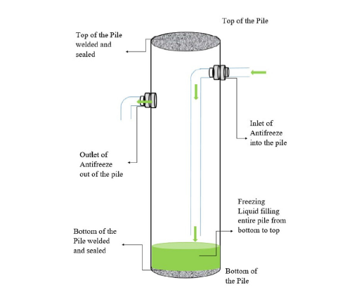
Steel is commonly used for pile construction in cold regions in various configurations such as pipe piles, H-sections, and helical piers. In relatively warm permafrost conditions, open-ended steelpipe and H-steel section piles can be driven to sufficient depths to establish a robust adfreeze bond and provide high bearing capacity. In cold permafrost environments, however, closed-end pipe piles may be installed in oversized predrilled holes and subsequently backfilled with a sand-water slurry. For the purposes of this experiment, steel pipes measuring 1375mm in height and 47mm in diameter were employed for model pile load testing (with an inner diameter of 42mm). The total and average surface roughness values for this specific type of steel were measured using a FARO arm measuring device, yielding values of 9.7μm and 11.3μm, respectively [17]. The model pile was customized to allow for the circulation of antifreeze within the pipe section to investigate the potential reduction in temperature at the pile-soil interface level. Two holes were drilled into the body of the pile to serve as inlet and outlet points for the antifreeze. Utilizing fittings and connecting a lengthy hose inside the pile to the inlet fitting, the antifreeze was pumped into the pile from the bottom until it filled the entire length of the pile up to the top cap. Both the bottom and top of the pile were welded, and all holes, including those for fittings and strain gauge connections, were meticulously sealed to prevent any potential leakage. The outlet was positioned near the top of the pile to ensure proper circulation of the freezing liquid along the length of the pile (Figure 1).
Figure 1:Schematic view of steel pipe with inlet and outlet for circulation of the freezing liquid.
Experimental Setup
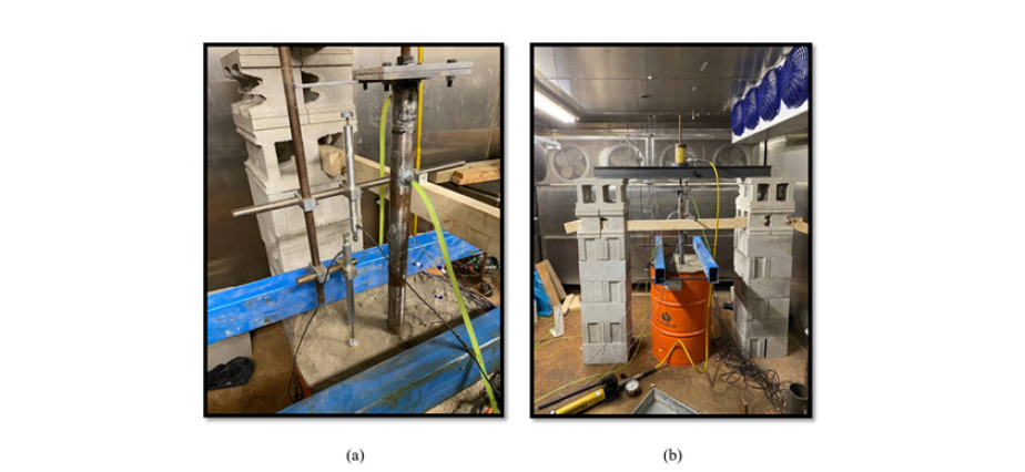
The model pile experimental tests were conducted within the environmental chamber, commonly referred to as the cold room, at Carleton University. This chamber with dimensions of 3m × 4m and a height of 2.4m offers precise temperature control ranging from -20 ˚C to 5 ˚C with an accuracy level of +/- 1 ˚C. To facilitate monotonic loading on model piles, a pile load testing frame was assembled within the environmental chamber. A schematic representation of the test assembly is illustrated in Figure 2. Additionally, a reaction platform was assembled within the environmental chamber to facilitate pull-out load testing. This reaction frame comprised two concrete block columns positioned on either side of the test pile and barrel system. The columns were interconnected via two C Channel-shaped steel reaction beams, with a steel plate positioned across the channel section serving as a reaction platform for the application of axial pull-out loads. Axial pull-out loads were applied using a hydraulic jack coupled to a steel rod connected to the pile head, vertically aligned with the pile axis. Force measurement was conducted using a load cell positioned at the connection point of the steel rod and pile head cap to ensure proper alignment. The load cell was linked to a data logging station for measuring axial resistance, while axial displacement at the pile head and soil surface was recorded by two Linear Variable Differential Transducers (LVDT) devices connected to a reference beam. The reference beam, a 2-inch x 4-inch timber beam, was connected to the reaction columns to accommodate the LVDTs used for monitoring the displacement of the pile during pull-out and soil settlement.
Fgure 2:a) Schematic view of experimental setup, b) A view of the model pile and the soil container (barrel) used in this experiment.
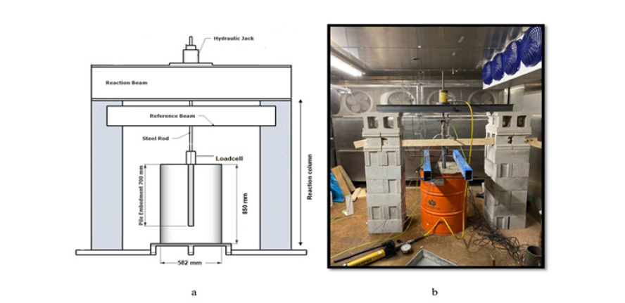
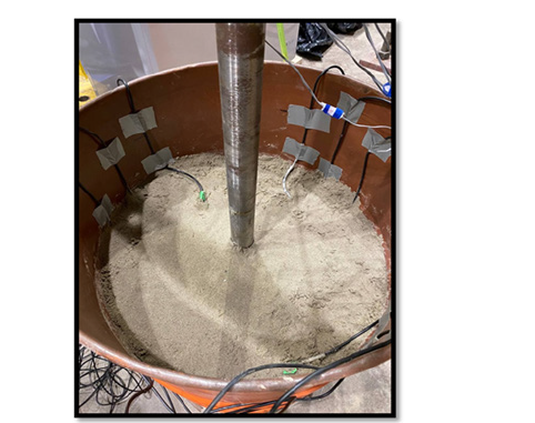
Furthermore, a barrel container measuring 850mm in height and 582mm in diameter was utilized to contain the soil model. The model closed-end pipe pile was embedded within the poorly graded sand in the barrel at an embedment depth of 700mm (Figure 2). In preparation for the model soil, the sand was mixed with approximately 14% moisture content and left within a sealed container for approximately 24 hours to ensure uniform moisture distribution. Subsequently, the soil was layered within the model test container with a thickness of approximately 100mm and compacted to achieve a dry density of approximately 1800kg/m3 (95% of maximum dry density). The uniformity of the sample was maintained by monitoring the thickness of each soil layer. Following the compaction of each soil layer within the barrel, 5TE moisture sensors and thermocouples were strategically placed at various distances from the pile surface within each soil level to monitor moisture content and the temperature of the model soil during testing (Figure 3).
Fgure 3:Model soil preparation and instrumentation.
Instrumentation
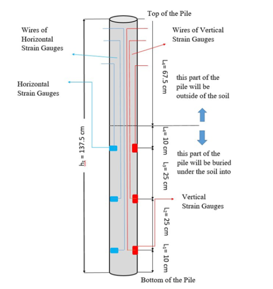
The model pile was outfitted with multiple strain gauges to detect the strain experienced by the pile during the load transfer test (Figure 4). The strain gauges (Tokyo Sokki Kenkyujo Model) were affixed to the exterior of the model pile using M-Bond 200 glue, with the wires routed through a small hole to the interior of the pile. Subsequently, the holes were sealed using multiple applications of M-Coat polyurethane and a protective coat of silicon to waterproof the gauges. Following the attachment of the strain gauges, the input wires were routed through the interior of the pile to the top section, where they were connected to a data acquisition system (NI-MAX). Readings from the strain gauges were obtained both during the circulation of antifreeze into the pile and during pile load testing.
Fgure 4:Strain gauges’ location on model pile.
Fgure 5:a) 5TE sensor layout at each depth, b) Placement of 5TE sensors within the soil.
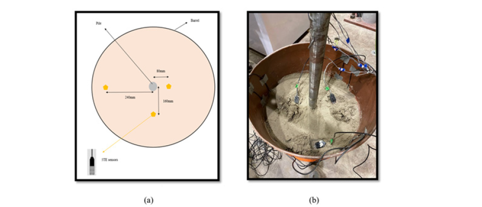
A total of twelve sets of 5TE probes were used to measure the soil’s temperature at various depths and distances from the model pile during testing. These sensors were installed within the soil surrounding the pile at four distinct elevation levels (100mm, 300mm, 500mm, 700mm) and three different distances (10mm, 20mm, 30mm) from the pile to monitor temperature variations in both the vertical and horizontal directions (Figure 5). In addition, a series of thermocouples (Model TT-T-30-SLE-500) were also employed to measure the temperature at the pile-soil interface level and within the soil. These thermocouples are capable of measuring temperatures below the freezing point and were positioned in four sets: one set near the pile surface at depths of 100mm, 300mm, 500mm and 700mm, and the remaining eight sets placed within the soil at intervals between the 5TE sensors and the pile. This placement allowed for the capture of the temperature profile in close proximity to the pile’s surface and facilitated monitoring of temperature variations in both vertical and lateral directions.
LVDTs with an impressive accuracy of 0.01mm were employed to monitor the displacements of both the pile and the soil surface. As illustrated in Figure 6, two LVDTs were incorporated into the experimental setup. One LVDT was installed on the joint plate of the pile to record the displacement of the pile during pile load testing. The other LVDT was positioned on the soil surface near the pile to measure the settlement and potential frost heave of the soil when subjected to freezing temperatures induced by the circulation of antifreeze into the pile.
Fgure 6:a) LVDTs installation locations in experiment setup, b) a view of the whole experimental setup (green tubes used for liquid circulation).
Experimental Procedure
Fgure 7:The freezer and Antifreeze as source of cold temperature.
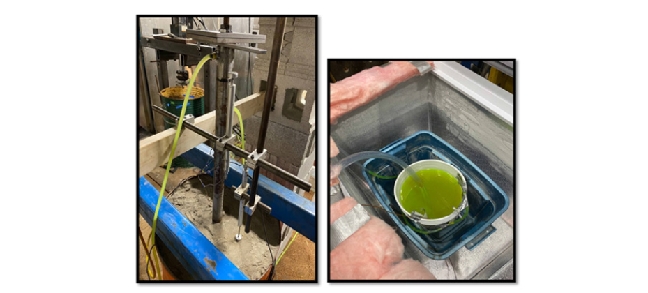
The primary objective of this research was to assess the feasibility of reducing the temperature at the pile-soil interface level. To accomplish this goal, an industrial antifreeze liquid was circulated within the pipe pile to lower the pile’s temperature and induce freezing at the pile-soil interface. A full container of the antifreeze liquid was housed within a freezer set to a temperature of -20 °C, effectively reducing the temperature of the liquid well below its freezing point (Figure 7). Within the environmental chamber, where the pile and soil system were subjected to a temperature of 0 °C to simulate conditions in warming permafrost regions, a 1/12 HP pump was employed to circulate the antifreeze liquid through a 7/16-inch transparent tube from the antifreeze container inside the freezer to the pile’s inlet system. To minimize exposure to ambient air temperature and maintain the desired applied temperature, a layer of insulation was wrapped around the transparent tube. The antifreeze liquid was continuously pumped into the pile through the inlet, which then directed the liquid to the bottom of the pile. Subsequently, after circulating through the pile shaft, the antifreeze liquid was directed back to the freezer via the outlet tube. This circulation process was sustained throughout the duration of the test. To ensure the integrity of the system, all holes and fittings along the pile shaft (including strain gauges, inlet, outlet, bottom, and top cap of the pile) were meticulously sealed through welding and silicon coating.
Pile Load Testing
Axial pull-out load tests were conducted on the model pile both before and after the application of freezing following ASTM D1143/ D1134M (2007) standards [18]. Initially, a pile load test was performed on the model pile while the pile-soil system was exposed to a surface temperature of approximately 0 °C to evaluate the load-carrying capacity of the pile under unfrozen conditions. The loading procedure involved the incremental application of loads at manually controlled intervals, designed to bring the pile to failure while ensuring equilibrium of interface forces. As per the recommendation of De Nicola and Randolph [19], a pile head displacement equivalent to 10% of the pile diameter was considered as the failure criteria to determine the ultimate pile capacity. Subsequent to measuring the initial load transfer of the pile, the antifreeze liquid, exposed to a temperature of -20 °C, was circulated into the model pile over a period of 25 minutes (Figure 7). Once temperature equilibrium was achieved at the pile-soil interface level, a similar pile load test was conducted to evaluate the load-carrying capacity of the model pile under frozen conditions.
Results and Discussion
Pile pull-out bearing capacity without use of cooling system
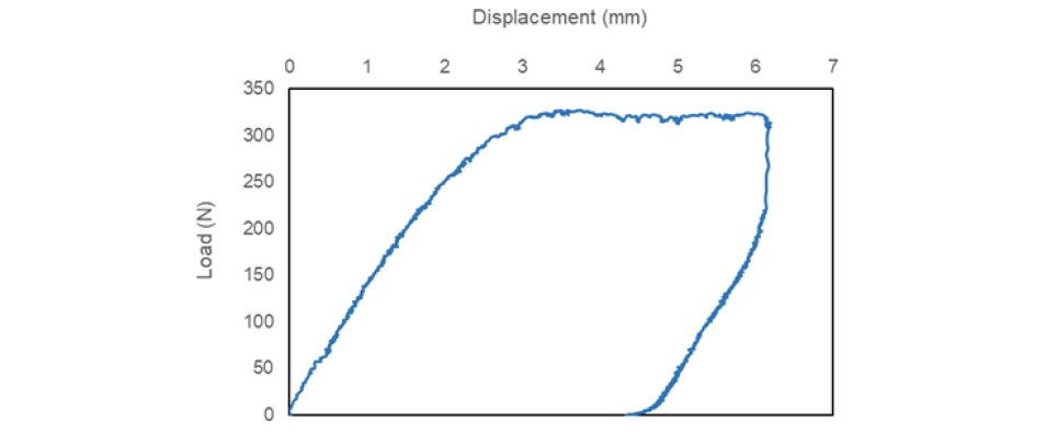
Initially, the pull-out capacity of the pile was assessed under unfrozen conditions, with the soil temperature maintained at around 0 °C. The maximum pull-out capacity of the pile was determined to be 326 N at a pile head displacement of approximately 3mm (Figure 8). It was observed that the pile capacity remained relatively consistent within a range of 3-6mm of pile head displacement, indicating failure at the pile-soil interface. Considering the weight of the pile and the pile cap square plate (approximately 68 N), the actual shaft frictional resistance of the model pile was calculated to be 258 N under unfrozen conditions. This frictional resistance was noted to engage at relatively low displacements, ranging from 3mm to 3.5mm, corresponding to approximately 6-7% of the pile diameter. It is worth noting that this value slightly deviates from the 10% diameter criterion proposed by De Nicola and Randolph [19].
Fgure 8:Pull-out capacity of the model pile in unfrozen condition.
In practice, the pile shaft capacity (Qs) is typically estimated as a function of pile geometry (length and diameter) and the frictional resistance at the soil-pile interface. The shaft resistance (Qs) is often calculated using the equation:
Qs=CLqs (1)
where C is pile circumference, L is pile embedment and qs is the unit shaft resistance (kPa), along the soil-pile contact area. The unit shear strength qs can be defined in terms of the pile-soil interface friction angle (δ), effective stress of the soil (σ’v), and coefficient of lateral earth pressure (Ks). An empirical factor, β, is often used to incorporate the pile-soil interface friction and the coefficient of lateral earth pressure:

For this model pile, the average unit shaft resistance, qs was estimated at approximately 2.35kPa based on the measured pile capacities, calculated by dividing the load transferred to the soil between the pile head and toe by the surface area of the pile. Additionally, the corresponding β-coefficient for the tested pile was estimated to be around 0.33, taking into account the average effective stress around the pile shaft.
Temperature profile of the soil subjected to antifreeze circulation into the pile
Figure 9 illustrates the temperature profiles in soil at distances of 10mm, 20mm, and 30mm from the pile shaft at four distinct soil depths: 100mm, 300mm, 500mm and 700mm from the soil surface. As it is evident in Figure 9, the utilization of freezing liquid within steel pile facilitates the reduction of soil temperature below the freezing point, thereby preserving the frozen state of the soil in warming permafrost regions. The temperature decrease initiated from the soil surface and gradually permeated into deeper soil layers. Notably, the temperature drop was particularly significant at a depth of 100mm from the surface within a remarkably brief period. After only 25 minutes of circulating the freezing liquid through the pile, the temperature at this depth decreased by more than 3 °C. Similarly, within the same timeframe, the soil temperature at a depth of 300mm also dropped to approximately -2.8 °C, significantly lower than the initial soil temperature of about 0 °C. Conversely, the reduction in temperature at deeper soil depths was less pronounced. This discrepancy could be attributed to temperature variations within the cold room, with the upper section of the model container likely experiencing lower temperatures compared to the bottom section. However, further investigation is warranted to thoroughly assess this phenomenon before implementing the technology in practical field applications.
Fgure 9:Soil temperature profile during antifreeze circulation
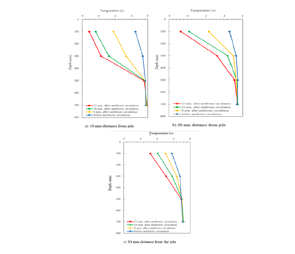
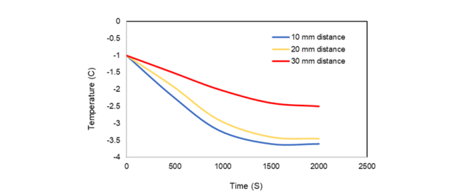
Figure 10 illustrates the temporal evolution of soil temperature over time at three distinct distances, each at a depth of 100mm from the pile. Notably, the soil situated at a proximity of 10mm from the pile exhibited the earliest temperature reduction, occurring approximately 4 minutes into the operation of the freezing system. Within 25 minutes of refrigeration system operation, the soil temperature plummeted to -3.5 ˚C in this area. Subsequently, the soil located at distances of 20mm and 30mm from the pile experienced temperature reductions after 6 minutes and 10 minutes, respectively.
Fgure 10:Variation of soil temperature over time at a depth of 100mm.
These temperature data were gathered using thermocouples, and the “5TE” sensors did not register any changes in temperature when the antifreeze was circulated into the pile. This suggests that the cold liquid circulation employed in this experiment primarily affected the soil immediately surrounding the pile. This limited effect could be attributed to both the finite volume of the antifreeze source (i.e., 10 gallons of -20 ˚C antifreeze liquid) and the restricted exposure time. As the liquid circulated, it absorbed heat from the surrounding soil, gradually warming over time. Although the warmer liquid was returned to the freezer for temperature reduction, the continuous circulation prevented the freezer from significantly lowering and maintaining the antifreeze temperature due to limited exposure time. To freeze a broader area of soil surrounding the pile, a larger volume of antifreeze liquid combined with a larger freezer, facilitating longer exposure times, would be necessary. Moreover, employing an appropriate heat pump could offer a more efficient cooling method compared to the freezer utilized in this study.
Pile pull-out bearing capacity achieved by the use of cooling system
Fgure 11:Pile pull-out testing assembly and setup.
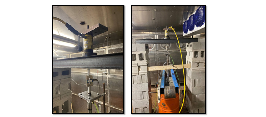
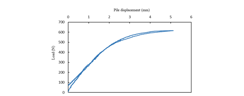
To assess the influence of circulating freezing liquid on the load transfer behavior of the model pile, a pull-out pile load test was conducted while the liquid circulated within the pile (Figure 11). After 25 minutes of liquid circulation, the soil temperature at a distance of 10mm from the pile dropped below the freezing point, ranging from approximately -2.5 ˚C to -3.5 ˚C, up to an embedment depth of about 500mm. Assuming that this temperature change established an adfreeze bond between the pile and the surrounding soil within this depth range, the pull-out load test was initiated 25 minutes after the start of circulation. Similar to the previous load test, the pull-out process was executed using a hydraulic jack and the load cell system. Figure 12 illustrates the load-displacement curve obtained during the load test, revealing a substantial enhancement in the load transfer of the pile due to the partial adfreeze bond formed by the freezing liquid. The maximum pull-out capacity of the model pile was recorded at 616 N, with a pile head displacement of approximately 4-5mm. Considering that this measured value includes the weight of the pile and the pile cap system, deducting their equivalent weight (approximately 68 N) yields an ultimate shaft capacity of 548 N under partially frozen conditions.
Fgure 12:Pile pull-out testing assembly and setup.
The estimation of load transfer in pile foundations within icepoor frozen soil commonly relies on the adfreeze strength of the pile-soil interface, as initially proposed by Weaver and Morgenstern [20]:

where “m” represents an empirical roughness factor that characterizes the pile surface and includes surficial variables such as impurities, while “τlt” denotes the long-term shear strength of frozen soils, typically expressed using the Mohr-Coulomb failure criterion as follows:

where: Clt and flt represent the long-term strength parameters of the frozen soil and σn is the normal stress acting on the pile shaft. Weaver and Morgenstern [20] suggested that the second term in this equation could be disregarded since the normal stress acting on the pile shaft is typically less than 100kPa, rendering the contribution of the frictional component to the total strength insignificant. Therefore, the long-term shear strength of the frozen soil can be simplified to:
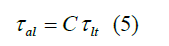
The model pile’s embedment depth within the frozen portion of the soil was approximately 500mm. Considering a proportional shaft capacity of around 74 N for the unfrozen section of the pile (i.e., 200mm) based on the unfrozen pile load test, the shaft capacity within the frozen section of the pile would be approximately 474 N. A roughness factor of 0.7 was deduced for steel piles in ice-poor frozen soils, derived from interface testing conducted by Aldaeef and Rayhani [21]. Assuming the same roughness factor for the model steel pile used in this study, the long-term adfreeze strength for this experiment would be approximately 8.6kPa, more than twice the unit shaft capacity measured in unfrozen condition.
Exposure temperature effect on pile bearing capacity
Comparison between the pile load tests conducted before and after the implementation of the cooling system sheds light on the efficacy of this proposed technology in enhancing the load transfer of the pile. As depicted in Figure 13, the pile shaft capacity exhibited a significant increase from an initial strength of approximately 326 N to about 616 N following exposure to the antifreeze liquid circulation for just 25 minutes. The circulation of the freezing liquid effectively lowered the temperature at the pile-soil interface from around 0 °C to approximately -3 °C, consequently fostering the development of adfreeze strength at this interface and thereby enhancing the pile shaft capacity substantially. Furthermore, analysis of the load-displacement curves for both pile load tests reveals that the loading behavior was predominantly governed by the elastic response of the pile-soil interface under frozen conditions. The elastic nature of the frozen soil induced by the refrigeration system caused the pile to revert to its original position upon unloading. However, a 5mm displacement was sustained in the unfrozen condition test.
Fgure 13:Pull-out capacity of the pile after antifreeze circulation.
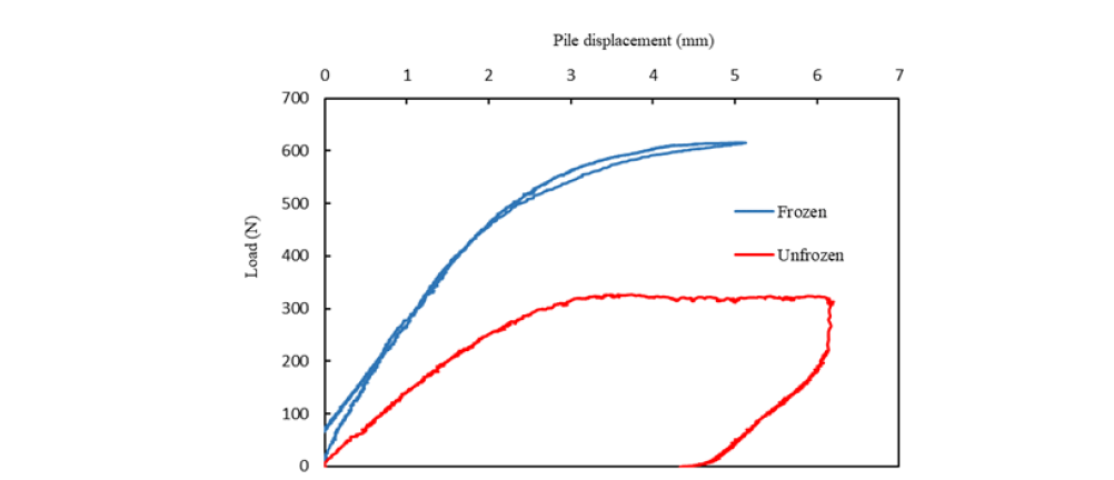
Previous studies, such as the work by Aldaeef and Rayhani [21], have demonstrated that the pull-out capacity of piles in frozen sands can be 4 to 6 times the shaft capacity in thawed soils, depending on the exposure temperature. However, in artificially frozen soil, the shaft capacity observed was only about twice the initial capacity in unfrozen conditions. This limited effect of the proposed cooling system can be attributed partially to the restricted volume of the freezing liquid as well as the small size of the freezer utilized in this study. To maximize freezing potential, a larger volume of liquid and a more extensive freezer system or a heat pump would be necessary.
Conclusion
In this study, a refrigeration technique was investigated with the aim of refreezing thawed soils in permafrost regions to bolster soil bearing capacity and consequently enhance the load carrying capacity of pile foundations. The following conclusions could be drawn from this research.
Within the initial 25 minutes of implementing the refrigeration system, the temperature of the soil surrounding the pile plummeted from approximately 0 ˚C to -3.5 ˚C. This underscores the efficacy of the innovative refrigeration technique developed in this study, demonstrating its ability to lower soil temperature around the pile.
The cooling effect initiated by the freezing system begins at the soil surface and gradually penetrates deeper into the soil layers. This temperature alteration promotes the development of an adfreeze bond between the pile and the adjacent soil, extending to a depth of up to 500mm within the pile’s embedment. Consequently, this partial adfreeze bond has notably enhanced the load transfer capabilities of the pile.
By employing freezing liquid within steel pile foundations, it becomes feasible to lower soil temperature below freezing point, thereby preserving soil in a frozen state, especially crucial in warming permafrost regions. Exposure to the antifreeze liquid circulation resulted in a notable enhancement of the pile shaft capacity, elevating it from an initial strength of approximately 258 N to about 548 N.
The long-term adfreeze strength attained in this experiment was measured at approximately 8.6kPa, exceedingly twice the unit shaft capacity observed in unfrozen conditions. However, the shaft capacity in artificially frozen soil was still less than the shaft capacity in fully frozen ground which could be related to partial freezing achieved in this experiment.
This technology can be applied in pipe pile foundations of existing infrastructure system by implementing a heat pump to control the temperature of the circulating liquid. The limitations of this methodology would include its application to only pipe piles and its need for a source of energy to generale continuous freezing temperature.
Acknowledgments
This study was financially supported by the Natural Sciences and Engineering Research Council of Canada (NSERC). Igor Egorov from National Research Council of Canada (NRC) has provided technical support for the experimental program outlined in this manuscript.
Data Availability
Some or all data, models, or code that support the findings of this study are available from the corresponding author upon reasonable request.
References
- Parameswaran VR (1978) Adfreeze strength of frozen sand to model piles. Canadian Geotechnical Journal 15(4): 494-500.
- Vialov SS, Lunev MV (1988) Experimental investigation of behavior of pile clusters in permafrost soil. Soil Mechanics and Foundation Engineering 25(2): 51-57.
- Vialov SS (1959) Rheological properties and bearing capacity of frozen soils. Translation 74, US. Army CRREL, Hanover.
- Frey KE, McClelland JW (2009) Impacts of permafrost degradation on arctic river biogeochemistry. Hydrological Processes: An International Journal 23(1): 169-182.
- CFEM (2006) Canadian foundation engineering manual. In: (4th edn), Canadian Geotechnical Society, Richmond, British Columbia, Canada.
- Andersland OB, Ladanyi B (2004) Frozen ground engineering. John Wiley & Sons.
- Jellinek HHG (1974) Adhesion of ice frozen from dilute electrolyte solutions. CRREL Research Report 317.
- Qiu K, Yu W, Kong X, Han F, Zhao Y (2024) Investigation on the bearing capacity evolution of building pile foundation during permafrost degradation. Cold Regions Science and Technology 221: 104152.
- Holubec I (2008) Flat loop thermosyphon foundations in warm permafrost. Northwest Territories, Canada. Public Works and Services.
- Popov A, Vaaz S, Usachev A (2010) Review of the current conditions for the application of heat pipes (thermosyphons) to stabilize the temperature of soil bases under facilities in the far North. Heat Pipe Science and Technology 1(1): 89‐98.
- Johnston GH (1981) Permafrost engineering design and construction, Wiley, Toronto, pp. 289–295.
- Sun Z, Liu J, Hu T, You T, Chang D, et al. (2023) Field test study of a novel solar refrigeration pile in permafrost regions. Solar Energy 263: 111845.
- Shang Y, Niu F, Li G, Fang J, Gao Z (2024) Application of a concrete thermal pile in cooling the warming permafrost under climate change. Advances in Climate Change Research 15(1): 170-183.
- Liu W, Chen L, Yu W, Lu Y, Yu F, et al. (2019) Experimental study on thermal performance of quicklime (CaO) energy pile aimed to thaw the warm permafrost ground. Applied Thermal Engineering, 156: 189-195.
- Shang Y, Niu F, Wu X, Liu M (2018) A novel refrigerant system to reduce refreezing time of cast-in-place pile foundation in permafrost regions. Applied Thermal Engineering 128: 1151-1158.
- ASTM D422-63 (2007) Standard test method for particle-size analysis of soils. Annual Book of 484 ASTM Standards, ASTM International, West Conshohocken, PA, USA.
- Giraldo J, Rayhani, MT (2013) Influence of fiber-reinforced polymers on pile–soil interface strength in clays. Advances in Civil Engineering Materials 2(1): 1-17.
- ASTM (2007) Standard test methods for deep foundations under axial compressive load. ASTM International, D1143M-07., West Conshohocken, PA, USA.
- De Nicola A, Randolph MF (1999) Centrifuge modelling of pipe piles in sand under axial loads. Geotechnique 49(3): 295-318.
- Weaver JS, Morgenstern NR (1981) Pile design in permafrost. Canadian Geotechnical Journal 18(3): 357-370.
- Aldaeef AA, Rayhani MT (2019) Interface shear strength characteristics of steel piles in frozen clay under varying exposure temperature. Soils and Foundations 59(6): 2110-2124.
© 2026 Mohammad Rayhani. This is an open access article distributed under the terms of the Creative Commons Attribution License , which permits unrestricted use, distribution, and build upon your work non-commercially.
Editor In Chief






.jpg)





























Signup for Newsletter

Quick Links
 Editorial Board Registrations
 Submit your Article
 Best Paper of the Volume
 Reprints
 Refer a Friend
 Advertise With Us
Our Recent Edition
.jpg)


Top Editors




.jpg)

















.bmp)
.jpg)
.png)
.jpg)













.jpg)






.png)

.png)




.png)




Financial Support

Sponsors

Latest e-Books

Latest Video

 a Creative Commons Attribution 4.0 International License. Based on a work at www.crimsonpublishers.com.
Best viewed in
a Creative Commons Attribution 4.0 International License. Based on a work at www.crimsonpublishers.com.
Best viewed in 
 | Above IE 9.0 version