
- About Us
- Information
-

The Author ensures that the research has been conducted responsibly and ethically with adherence to all relevant regulations. read more..
- For Authors
- For Reviewer
- Manuscript Guidelines
- Membership
- Publication Ethics
-
- Journals
- Reprints
- e-Books
- Videos
- Policies
- Contact Us
 COVID-19
- Submissions


Full Text
Integrative Journal of Conference Proceedings
A Mobile Augmented Reality-Based Approach to Industrial Maintenance Applications
Ozhan Ozkan* and Muhammet Naci Gulsun
Department of Electrical and Electronics Engineering, Faculty of Engineering, Sakarya University, Turkey
*Corresponding author:Ozhan Ozkan, Department of Electrical and Electronics Engineering, Faculty of Engineering, Sakarya University, Turkey
Submission: December 15, 2025;Published: February 05, 2026

Volume4 Issue 3February 05, 2026
Abstract
In today’s highly competitive global manufacturing environments, the continuous and reliable operation of industrial facilities is critically important. Electrical panels, which form the foundation of the production infrastructure by integrating energy distribution, control, and protection functions within a single structure, hold a special significance in maintenance processes. However, maintenance and troubleshooting activities performed on these panels are largely carried out using conventional methods that rely heavily on outdated printed documentation, static labeling, and experience-based approaches. This traditional approach leads to unnecessary time loss during repair and maintenance processes, occupational safety risks resulting from misdiagnosis, and protracted orientation costs for new personnel. This study aims to directly address core issues such as the time loss, high risk of error, and increased cognitive load caused by conventional maintenance procedures. The primary goal is to enhance the efficiency, accuracy, and operational reliability of both planned and unplanned maintenance activities conducted in factory settings. To this end, a mobile device-based maintenance assistant, integrated with Augmented Reality (AR), has been designed and developed. The developed system identifies electrical equipment on the panel in real-time, visually presenting essential technical specifications and instantaneous electrical measurements of the components to the technician. This approach is intended to simplify maintenance processes, shorten the Mean Time to Repair (MTTR), and reduce the margin for operational error. Scenario-based simulations quantify this gain by showing that intermediate information-access steps can be reduced from five to three (~40%); assuming that information search and interpretation account for 40-60% of MTTR, this corresponds to a projected MTTR reduction of approximately 16-24%. In addition, prior AR worker-assistance and AR procedural guidance studies report time savings on the order of ~25% and error-rate reductions reaching ~68.6%, supporting the feasibility of measurable reductions in operational error rate with the proposed approach [1].
Keywords:Augmented reality-assisted maintenance; Hall-effect current sensors; Sensor fusion-based tracking; Mobile maintenance systems; Human-machine interaction
Introduction
The global production and manufacturing sectors are becoming increasingly competitive due to rising market pressures, demands for cost optimization, and high-quality expectations [2]. In this environment, the sustainability of industrial facilities is directly dependent on the reliable and uninterrupted operation of critical infrastructure systems. Electrical panels stand out as central systems in production plants, simultaneously performing functions related to energy distribution, control, and safety [3]. Conversely, industrial maintenance practices are largely conducted within the framework of experience-based knowledge transfer and masterapprentice relationships [4]. Various studies have reported that maintenance activities slow down, the probability of misdiagnosis increases, and occupational safety risks heighten in situations where experienced technicians are not present on-site [5]. This situation makes maintenance processes dependent on individual knowledge, thereby hindering standardization. The printed schematics, labels, and manual checklists utilized in traditional maintenance methods often fail to provide adequate guidance under dynamic field conditions [6]. Particularly in complex panel structures, the inability to rapidly and accurately identify components can lead to prolonged maintenance times and erroneous interventions. Therefore, digitally, interactively, and contextually supporting maintenance processes is considered one of the fundamental requirements of the modern industrial manufacturing paradigm [7].
Materials and Methods
Determining the measurement methodology and halleffect sensors
In industrial electrical panels, voltage levels are mostly fixed by the grid; therefore, current magnitude was selected as the measurement focus in this study [8]. Current is a fundamentally critical parameter in maintenance processes as it directly reflects the operational status of electrical loads, the likelihood of faults, and overall system behavior within the panel. Accordingly, the developed system aimed to enable technicians to access current information quickly and safely in the field. The measurement approach was determined by considering the safety requirements and operational constraints of industrial maintenance environments. Specifically, recognizing the risks posed by direct contact methods when measurements must be taken on energized panels, noncontact measurement techniques were prioritized. In this study, current measurement was given precedence in the electrical panel monitoring application. In the panels examined, the voltage value is largely constant and pre-known, as it is supplied by the main grid. In contrast, the current varies depending on the load status and system operating conditions, providing more direct information about the condition of the components within the panel. For this reason, current measurement was evaluated as a fundamental parameter for system monitoring. While various methods for current measurement exist, Hall-effect sensors were selected as the most suitable solution for the scope of this project. Hall-effect sensors are non-contact sensors based on semiconductor physics that measure current by detecting the magnetic field generated by a current-carrying conductor. The Hall-effect is the phenomenon where a current-carrying wire, when placed at a 90-degree angle to the magnetic field, creates a voltage perpendicular to both the current and the magnetic field. This is visualized in Figure 1.
Figure 1:Magnetic field around a current-carrying wire.

This voltage is called the Hall Voltage (UH). The Lorentz Force (FL) acting on the magnetic field in physical circuits causes this voltage to change. The Lorentz force acting on charge carriers is given by Equation (1):
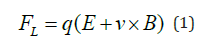
Here, E is the electric field, v is the drift velocity of the charge carrier, B is the magnetic flux density, and q is the elementary charge.
Figure 2 shows a visual representation of this force.
Figure 2:Lorentz Force.

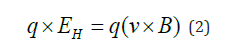
When Hall is activated and reaches a steady state, the magnetic part of the Lorentz force equalizes the resulting Hall electrical force. This electrical equilibrium is given by Equation (2).
Assuming that the magnetic circuit strength is perpendicular to the current, the Hall electrical field equation is given by Equation (3).
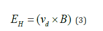
Here, vd is the drift velocity of the charge carriers. This velocity is found using the volumetric current density and the charge carrier density. This can be derived using the magnified Hall voltage. Details of the Hall voltage equation are given by Equation (4).
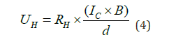
Here, UH is the Hall voltage, RH is the Hall coefficient, IC is the control current through the element, and d is the thickness of the element in meters in the direction of the magnetic field.
Hall-effect sensors are widely used in power electronics and industrial applications [9] because they enable the measurement of both AC and DC currents, offer galvanic isolation, and allow measurements without interrupting the circuit. According to the Hall-effect principle, the magnetic field created around a currentcarrying conductor causes the deflection of charge carriers on the Hall element, resulting in a measurable voltage. This resulting Hall voltage is directly proportional to the magnitude of the magnetic field, and thus the current. In practical applications, the sensors are used together with a core of high magnetic permeability to direct the magnetic flux generated by the conductor onto the Hall element, thereby increasing measurement accuracy [10]. Thanks to the Halleffect sensors used in this study, the currents passing through the components within the panel can be safely measured without interrupting the circuit or disconnecting physical connections. Since sensor outputs are typically low-amplitude analog voltage signals, these signals underwent appropriate signal conditioning stages before being transmitted to the microcontroller. The acquired measurement data were then converted into the digital domain and utilized in system monitoring and evaluation processes.
Signal conditioning and digital data processing
The analog signals obtained from the sensors were appropriately conditioned and digitized to be processed by the microcontroller-based systems. Since the outputs of Hall-effect sensors typically produce low-amplitude analog voltages, these signals were adjusted using operational amplifiers to match the input range of the Analog-to-Digital Converter (ADC). The sampling rate and ADC resolution were determined to ensure accurate representation of the industrial power grid frequency and potential harmonic components [11]. The digitized data was then converted into true current values, taking into account sensor characteristics and calibration coefficients, and subsequently transmitted to the higher-level software layer. This process increased the reliability of the measurement data, establishing a meaningful data source for the Augmented Reality-based visualization. To mitigate measurement noise originating from the Hall-effect sensor frontend and ADC quantization, a lightweight digital filtering stage was integrated prior to visualization. First, an N-point Moving Average (MA) filter was applied to smooth short-term fluctuations and to prevent jitter in the values presented in the AR interface. The MA filter can be defined using Equation (5).
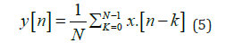
which corresponds to a simple FIR (finite impulse response) low-pass filter with equal coefficients h[k]=1/N for k=0,…,N-1. The choice of N introduces a trade-off between noise attenuation and latency; therefore, N was selected such that the fundamental grid component and relevant low-order harmonics are preserved while high-frequency noise is attenuated. In addition to MA smoothing, a generic FIR low-pass filtering formulation was considered for enhanced suppression of high-frequency disturbances when required. In this case, the filtered signal can be described by Equation (6).
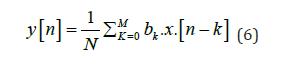
where bk denotes FIR coefficients designed according to the desired cutoff frequency and attenuation characteristics (e.g., window-based designs) under the computational constraints of microcontroller-based processing [12]. From an implementation perspective, the MA filter can be executed efficiently using a running-sum update with O(1) operations per sample, making it suitable for real-time embedded usage, whereas higher-order FIR designs can be applied selectively when additional noise suppression is necessary.
Augmented reality-based visualization and software infrastructure
An Augmented Reality-based visualization approach was adopted to intuitively present the acquired measurement data to the user. The system employs marker-based tracking by detecting a pre-defined reference image of the electrical panel (tracked image/image target) and using the estimated panel pose to anchor the virtual label layer. The application performs real-time pose estimation by leveraging ARCore’s built-in sensor fusion capabilities, which seamlessly combine visual data from the camera with inertial data from the IMU to enhance visual stability [13]. This ensures that virtual content is spatially aligned with the physical panel components, thereby achieving visual stability. The Unity software platform was utilized for the application’s development, leveraging its capabilities for real-time graphics rendering and Augmented Reality (AR) integration [14]. Thanks to Unity’s component-based architecture, the electrical components on the panel were identified with virtual labels; the measured current values and essential technical information were presented to the user through these labels. This approach allowed maintenance personnel to access necessary information instantaneously without interrupting their interaction with the physical panel. The methodological process of the study is described in the sequential steps below.
Design of the AR development environment
The Unity game engine was utilized during the application development process, and the AR Foundation and ARCore XR Plugin packages were integrated to enable AR functionality. These packages facilitated the activation of camera, location, orientation, and image tracking features on Android-based mobile devices. Within the project settings, the Android platform was targeted, OpenGLES 3.0 was exclusively used as the Graphics API, and the compilation backend was configured as IL2CPP. The integrated packages and the settings that were implemented are illustrated in Figures 3-5.
Figure 3:Packages installed in the Unity environment.

Figure 4:Packages installed in the Unity environment.

Figure 5:IL2CPP settings.

Rationale for selecting OpenGLES 3.0 over Vulkan. Although Vulkan can offer lower-level control and potential performance benefits in graphics-intensive workloads, OpenGLES 3.0 was selected in this study to maximize device compatibility and runtime stability across Android-based ARCore-supported smartphones. In practice, Vulkan availability and driver maturity may vary across mobile chipsets and OS versions, which can increase the integration and validation effort for real-time AR applications. Since the proposed system primarily relies on tracked-image detection, pose estimation, and lightweight UI/label rendering, the rendering workload does not require Vulkan-specific features to meet real-time interaction needs. Therefore, OpenGLES 3.0 provides a robust and widely supported baseline that reduces platform fragmentation risks and ensures consistent deployment for the AR Foundation+ARCore pipeline used in this work. Target mobile platform. The application targets Android-based mobile devices that natively support Google ARCore, as AR Foundation relies on the underlying device AR subsystem for camera access, 6DoF motion tracking, and tracked-image detection. In this configuration, OpenGLES 3.0 was selected to ensure broad GPU compatibility and stable real-time rendering on mobile hardware, while IL2CPP was adopted as the compilation backend to comply with modern Android build requirements and to improve runtime stability for AR workloads. Consequently, the proposed implementation assumes an ARCore-supported device class (i.e., 64-bit architecture and ARCore-certified sensor/camera stack), which directly influences achievable frame rate, tracking robustness, and thermal behavior during prolonged operation.
Image-based marker recognition
In this study, the panel alignment is achieved using markerbased image tracking (ARCore Augmented Images/AR Foundation Tracked Images). While ARCore’s internal SLAM capabilities assist in maintaining tracking continuity during movement (hybrid approach), the primary anchoring relies strictly on marker-based recognition to ensure absolute positioning accuracy. In the system, a high-resolution reference image encompassing the front face of the electrical panel was utilized as the marker. This image was added to a Reference Image Library created within Unity, and its physical dimensions were precisely defined. Consequently, when ARCore detects the panel image within the camera feed, it can calculate the spatial position and orientation (pose) of this visual marker. The Reference Image Library configuration is shown in Figure 6.
Figure 6:The Reference Image Library configuration.

Panel tracking mechanism
To enable marker-based detection of the panel visual, an AR Tracked Image Manager component was added to the scene. This component is triggered when the panel image from the reference image library is detected, and the spatial information belonging to the panel visual is obtained. Through a custom-developed tracking script, the position and orientation data of the recognized panel image are acquired, and the virtual layer containing the labels is then positioned according to this information.
Development of the labeling interface
For the purpose of labeling the components on the panel, a Canvas structure operating in World Space mode was created. This structure resides within the same spatial coordinate system as the panel visual and moves synchronously with it. A separate label group was defined for each panel component (e.g., three-phase circuit breaker, single-phase switch, thermal-magnetic circuit breaker). These groups were hierarchically organized to include a background panel and a text component (TextMeshPro). The prefabs for these labels are shown in Figure 7.
Figure 7:Label Prefabs.

Assignment of label locations
To ensure that the labels accurately correspond to the correct components on the panel, each label group was manually positioned on the panel reference image. During this process, the panel visual was used as a reference in the editing phase to determine the relative positions of the labels. At runtime, once the panel visual is detected, all labels are displayed in their correct, predefined locations, fixed relative to the panel.
Mobile application compilation and testing process
The developed application was compiled for the Android platform and extensively tested on mobile devices supporting ARCore. During the tests, it was observed that the application accurately detected the panel visual, the labels were displayed stably on the panel, and positional consistency was maintained despite camera movements.
Simulation Results
Figure 8:General system architecture and data flow diagram of the proposed AR-based maintenance assistant.

Figure 8 illustrates the complete data transmission workflow of the proposed system, extending from the initial data collection phase to its display on the augmented reality interface.
The performance of the proposed non-contact current measurement and AR-based maintenance assistant approach was evaluated through numerical simulations, taking into account the system’s physical components and software workflow. The primary objective of these simulations was to analyze the theoretical accuracy, measurement sensitivity, and potential effects of the developed method on maintenance processes, thereby providing insights into system behavior before real-world field implementations. In this context, the simulations were conducted under three main categories: measurement chain verification, data processing accuracy, and scenario analyses for user interaction.
In the first stage, the Hall-effect sensor-based non-contact current measurement chain was modeled numerically. This model considered the magnetic field generated by the current-carrying conductor, the sensor’s transfer characteristics, and the resulting analog voltage output. The simulations focused on low and medium-level current ranges commonly encountered in industrial panel applications, examining the linear behavior of the sensor output across these ranges. The results demonstrated that the Halleffect sensor output exhibits a linear relationship with the current and that the measurement chain possesses a theoretically stable structure. This finding is consistent with reports in the literature concerning the linear characteristics of Hall-effect sensors in industrial measurement applications.
In the second stage, the process of signal conditioning and digitalization before the sensor output is transmitted to the microcontroller was evaluated. Specifically, the effect of Analogto- Digital Converter (ADC) resolution on measurement accuracy was investigated. Simulations performed for different ADC bit depths revealed that quantization error plays a decisive role in measurement accuracy. It was observed that in ADC configurations with a resolution of 12 bits and above, the error level resulting from quantization remains within acceptable limits for industrial maintenance applications. Conversely, in lower resolutions, it was determined that distinguishing small current changes becomes difficult, and measurement sensitivity decreases. These results indicate that ADC resolution is a critical parameter in system design and that appropriate hardware selection is essential for sound decision-making during maintenance processes. Moreover, applying simple MA/FIR smoothing on the digitized current stream further improves the stability of the displayed measurements by reducing short-term fluctuations caused by sensor noise and quantization effects. Calculations are based on a system reference voltage of 5V. The Hall-effect sensor operates ratiometrically with the supply voltage. By selecting the system’s 5V supply line as the ADC reference voltage, measurement errors caused by potential fluctuations in the power supply are automatically cancelled out. This ratiometric design ensures consistent readings even if the supply voltage varies slightly. On the other hand, since the sensor is powered by a 5V source, its output signal swing covers the 0-5V range. To fully utilize the sensor’s dynamic range without signal clipping or saturation, the ADC reference voltage was set to 5V. Using a lower reference voltage would have restricted the measurable current range. This topic is further detailed in Table 1, which shows the theoretical values of measurement sensitivity based on simulation data for varying resolutions.
Table 1: Theoretical values of measurement precision based on simulation data according to resolution change.

In the third stage, the contribution of the AR component to the maintenance process was analyzed through scenariobased simulations. These analyses compared the conventional maintenance approach with the AR-based maintenance approach in terms of process steps and information access time. The simulation scenarios modeled the steps required for a technician to identify a component on the panel, access the relevant technical information, and interpret the measured values. In the AR-based scenarios, it was observed that presenting this information directly superimposed onto the physical components significantly reduced the intermediate steps required for information access. This effect was assessed as an outcome that reduces the cognitive load of the maintenance process and streamlines the workflow. Furthermore, the impact of the sensor fusion-based positioning approach on visual stability was investigated within the same marker-based tracked-image pipeline. In simulations where the tracked-image pose was stabilized using jointly used camera and IMU data, the spatial alignment of the virtual labels on the panel components was determined to be more stable. Conversely, in scenarios relying on camera-only updates for the tracked-image pose, alignment errors were observed to increase during fast camera movements or in situations with insufficient surface texture. These findings support the importance of the sensor fusion approach in AR systems and validate the limitations associated with tracking methods defined in the literature. The difference between camera-based tracking and camera + IMU tracking is illustrated in Table 2.
Table 2: Illustrating the Effect of IMU.

The simulation-based comparison presented in Table 2 indicates that the combined use of camera and IMU data significantly enhances the spatial alignment stability of virtual labels on the panel components. In scenarios employing only image-based tracking, environmental conditions such as rapid camera movements and insufficient surface texture are shown to increase alignment errors. Moreover, these effects are amplified on mobile devices under constrained conditions such as reduced camera frame rate, thermal throttling, and challenging illumination, which may further increase alignment errors during fast motions. These results underscore the importance of sensor fusion-based positioning approaches in AR systems and support the tracking limitations reported in the literature. Overall, the conducted simulations demonstrate that the proposed system architecture is theoretically consistent and holds the potential to provide significant benefits in industrial maintenance applications. Simulations concerning the measurement chain reveal that the non-contact current measurement approach can operate safely and with adequate sensitivity, while the scenario-based analyses suggest that AR-based information delivery can streamline access to data, thereby potentially reducing process time in maintenance procedures. It must be explicitly emphasized, however, that the results presented in this study are based on numerical simulations, and the performance under real-world field conditions requires validation through future experimental studies.
Conclusion and Discussion
The results obtained indicate that the combination of noncontact current measurement and AR-based visualization significantly reduces the information access time during maintenance processes. The lack of requirement for direct contact with the conductor during measurement offers a critical advantage in terms of occupational safety, particularly in panels operating under power. The stability and repeatability of the Halleffect sensors under industrial panel conditions were found to be consistent with findings reported in previous studies. The AR-based information presentation contributed to technicians identifying components on the panel more quickly and following maintenance steps more systematically. This is particularly important for reducing the cognitive load on inexperienced technicians, aligning with studies that report improvements in user performance in industrial tasks through augmented reality. However, it was observed that marker-based image tracking can be sensitive to environmental factors such as lighting conditions, motion blur, and surface texture; these limitations were deemed parallel to the technical constraints defined in the literature. While the proposed system performs robustly under standard industrial lighting, future iterations aim to enhance tracking stability in low-light conditions or textureless environments. Overall, this study demonstrates that AR technologies can be used in industrial maintenance processes not only as a visual support tool but also as an effective digital tool that guides maintenance activities and supports decisionmaking processes. The findings support the applicability of digital transformation-focused maintenance strategies in industrial facilities and contribute to the maintenance engineering literature.
Conflict of Interest
The authors declare that the research was conducted in the absence of any commercial or financial relationships, which could be construed as a potential conflict of interest.
References
- Palmarini R, Fernández DAI, Ariansyah D, Khan S, Erkoyuncu JA, et al. (2023) Fast augmented reality authoring: Fast creation of AR step-by-step procedures for maintenance operations. IEEE Access 11: 8407-8421.
- Lee J, Bagheri B, Kao HA (2015) A cyber-physical systems architecture for Industry 4.0-based manufacturing systems. Manufacturing Letters 3: 18-23.
- IEC (2018) IEC 60204-1: Safety of machinery-Electrical equipment of machines. International Electrotechnical Commission.
- Collins H (2010) Tacit and explicit knowledge, University of Chicago Press, Chicago, USA.
- Reason J (2000) Human error: Models and management. BMJ 320(7237): 768-770.
- Jardine AKS, Lin D, Banjevic D (2006) A review on machinery diagnostics and prognostics implementing condition-based maintenance. Mechanical Systems and Signal Processing 20(7): 1483-1510.
- Azuma RT (1997) A survey of augmented reality. Presence: Teleoperators and Virtual Environments 6(4): 355-385.
- Hameyer K, Belmans R (1999) Numerical modelling and design of electrical machines and devices. WITPress, Southampton, UK.
- Ripka P (2004) Current sensors using magnetic materials. Journal of Optoelectronics and Advanced Materials 6(2): 587-592.
- Ramsden E (2006) Hall-effect sensors: Theory and application (2nd edn), Elsevier, Amsterdam, Netherlands.
- Oppenheim AV, Schafer RW (2014) Discrete-time signal processing (3rd edn), Pearson, London, UK.
- Harris FJ (1978) On the use of windows for harmonic analysis with the discrete Fourier transform. Proceedings of the IEEE 66(1): 51-83.
- Kim P, Kim J, Song M, Lee Y, Jung M, et al. (2022) A benchmark comparison of four off-the-shelf proprietary visual-inertial odometry systems. Sensors 22(24): 9873.
- Putra BSC, Senapartha IKD, Wang JC, Nendya MB, Pandapotan DD, et al. (2025) Adaptive AR navigation: Real-time mapping for indoor environment using node placement and marker localization. Information 16(6) :478.
© 2026 Ozhan Ozkan. This is an open access article distributed under the terms of the Creative Commons Attribution License , which permits unrestricted use, distribution, and build upon your work non-commercially.
Editor In Chief


.jpg)


Signup for Newsletter

Quick Links
 Editorial Board Registrations
 Submit your Article
 Refer a Friend
 Advertise With Us
Our Recent Edition

.jpg)


Top Editors


.jpg)


.bmp)
.jpg)
.png)
.jpg)


.jpg)


.png)

.png)


.png)


Financial Support

Sponsors

Latest e-Books

Latest Video

 a Creative Commons Attribution 4.0 International License. Based on a work at www.crimsonpublishers.com.
Best viewed in
a Creative Commons Attribution 4.0 International License. Based on a work at www.crimsonpublishers.com.
Best viewed in