

- About Us
- Information
-

The Author ensures that the research has been conducted responsibly and ethically with adherence to all relevant regulations. read more..
- For Authors
- For Reviewer
- Manuscript Guidelines
- Membership
- Publication Ethics
-
- Journals
- Reprints
- e-Books
- Videos
- Policies
- Contact Us
 COVID-19
- Submissions



Full Text
COJ Technical & Scientific Research
Effect of Fibre Orientation and Through- Thickness Composite Micro-Rivets on Interlaminar Shear and Impact Strength of Woven Carbon Fibre Composites
Anto Antony Samy*, Ajin C Sajeevan, Callum Montgomery, David Cole, Rezieh Berah, Lorcan Smith, Calvin Ralph, Alistair McIlhagger, Cormac McGarrigle and Edward Archer*
School of Engineering, Ulster University, UK
*Corresponding author:Ali Kamranpey, Department of Mathematics, University of Guilan, Rasht, Iran
Submission: May 27, 2026:Published: June 16, 2026

Volume6 Issue2June 16, 2026
Abstract
Z-pins/Through-Thickness Composite Micro-Rivets (TTCMR) can improve the out-of-plane properties of laminated composites. This paper presents the results of an experimental investigation into the effect of TTCMR on the out-of-plane interlaminar shear and impact resistance of woven carbon fibre preform laminate composites with different fibre orientation. Both cross-ply [(0,90)4] and quasi-isotropic [(0,90)/ (±45)2/ (0,90)] laminate orientations with TTCMR were fabricated and infused using Vacuum Assisted Resin Transfer Moulding (VARTM). The results indicate that the TTCMR enhances the interlaminar shear and impact strength of woven carbon fibre composites. The failure modes and the presence of crimp/ waviness of the prepared samples before and after short beam strength testing are also investigated by analysis of optical microscopic images. The experimental results showed that riveting has enhanced the out of plane impact strength by 16.45% for cross-ply [(0,90)4] and 50.71% for quasi-isotropic [(0,90)/ (±45)2/ (0,90)] laminates. It also tripled the force bearing capacity. Short beam strength is improved by 1.92% and 11.40% for rivetted cross-ply [(0,90)4] and [(0,90)/(±45)2/(0,90)] laminate samples.
Keywords:Z-pins; Carbon fibre composite; Laminates; VATRM; Mechanical testing
Abbreviations: ILSS: Interlaminar Shear Strength; TTCMR: Through-Thickness Composite Micro-Rivets; RTM: Resin Transfer Moulding; 5HS: 5Harness Satin Weave; μCT: Micro-Computed Tomography; CFRP: Carbon Fibre Reinforced Polymer; VARTM: Vacuum Assisted Resin Transfer Moulding
Introduction
Composites with through-thickness reinforcement have been used for structural applications [1] across various industries, including aircraft manufacturing [2] shipbuilding [3] automotive engineering [4] and heat exchanger systems [5]. Composites with throughthickness reinforcement possess numerous desirable mechanical properties, including high specific strength and stiffness [6] excellent fatigue resistance [7] remarkable anisotropy and design flexibility [8] superior interlaminar shear strength (ILSS) [9] high damage tolerance and resistance and excellent energy absorption during impact loading [10]. They have higher strength to weight ratio and offer better performance as compared to metals and ceramics [11]. The most common types of composite manufacturing methods used in aerospace industry are by laying up of Prepreg, RTM (Resin Transfer Moulding) and Resin Infusion/ Resin Film Infusion [12]. The hand layup of prepreg layers is a significant part of composite manufacturing process, which relies on the expertise and experience of a human workforce to manipulate flat plies into intricate shapes [13]. As an alternative Uddin NS et al. [14] employed the Vacuum Assisted Resin Transfer Moulding (VARTM) process to produce cost-effective Z-pinned junctions for aeronautical structures, investigating aspects such as pin pull-out, load transfer mechanisms under tension and shear pin behaviour. Laminated composite structures are fabricated through the stacking of multiple layers of composite plies, comprising either aligned fibre or fibre fabrics [15]. The orientation of fibres within each ply, as well as their arrangement sequence, plays a pivotal role in determining the functional and structural characteristics of the resultant composite structure [16]. While laminated composites exhibit notable in-plane stiffness and strength, they are susceptible to delamination due to the interface between plies being constituted of matrix material [17] which inherently possesses lower strength compared to fibres. Delamination poses a significant detriment to the compressive performance of laminated composites [18]. Enhanced resistance to delamination can be achieved through the utilization of through-thickness reinforcement [19]. Researchers have proposed multiple techniques for applying through-thickness reinforcement of composite laminates, thereby improving the delamination resistance and ILSS of composite laminates [20]. These include 3D weaving, z-pinning, tufting, knitting, braiding, selective interlayers and hybrid protective layers, or resin toughening [21]. Out of these listed technologies, one of the most reliable and cost-effective techniques is z-pinning. 3D laminate composite with z pins inserted in orthogonal direction have good physical and mechanical properties. Z pinning offers manufacturing repeatability, maximum production rate, superior through-thickness interlaminar fracture toughness, higher through-thickness tensile strain-to-failure values, superior damage resistance, higher impact tolerance, improved damage tolerance, high interlaminar and radial stress resistance due to its complex structure and firm architecture [22-24].
Mouritz AP et al. [25] has reported that z - pins play a major role in through thickness reinforcement since it provides high delamination resistance and excellent joining properties [25,26]. Another work by Mouritz, AP et al. [27] explains the preparation of laminates with different lay-up patterns such as unidirectional, cross-ply, quasi-isotropic and bias orientation. The effect of pinning on the compression modulus and fatigue life of composite laminates was studied and are found to be reduced on increasing concentration of pins. Knaupp M et al. [28] worked on the impact and compression strength of rectangular and circular z-pins on post-impact properties in composite laminates. Laminates showed an improvement of 25% for rectangular and 15% for round pins as compared to that without reinforcement. Knaupp M et al. [29] reported work on influence of pin densities (0.5% and 1%) in fracture toughness by Mode I interlaminar strength. An increase in Mode I properties of 91% and 135% for circular and rectangular z-pins with 0.5% z pin density and an increment of 138 % and 210 % for the circular and rectangular z-pins with 1% z-pin density respectively. The insertion angle of z-pins significantly influences both mode I and mode II failure in composite laminates. Zhang et al. [28] conducted an experimental investigation to explore the impact of different z-pin insertion angles (specifically 60°, 75° and 90°) on the failure modes of cross-ply [(0,90)4] and quasiisotropic [(0,90)/(±45)2/(0,90)] laminates. 90° z-pins were found to be more effective compared to other angled z-pins in enhancing impact damage tolerance. This work aims at development of through-thickness reinforced laminate composites with enhanced out of plane mechanical properties, while aiming to maintain the in-plane performance. It builds on the work by Moses W et al. [29,30] where a novel method of reinforcement (through-thickness composite micro-riveting) is introduced using a polymer/fibre pin as well as conducted extensive experiments to identify the optimum properties for manufacturability and strength performance. Similar in concept to the traditional metal working process of riveting these pins are placed through the thickness with deliberate excess length. The application of heat and pressure deforms the exposed ends of the pin against the part surface. The resultant preform maintains its shape and may be re-formed with further heat and pressure with the reinforcement conforming to the desired shape. Both crossply [(0,90)4] and quasi-isotropic [(0,90)/(±45)2/(0,90)] laminate orientations were fabricated. In this work the TTCMR is placed in orthogonal direction with the help of a bespoke automated machine. The effect of compression during the VARTM process on alignment of rivets composites was observed by analysing the X-ray μCT Scan images of the samples. The impact strength and short beam strength were analysed for finding the out of plane strength of prepared samples. Optical microscopy was employed to investigate the interface between the micro-rivets and the adjacent laminate structure.
Materials and Methods
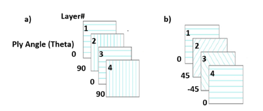
Carbon fibre preforms were manufactured by stacking up layers of 2D woven carbon fibre fabric plies (375g 5-Harness Satin Weave (5HS) 6k Carbon Fibre Cloth-1250mm width; Supplier: Easy composites UK) one over another and stacked together using Aerovac composite one-Aero fix 3 blue spray adhesive. Both crossply [(0,90)4] and quasi-isotropic [(0,90)/(±45)2/(0,90)] laminate orientations were fabricated. Schematic of lay ups are given in Figure 1.
Figure 1:Schematic of composite 5H woven fabric lay ups. a. [(0,90)4] and b. [(0,90)/ (±45)2/ (0,90)].
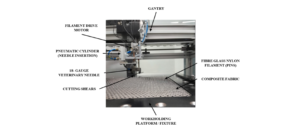
High strength high temperature fibre glass nylon filaments (HSHT-FG; Make: Mark forged, USA) with a diameter of 0.28mm are inserted into the prepared laminates with the help of an automated filament insertion machine developed by Ulster University (manufactured by PAC group, Belfast, UK). Schematic of PAC automated filament insertion machine is shown in Figure 2 and composite laminates undergoing rivet insertion process is shown in Figure 3. The device employed an 18-gauge veterinary needle (SEM inspection revealed an internal diameter of ~860μm, external diameter ~1.4mm) to part the fibres and pass the filament through the preform. The prepared woven carbon fibre preforms are fixed to the detachable work holding platform/fixture with the help of nuts and bolts. Orthogonal pins, composed of yarns or fiberglass nylon filaments, are fed from the yarn storage to the stitching head. This head, equipped with an 18-gauge veterinary needle, inserts the pins into preformed three-dimensional laminates. The 3-axis machine is designed to place rivets at specified intervals and cut the rivets in a desired pattern with predetermined excess length of pin above and below the preform surface with the help of programmable interface. The protective enclosure helps the operator from any sort of exposure from the machine.
Figure 2:Schematic of Ulster University automated micro filament insertion machine.
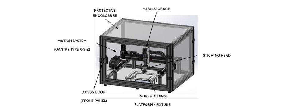
Figure 3:TTCMR sample in the machine.
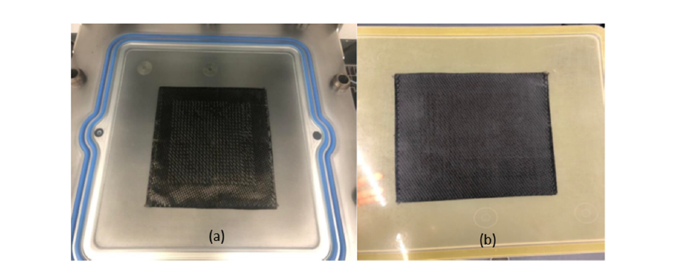
The TTCMR laminates are then placed between two flat upper and lower moulds which close together. The mould is allowed to be placed inside oven for 1 hour at 200 ℃ to melt the nylon thermoplastic in the glass/ nylon filament rivet. This preheating process helps to flatten the inserted rivets allowing better compaction of the laminates as shown in Figure 4. A releasing agent (LOCTITE® FREKOTE 770-NC™) was applied to the clean mould surface, kept at 50 °C in the muffle furnace, in three layers using a piece of blue roll soaked in Frekote liquid at consecutive 15-minute intervals prior to the VARTM process. The resin (Make; Gurit Prime 37) and the hardener (Make: Ampreg 3X slow hardener) are mixed in the ratio of 1000: 290ml and is kept inside a degasifying chamber under vacuum for 15 minutes to remove all the entrapped air bubbles from the mixture. The resin hardener mixture is then injected to an airtight laminate bagging with the help of a resin injection machine (Make: Cijet® One (CIJETI) RTM/VRTM) assisted with a vacuum suction pump (VARTM process). The vacuum bagging scheme is shown in Figure 4. The composite is then allowed to cure overnight at 120 ℃. The cured samples were taken from the mould and mechanical test samples were cut out from the prepared composite using water jet cutting machine (Make: OMAX water jet cutter). Figure 5 shows the VARTM processing of the laminate.
Figure 4:Illustration of preform containing flattened z-pins.
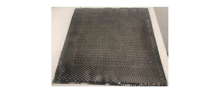
Figure 5:(a) 300mm x 300mm sample placed on top of the mould (b) Finished composite plaque.
The effect of compression during the VARTM process on rivet alignment in composite laminates was investigated using X-ray μCT imaging. Scans were performed with a Bruker Sky Scan 1275 desktop system, which provided detailed visualizations of the structural impact of TTCMR insertion. Another objective is to capture a side-on view of a pin to assess its progression through the composite thickness; however, this proved challenging due to the compound angle at which the pins penetrated the laminate. To address this, a small section measuring 25mm×4mm was extracted and aligned with the predicted pin angle for targeted scanning. Impact strength of the prepared TTCMR laminate composites were measured as per ASTM D 8160-20 with the help of standard testing machines (Made: Avery-Denison). The samples were prepared using a water jet cutting process to dimensions of 1.2mm thickness, 4mm width and 24mm length, in accordance with ASTM standards. Impact Energy is given by,

The beam shear strength of the prepared TTCMR laminate composites were measured as per ASTM D 2344/D2344M-22. The Short-Beam Strength is calculated as follows.
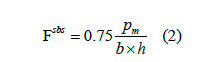
where, Fsbs=short beam strength
Pm=maximum load observed during the test, N
b=measured specimen width, mm
h=measured specimen thickness, mm
The failure modes and the presence of crimp/waviness of the prepared sample before and after short beam strength test are also investigated by taking optical microscopic images with the help of high-resolution microscope (Make: Olympus SZ 40-Zoom stereo microscope 12x magnification), equipped with Am Scope image analysis software.
Results and Discussion
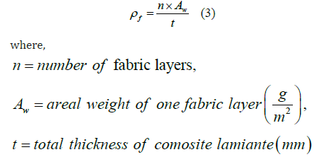
The findings of the investigation and validation of its coherence with the objectives of the research are discussed in this section. The major aim of the present work is to experimentally investigate the effect of TTCMR on the impact strength and ILSS of the carbon fibre composite laminates. Optical microscopic images of the specimens undergone three-point bending under short beam strength test is also analysed to understand the failure modes. The results obtained from impact test and ILSS test is depicted below. In this study the approximate overall fibre volume fraction was found to be 40% for each of the samples produced. This was calculated using the following equation with a given Carbon Fibre density (𝝆f) of 1.76g/ cm3.
X-ray μCT scan
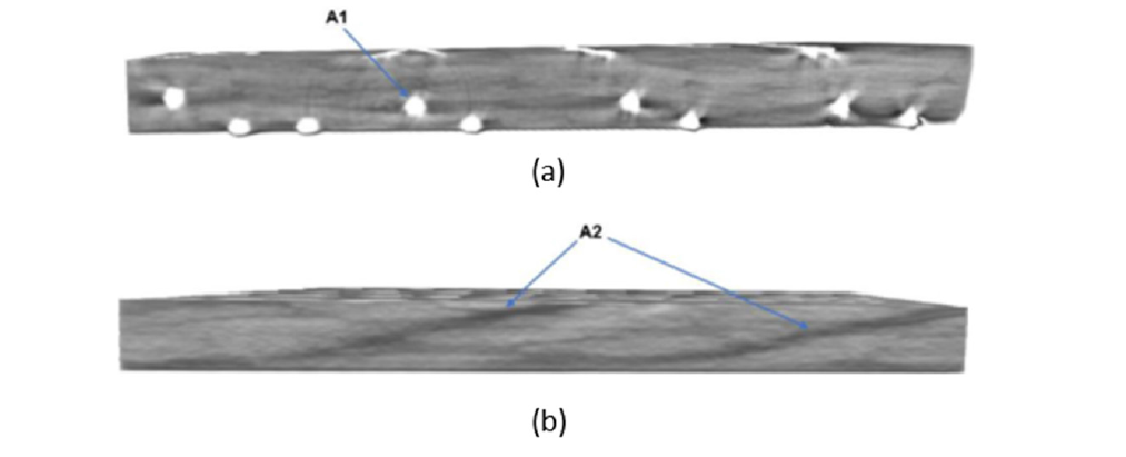
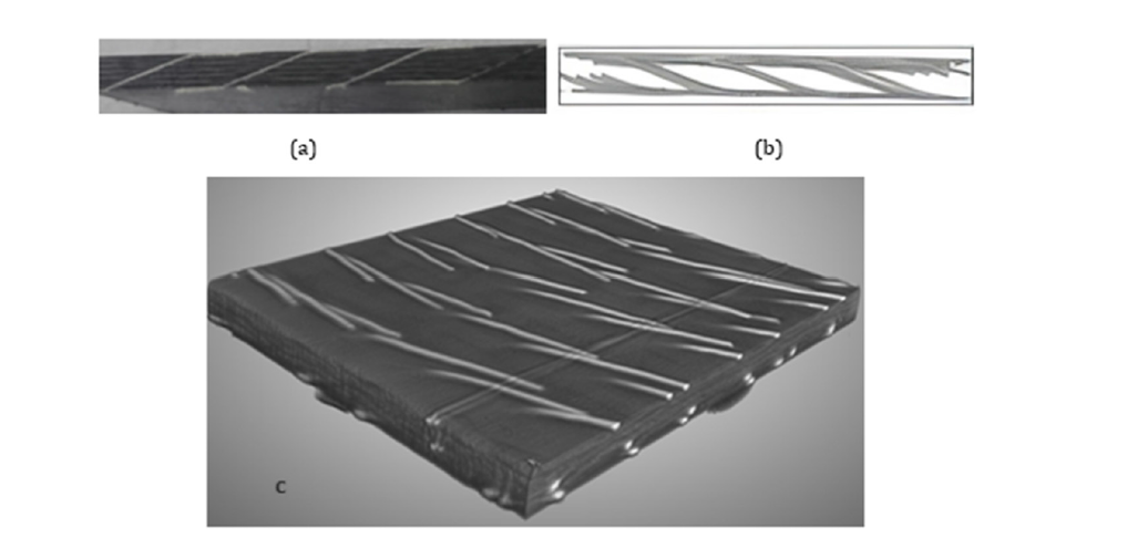
Figure 6 illustrates the side section of a laminate with rivet to investigate its progression through the composite thickness. μCT imaging relies on density differences between phases, but the combination of carbon fibres, hydrocarbon-based resin and polymer pins yields low contrast between components. Despite these limitations, the pins were successfully identified using the grayscale index of the polymer. A 3D rendering confirmed that the pins traverse the laminate at a shallow, compound angle after the compression from the VARTM process. The μCT scan images shown in Figure 6 reveal that rivets tend to shift from an orthogonal orientation as inserted, to approximately 45° during the VRTM process. It was observed that the realignment leads to increased thickness in the quasi-isotropic laminates compared to the cross-ply configuration, offering enhanced reinforcement and reducing the proximity of delamination onset points. Consequently, the likelihood of shear crack propagation and fibre failure is diminished, resulting in improved impact resistance and tensile strength. Figure 7 illustrates the resin rich areas that surround the inserted z-pin. Frequent resin rich zones can combine into a continuous resin channel, that extends along the fibre direction.
Figure 6:The vacuum bagging scheme.
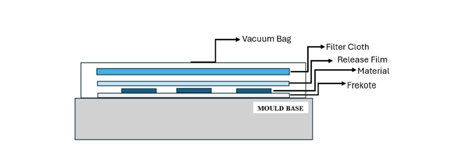
Figure 7:(a) Pin insertion causing fibre distortion (b) Pin insertion creating long chains of resin.
Impact strength
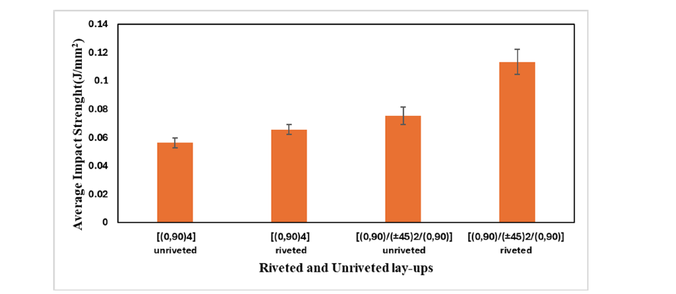
Figure 5 shows the samples after undergoing impact testing. The failure of composite laminate samples undergoing indentation by impact load is attributed by simultaneous matrix/fibres breakage, interlaminar shear and delamination phenomena. During impact loading, the TTCMR fibres stretch under tension, holding the matrix material together for a longer duration. The tensile fibres that have stretched and are now visible on the outer surface are a direct result of this sudden load (b and d). Thus, the TTCMR provides additional reinforcement through the thickness of the laminates, which helps to absorb more load and thereby can improve out of impact strength. Also, the specimens with TTCMR display a blunter failure crack area, with the rivets pulled out of the resin at the surface of the composite which acts like a bridge to improve impact strength. This is indicative of greater energy absorption and deformation of the rivets to dissipate the input energy. The results of Izod impact tests are shown in Figure 8. Figure 8 shows the variation of average impact strength for unriveted and riveted samples. The impact strength is directly proportional to absorbed impact energy and is calculated by dividing absorbed energy by the area of impact. The average absorbed impact energy is observed to increase on the addition of the micro rivets. The best result was observed for quasi-isotropic laminate quasi-isotropic [(0,90)/(±45)2/(0,90)] composite samples with the TTCMR. An increment in out of plane impact strength of 16.45 % and 50.71 % is observed for cross-ply and quasi- isotropic laminates respectively on addition of z pins. A higher impact strength is an indication of better energy absorption, load bearing capacity, damage tolerance and good delamination resistance [1]. The results indicate that the TTCMR has enhanced delamination resistance through improved impact resistance. A higher absorbed impact energy typically correlates with higher impact strength and the material can withstand greater impact forces without failure. As a result, the TTCMR samples display reduced delamination growth compared to non-riveted samples. The magnitude of the delamination area increases proportionally with the increase of impact energy. Also, the TTCMR might reduce the in-plane stiffness due to factors such as fibre waviness and small resin-rich zones as reported my Moses in his earlier work [31]. This could enhance the maximum deflection under impact load, leading to higher interlaminar stresses. Teng et al. reported an improvement of impact load bearing capacity of 23.6% for quasiisotropic [(0,90)/(±45)2/(0,90)] CFRP epoxy laminates with glass fibre z pins than unpinned samples. Similar works by Francesconi disclose results of nearly 50% improvement in impact resistance of z pinned thin [02/ ± 45] carbon/epoxy laminates. Mouritz et al. [25] reported the comparison of out of plane strength of quasiisotropic and cross plied laminates and showed improvement of nearly 14.6% in the impact strength of quasi-isotropic laminates than the balanced laminates both with z pins.
Figure 8:(a) typical optical image of the micro rivets through the composite (b) X-ray μCT Scan image of the micro rivets through the composite with the resin and in-plane fibres removed using grayscale index (c) μCT Scan image of the composite before grayscale index processing.
Short beam shear strength test
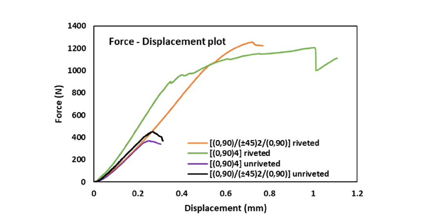
The force displacement diagram for composite laminate samples taken for short beam strength tests are given in Figure 9. The maximum force required for the failure of samples are indicated in the graph. The maximum force achieved for cross-ply [(0,90)4] unriveted, cross-ply [(0,90)4] riveted, quasi-isotropic [(0,90)/ (±45)2/(0,90)] unriveted and quasi-isotropic [(0,90)/(±45)2/ (0,90)] riveted are 370.27N, 1206.69 N, 451.36N and 1255.46N respectively. These results show a nearly threefold increase in maximum force for both the cross-ply [(0/90)4] riveted laminate and quasi-isotropic [(0/90)/(±45)2/(0/90)] riveted laminate, compared to their unriveted counterpart. The short beam strength of is calculated using the Equations 2. The test was conducted on opposite faces of intermediate samples. Figure 10 shows the average short beam strength for the composite laminates. The short beam strength was observed to be increased for riveted samples as compared to unriveted samples. The average short beam results for [(0,90)4] riveted, cross-ply [(0,90)4] unriveted, quasi-isotropic [(0,90)/(±45)2/(0,90)] riveted and quasi-isotropic [(0,90)/(±45)2/(0,90)] unriveted composite laminate are observed to be 27.1MPa, 27.6MPa, 34.5MPa and 38.52MPa respectively. An increment of 1.92% and 11.40 % on short beam strength was observed for cross-ply [(0,90)4] riveted samples and quasiisotropic [(0,90)/(±45)2/(0,90)] riveted sample when compared with their respective unriveted samples. The standard deviation for short beam strength results is observed to be 3.2, 8.35, 3.24 and 8.03 for cross-ply [(0,90)4]riveted, cross-ply [(0,90)4]unriveted, quasi-isotropic [(0,90)/(±45)2/(0,90)] riveted and quasi-isotropic [(0,90)/(±45)2/(0,90)] unriveted composite laminate respectively. The higher standard deviation for riveted samples is due to the presence of a richer resin area on one of the sides of the specimen. Even though the resin rich areas provide better laminate adhesion but at the same time it acts as stress concentrated area which will undergo localized deformation under loading conditions and gives lesser strength value. An improved short beam strength promises a higher stiffness, load bearing capacity and better performance under higher loads. The TTCMR distributes the applied load in a more even manner and helps the material to withstand without breakage for longer period. It also may act as an agent to hold the broken samples from detaching from the parent parts after breaking without harming other moving parts under operation, especially in moving aeroplanes and ship. Mourtiz et al. 2011, 2020 reported an improvement of flexural and short beam shear strength of nearly 23% for quasi-isotropic laminates as compared to balanced one on application of pins. The research also determined that dimensions, angle of insertion and density of pins directly affect the shear failure of laminates. 45-degree orientation was determined to be less susceptible to interlaminar shear under the action of out of plane bending because of its orientation.
Figure 9:a) cross-ply [(0,90)4] unriveted, b) cross-ply [(0,90)4] riveted c) quasi-isotropic [(0,90)/(±45)2/(0,90)] unriveted and d) quasi-isotropic [(0,90)/(±45)2/(0,90)] riveted composite laminates after undergoing impact testing.
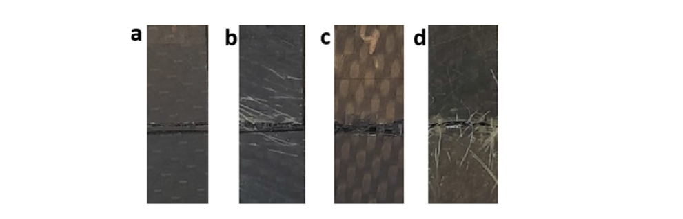
Figure 10:Comparison of average impact strength for riveted and unriveted samples.
Optical microscopy
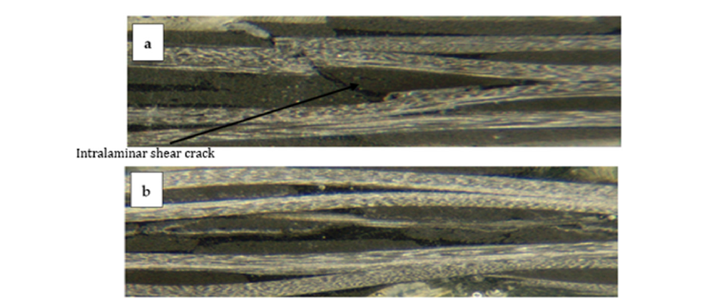
The high resolution optical microscopic images of the riveted and unriveted specimens after bending are shown in Figure 10. Optical images can clarify the failure modes taking place in laminate samples subjected to three-point bending for determining short beam strength. The common failure modes for samples undergone short beam shear is interlaminar shear failure, compressive or tensile flexural damage and inelastic deformation. The failure mechanism involved in the composite laminates were observed with optical microscopic images. It was found that an interlaminar crack could easily be observed in the unriveted specimens, but this was much more difficult to detect in the riveted specimens. Although riveting was generally found to have increased the crimp/ waviness in the in-plane fibre layers the micro-rivets appear to limit cracking. It is postulated that the rivets undergo failure under loading conditions due to factors such as resin compression, fibre fracture and extraction Figure 11.
Figure 11:Average Force - Displacement diagram for a) cross-ply [(0,90)4] unriveted, b) cross-ply [(0,90)4] riveted c) quasi-isotropic [(0,90)/(±45)2/(0,90)] unriveted and d) quasi-isotropic [(0,90)/(±45)2/(0,90)] riveted composite laminates.
Conclusion
The present work experimentally investigated the effect of High strength high temperature fibre glass nylon filaments (HSHT-FG)/ Through-Thickness Composite Micro-Rivets (TTCMR) on the out of plane impact strength and ILSS of carbon preform composite laminates. The failure modes were also observed with the help of high-resolution optical microscope. This is the first published work using the novel bespoke Ulster University automated micro filament insertion machine and it anticipated that further work would follow to develop this method of composite manufacture and to further characterize and model the properties of the manufactured composites. The major observations from the present work are:
A. The out-of-plane impact strength is found to be increased for
TTMCR samples as compared to unriveted samples.
B. An increment in out of plane impact strength of 16.45 %
and 50.71 % is observed for cross-ply and quasi- isotropic
composites respectively after TTMCR.
C. The short beam strength was observed to be increased for
TTMCR samples as compared to unriveted samples. 1.92%
and 11.40 %increment on short beam strength was observed
for cross-ply [(0,90)4] TTMCR samples and quasi-isotropic
[(0,90)/(±45)2/(0,90)] TTMRC samples when compared with
their respective unriveted samples.
D. The optical microscopy images reveal that most of the failures
are due to interlaminar shear in all the samples but interlaminar
cracking is less pronounced in the riveted samples Figure 12 &
13.
Figure 12:Average short beam strength for riveted and unriveted composite laminates.
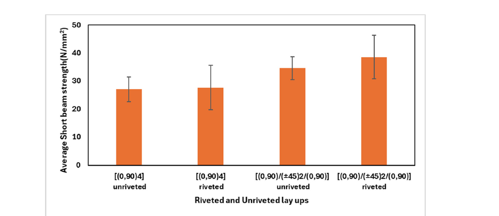
Figure 13:Optical micrographs (1.2x magnification) of a) typical unriveted specimen after bending, b) typical riveted specimen after bending.
Acknowledgement
Anto Antony Samy: Visualisation, Methodology, Writing-review and editing, Ajin C Sajeevan: Writing-original draft, Investigation, Visualisation, Methodology, Formal analysis, Callum Montgomery: Methodology, Formal analysis, Investigation, Writing-original draft, Visualisation, David Cole: Investigation, Visualisation, Methodology, Razieh Berah: Review and editing; Lorcan Smith: review and editing, Cormac McGarrigle: Validation, Resources, Writing-review and editing, Calvin Ralph: Funding acquisition, Supervision, Resources, Alistair McIlhagger: Funding acquisition, Supervision, Resources, Edward Archer: Funding acquisition, Writing-review and editing, Supervision, Conceptualisation, Resources, Project administration.
References
- Mouritz AP, Bannister MK, Falzon PJ, Leong KH (1999) Review of applications for advanced three-dimensional fibre textile composites. Composites Part A: Applied Science and Manufacturing 30(12): 1445-1461.
- Chen Y, Zhang J, Li Z, Zhang H, Chen J, et al. (2023) Manufacturing technology of lightweight fiber-reinforced composite structures in aerospace: Current situation and toward intellectualization. Aerospace 10(3): 206.
- Dolz M, Martinez X, Sá D, Silva J, Jurado A, et al. (2023) Composite materials, technologies and manufacturing: Current scenario of European union shipyards. Ships and Offshore Structures 19(8): 1157-1172.
- Behera BK, Kamble Z (2022) Advanced 3D woven profile structures and their composites for automotive applications. Polymer Composites 43(9): 5946-5953.
- Wang H, Ji R, Qu F, Bai J, Fu Q, et al. (2021) Three-dimensional pore-scale study of the directional heat transfer in a high thermal conductivity carbon/carbon composite protection system. Aerospace Science and Technology 112: 106609.
- Gereke T, Cherif C (2019) A review of numerical models for 3D woven composite reinforcements. Composite Structures 209: 60-66.
- Ma Z, Zhang P, Zhu J (2022) Review on the fatigue properties of 3D woven Fiber/epoxy composites: Testing and modelling strategies. Journal of Industrial Textiles 51(5_suppl): 7755S-7795S.
- Wielhorski Y, Mendoza A, Rubino M, Roux S (2022) Numerical modeling of 3D woven composite reinforcements: A review. Composites Part A: Applied Science and Manufacturing 154: 106729.
- Sun Y, Fan W, Song C, Gao X, Liu T, et al. (2022) Effects of stitch yarns on interlaminar shear behaviour of three-dimensional stitched carbon fibre epoxy composites at room temperature and high temperature. Advanced Composites and Hybrid Materials 5(3): 1951-1965.
- Zhu X, Chen W, Liu L, Xu K, Luo G, et al. (2023) Experimental investigation on high-velocity impact damage and compression after impact behaviour of 2D and 3D textile composites. Composite Structures 303: 116256.
- Clarke J, McIlhagger A, Dixon D, Archer E, Stewart G, et al. (2022) A cost model for 3d woven preforms. Journal of Composites Science 6(1): 18.
- McIlhagger A, Archer E, McIlhagger R (2020) 3-Manufacturing processes for composite materials and components for aerospace applications. Polymer Composites in the Aerospace Industry, pp. 53-75.
- Marouani S, Curtil L, Hamelin P (2008) Composites realized by hand lay-up process in a civil engineering environment: Initial properties and durability. Materials and Structures 41: 831-851.
- Uddin N, Cauthen S, Ramos L, Vaidya UK (2013) Vacuum assisted resin transfer molding (VARTM) for external strengthening of structures. Developments in Fiber-Reinforced Polymer (FRP) Composites for Civil Engineering, pp. 77-114.
- González C, Vilatela JJ, Molina Aldareguía JM, Lopes CS, LLorca J, et al. (2017) Structural composites for multifunctional applications: Current challenges and future trends. Progress in Materials Science 89: 194-251.
- Shah D (2013) Developing plant fibre composites for structural applications by optimising composite parameters: A critical review. Journal of Materials Science 48(18): 6083-6107.
- Wisnom MR (2012) The role of delamination in failure of fibre-reinforced composites. Philosophical Transactions of the Royal Society A: Mathematical, Physical and Engineering Sciences 370(1965): 1850-1870.
- Rhead AT, Butler R, Liu W, Baker N (2012) The influence of surface ply fibre angle on the compressive strength of composite laminates containing delamination. The Aeronautical Journal 116(1186): 1315-1330.
- Gnaba I, Legrand X, Wang P, Soulat D (2019) Through-the-thickness reinforcement for composite structures: A review. Journal of Industrial Textiles 49(1): 71-96.
- Dahale M, Archer E, McIlhagger A, Ralph C, Neale G, et al. (2023) Three-dimensional woven composites. Design and Manufacture of Structural Composites, pp. 189-206.
- Li W, Qiao Y, Fenner J, Warren K, Salviato M, et al. (2021) Elastic and fracture behavior of three-dimensional ply-to-ply angle interlock woven composites: Through-thickness, size effect and multiaxial tests. Composites Part C: Open Access 4: 100098.
- Graham DP, Rezai A, Baker D, Smith PA, Watts JF, et al. (2014) The development and scalability of a high strength, damage tolerant, hybrid joining scheme for composite-metal structures. Composites Part A: Applied Science and Manufacturing 64: 11-24.
- Liu J, Zhang T, Jiang W, Liu J (2019) Mechanical response of a novel composite Y-frame core sandwich panel under shear loading. Composite Structures 224: 111064.
- Mouritz AP (2020) Review of Z-pinned laminates and sandwich composites. Composites Part A: Applied Science and Manufacturing 139: 106128.
- Mouritz AP (2007) Compression properties of Z-pinned composite laminates. Composites Science and Technology 67(15-16): 3110-3120.
- Knaupp M, Baudach F, Franck J, Scharr G, et al. (2013) Impact and post-impact properties of cfrp laminates reinforced with rectangular z-pins. Composites Science and Technology 87: 218-223.
- Knaupp M, Scharr G (2014) Manufacturing process and performance of dry carbon fabrics reinforced with rectangular and circular z-pins. Journal of Composite Materials 48(17): 2163-2172.
- Zhang H, Ding H, Yang D, Xu Q, Ma Y, et al. (2023) Experimental investigation of Z-pin insertion angles on the mechanical behaviour and failure mechanism of compression after impact for CFRP laminates. Composite Structures 304: 116476.
- Moses W, Dooher T, McIlhagger A, Archer E (2022) Polymer/carbon pin through thickness reinforcement. Plastics Rubber and Composites 51(8): 445-453.
- Moses W, Dooher T, Duffy S, McIlhagger A, Archer E (2022) Novel method for interlaminar reinforcement using polymer/fibre pins. Composite Structures 298:
- Francesconi L, Aymerich F (2018) Effect of stitching on the flexure after impact behaviour of thin laminated composites. Proceedings of the Institution of Mechanical Engineers, Part C: Journal of Mechanical Engineering Science 232(8): 1374-1388.
© 2026 Anto Antony Samy and Edward Archer. This is an open access article distributed under the terms of the Creative Commons Attribution License , which permits unrestricted use, distribution, and build upon your work non-commercially.
Editor In Chief







.jpg)































Signup for Newsletter

Quick Links
 Editorial Board Registrations
 Submit your Article
 Best Paper of the Volume
 Reprints
 Refer a Friend
 Advertise With Us
Our Recent Edition

.jpg)



Top Editors




.jpg)

















.bmp)
.jpg)
.png)
.jpg)













.jpg)






.png)

.png)




.png)




Financial Support

Sponsors

Latest e-Books

Latest Video

 a Creative Commons Attribution 4.0 International License. Based on a work at www.crimsonpublishers.com.
Best viewed in
a Creative Commons Attribution 4.0 International License. Based on a work at www.crimsonpublishers.com.
Best viewed in 
 | Above IE 9.0 version