

- About Us
- Information
-

The Author ensures that the research has been conducted responsibly and ethically with adherence to all relevant regulations. read more..
- For Authors
- For Reviewer
- Manuscript Guidelines
- Membership
- Publication Ethics
-
- Journals
- Reprints
- e-Books
- Videos
- Policies
- Contact Us
 COVID-19
- Submissions



Full Text
COJ Robotics & Artificial Intelligence
Optics-Based Depth Estimation of Commercial RGB-D Cameras: A Mini- Review of Intel RealSense D435, D435i, and L515
Jie Zhao*1, Zhengran He2, Stephen Bayne3, Oluwatamilore Dada3 and Wi Ya Lin1
1 Dept. of CS&SE, Penn State University, USA
2 Dept. of EE, Penn State University, USA
3 Dept. of ECE, Texas State University, USA
*Corresponding author: Jie Zhao, Dept. of CS&SE, Penn State University, 5101 Jordan Rd, Erie, PA, 16563, USA
Submission: September 29, 2026;Published: October 27, 2026

ISSN:2832-4463 Volume5 Issue4
Abstract
RGB-D cameras have become important sensing devices for applications requiring simultaneous color
and depth information, including three-dimensional reconstruction, human-computer interaction,
robotics, augmented reality and computer vision. However, commercial RGB-D cameras use different
optical sensing principles, leading to different mechanisms for estimating object depth. This mini-review
examines the optics-based depth estimation principles of three Intel RealSense cameras: the D435, D435i,
and L515. The D435 and D435i use active stereo vision, where depth is determined through epipolar
geometry and triangulation using the disparity between corresponding image points captured by two
infrared cameras. Their depth relationship is  , where D is depth, f is focal length, B is the stereo
baseline, and δ is disparity. Consequently, depth is inversely proportional to disparity. In contrast, L515
uses LiDAR-based time-of-flight sensing, which estimates distance from the propagation characteristics
of emitted and reflected infrared light. For phase-based indirect ToF sensing, depth is calculated from
the measured phase shift and modulation frequency. Numerical examples using camera parameters
demonstrate depth calculations for the stereo and LiDAR approaches. By reviewing these two sensing
mechanisms, this paper provides a concise theoretical foundation for understanding how commercial
RGB-D cameras convert optical measurements into depth information.
Keywords:RGB-D camera; Depth estimation; Intel RealSense; D435; D435i; L515; Stereo vision; LiDAR
Introduction
Depth information adds a spatial dimension beyond conventional two-dimensional RGB imaging and enables a vision system to estimate the distance between a camera and objects in a scene. RGB-D cameras integrate color imaging with depth sensing and have therefore become useful sensing technologies for applications involving three-dimensional scene perception and spatial measurement [1-3]. However, commercial RGB-D cameras do not necessarily estimate depth using the same physical principle. Depending on the sensing architecture, depth can be derived from geometric relationships between multiple images or from the propagation characteristics of emitted light. Understanding these underlying optical principles is important for interpreting depth measurements and selecting appropriate cameras for different computer-vision applications.
The Intel RealSense family provides representative examples of these different approaches. The D435 and D435i use active stereoscopic sensing, with two infrared cameras observing a scene from slightly different viewpoints. Corresponding points in the left and right images produce a disparity that Epipolar geometry and triangulation relate geometrically to object distance. For horizontally aligned cameras, depth depends on focal length, stereo baseline and disparity, with smaller disparity corresponding to greater object distance. The manuscript also specifies a 50-mm baseline for both the D435 and D435i and provides focal-length values for several image resolutions, showing how these physical and imaging parameters enter the depth calculation [4-9].
In contrast, RealSense L515 uses a LiDAR-based time-of-flight approach rather than binocular disparity. In a ToF system, emitted infrared light travels to an object and returns to the sensor, allowing the sensor to infer distance from properties of the returning optical signal. The manuscript describes both direct ToF, which determines distance from round-trip travel time and indirect ToF, which estimates depth from the phase shift between emitted and reflected modulated infrared signals. For phase-based sensing, the measured phase shift and modulation frequency determine the propagation distance for individual pixels, generating a dense depth map [4-9].
Therefore, this mini review focuses on the fundamental optics and mathematical relationships underlying depth estimation in the Intel RealSense D435, D435i, and L515 cameras. This review examines the active-stereo principle through Epipolar geometry, disparity, focal length, and baseline and discusses LiDAR-based ToF depth estimation through light propagation, phase shift, and modulation frequency. Numerical examples also connect these theoretical relationships to the operating parameters of commercial cameras. Through this comparison, the review aims to provide a concise framework for understanding how different RGB-D sensing architectures transform optical information into quantitative depth measurements [4-9].
Sensing Principles and Depth Estimation
Active stereo depth estimation
The D435 and D435i cameras use active stereoscopic sensing. As shown in Figure1 [10], a stereo camera uses two or more lenses spaced apart like human eyes. This arrangement captures two images of the same scene from slightly different perspectives. By mimicking binocular vision, a stereo camera enables depth perception. When the camera or a connected computer compares the two images, it can calculate depth, producing striking Three- Dimensional (3D) effects or accurate spatial measurements (Figure 1).
Figure 1:RealSense D435i camera with left/right IR camera, RGB camera, and IR projector.
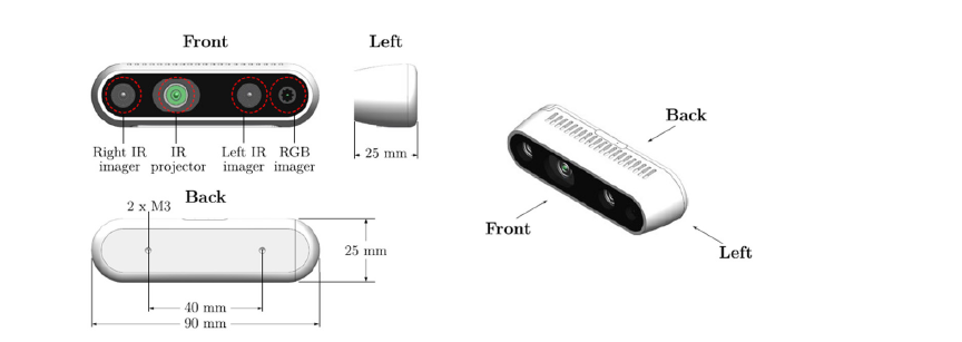
Figure 2:Epipolar geometry.
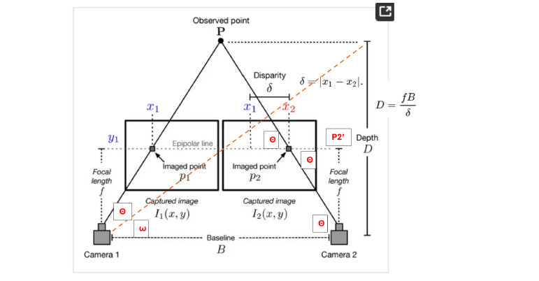
For sensing, the stereo camera uses Epipolar geometry/ triangulation to estimate depth, as shown in (Figure 2) [11].
In Figure 2, because the distances from the observed point P to camera 1 (left camera) and camera 2 (right camera) are equal, they form an isosceles triangle, so the angles θ on both sides are equal. Assuming camera 1 and camera 2 are horizontally aligned and the Epipolar line between points x1 and x2 is also horizontal, the angle θ at P-p2-p1 equals the angle θ at P-Camera2-Camera1.
For depth estimation, two constraints are necessary. Constraint One is that if you extend the Epipolar line from p2 to the focal length at point p2’, the distance between p2 and p2’ is approximately equal to the disparity between x1 and x2. Thus, vertical angles θ are the same. Therefore, the angle θ can be calculated in Equation (1):

In Equation (1), f is the focal length and δ is disparity. Meanwhile, the angle ω is calculated in Equation (2):

In Equation (2), D is the depth, and B is the baseline, the horizontal distance between Camera1 and Camera2.
Constraint Two is that the angle θ between pointers P-Camera1- Camera2 is approximately equal to angle ω, because θ and ω differ only slightly. Based on Constraints One and Two, the depth estimation can be calculated in Equation (3) [12]:
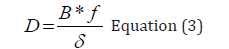
In Equation (3), the inverse relationship means that the smaller the disparity, the greater the depth, and vice versa.
To calculate depth, we need the product data from both depth cameras, D435 and D435i. The focal lengths for both depth cameras, which depend on resolution in pixels, are the same, as shown in (Table 1).
Table 1:The focal lengths at different resolutions for D435 and D435i.

The disparity range is from 0 to 127 pixels, and the Baseline is 50mm for both D435 and D435i. In the example of depth calculation, if the focal length is 643 pixels at a resolution of 1280 X 720 pixels and the disparity is 10.7 pixels, the depth calculation is shown below:

In another example of depth calculation, if the focal length is 426 pixels at a resolution of 848 X 480 pixels and the disparity is 7.1 pixels, the depth calculation is shown below:

Both examples show that the D435 and D435i can have a depth of 3 meters.
LiDAR-based depth estimation
L515 uses a fundamentally different measurement principle. Instead of determining depth primarily from binocular disparity, it uses LiDAR to measure the propagation of infrared laser light. As a Time-of-Flight (ToF) camera, the L515 measures the distance between the camera and the subject for each pixel. It does this by measuring how long artificial light takes to reach the object and return.
There are two types of ToF cameras: Direct and Indirect ToF systems. For a direct ToF system, the camera measures the roundtrip travel time t, as shown in Equation (4) [13]:
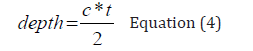
In Equation (4), depth is the distance to the object, c is the speed of light (approximately 3×10⁸m/s), t is the measured round-trip time and 2 means accounts for the light traveling from the camera to the object and back.
The other ToF camera is an indirect camera. Figure 3 shows the sensing principle: a Time-of-Flight (ToF) camera estimates depth by measuring the phase shift of modulated Infrared (IR) light. The camera emits IR light at a known modulation frequency f toward an object and the reflected signal is detected by the camera’s receiver. Because the light travels from the camera to the object and back, the received signal exhibits a phase shift ϕ relative to the emitted signal. The system measures the phase shift for each pixel and converts it into the distance between the camera and the object.
For a phase-based ToF system, the depth is calculated and shown in Equation (5) [13]:

Where d is the object distance, c is the speed of light (approximately 3×10⁸m/s), ∅ is the measured phase shift in radians, and f is the modulation frequency. Thus, a larger phase shift corresponds to a greater propagation distance, within the modulation frequency’s unambiguous measurement range. By performing this calculation independently for every pixel, the ToF camera generates a dense depth map in which each pixel represents the estimated distance from the camera to the corresponding point in the scene (Figure 3).
Figure 3:Depth estimation calculation for ToF camera.
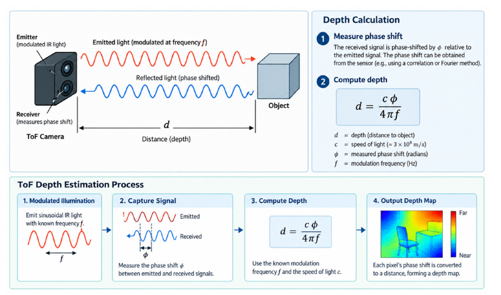
An indirect ToF camera is the RealSense L515, with a maximum modulation frequency of 500MHz and a phase shift range between 0 and 2π radians (0° to 360°). In the example of depth calculation, if the modulation frequency is 15MHz and the phase shift is 324 degrees, the depth calculation is shown below:

The example above shows that the L515 depth can be 9 meters.
Comparison of the D435, D435i, and L515
Although the D435, D435i and L515 all provide synchronized color and depth information, their depth-sensing architectures differ in the physical measurements used to recover object distance. The D435 and D435i estimate depth from stereo disparity, whereas the L515 uses a LiDAR-based time-of-flight measurement. Table 2 summarizes the camera characteristics reported in the accompanying comparison document and highlights the distinctions relevant to optics-based depth estimation (Table 2).
Table 2:Comparison of intel real sense D435, D435i, and L515 cameras [4-9].

Note: IMU denotes an inertial measurement unit, which measures motion-related quantities such as linear acceleration and angular velocity. The operating ranges and other specifications in Table 2 are reproduced from the supplied comparison draft; actual supported modes and usable ranges may depend on device configuration and operating conditions.
Comparison of the active-stereo cameras
The D435 and D435i share the same fundamental active-stereo
depth-estimation principle. As described in Section 2.1, the system
identifies corresponding image points in the left and right infrared
views and converts the measured disparity d to depth via  ,
where f is the focal length and B is the baseline. Consequently, both
cameras share the same geometric relationship: as object distance
increases, disparity decreases, making depth increasingly sensitive
to disparity uncertainty. Their common sensing architecture
suggests broadly similar behavior in static depth measurements
under comparable calibration, resolution, and scene conditions;
however, this does not establish identical measurement accuracy.
The main functional distinction is the D435i’s integrated Inertial Measurement Unit (IMU), which provides motion information in addition to the stereo depth stream. The IMU does not change the triangulation equation or create a new optical depth-estimation method. Instead, inertial measurements can support motion-aware applications, including camera-pose estimation and sensor fusion. Thus, for studies focused on optical depth calculation, the D435 and D435i can be analyzed together, while experiments involving camera movement should account for the D435i’s additional sensing capability.
Comparison of stereo and LiDAR-based depth estimation
The L515 differs more substantially because it obtains depth from the propagation of emitted and reflected infrared light rather than from correspondence between two camera images. As discussed in Section 2.2, the ToF formulation relates distance to the measured optical travel time or phase shift, depending on the measurement method. Unlike stereo vision’s inverse disparity relationship, phase-based ToF depth depends on the phase shift and modulation frequency. Accordingly, stereo correspondence errors are specific to the D435/D435i approach, whereas the L515 is governed by different optical measurement and signal-recovery limitations.
The supplied comparison identifies an approximate operating range of 0.25-9m for the L515, compared with 0.3-3m for the D435 and D435i and a narrower listed depth field of view for the L515. These values illustrate potential differences in coverage and measurement configuration but should not be interpreted as a controlled comparison of accuracy. Although the comparison draft notes that L515 has shown low systematic depth errors in some metrological tests, it does not identify the study or report quantitative results; therefore, it does not claim general superiority in accuracy. Performance comparisons should match distances, target materials, illumination, camera settings and a common ground-truth measurement procedure.
In summary, the D435 and D435i offer closely related stereo triangulation implementations, with the D435i adding inertial sensing, while the L515 offers an alternative LiDAR-based optical measurement principle. This distinction is central when selecting a camera for a specific depth-sensing application or designing a comparative evaluation of depth accuracy and uncertainty.
Conclusion
This mini-review examined the fundamental optics-based depth
estimation principles of three commercial Intel RealSense RGB-D
cameras: the D435, D435i, and L515. Although all three cameras
generate depth information, their underlying measurement
mechanisms differ fundamentally. The D435 and D435i use active
stereo vision, identifying corresponding points in two horizontally
separated infrared images and converting their disparity into
depth through epipolar geometry and triangulation. The resulting
relationship  demonstrates that depth increases as
disparity decreases and that depth estimation is directly influenced
by focal length and stereo baseline. The manuscript’s numerical
examples further show that the D435 and D435i camera parameters
can yield a calculated depth of about 3m.
In contrast, the L515 uses LiDAR-based ToF sensing and therefore does not primarily depend on stereo disparity. It obtains depth from infrared light propagating between the camera and an observed object. Direct ToF determines distance from roundtrip travel time, whereas indirect ToF determines distance from the phase difference between emitted and received modulated signals. The phase-based relationship illustrates how modulation frequency and measured phase shift can be converted into object distance on a pixel-by-pixel basis to generate a dense depth map. The L515 example shows a depth calculation reaching 9m using the selected modulation frequency and phase shift.
Overall, the comparison demonstrates that stereo-based and ToF-based RGB-D cameras obtain the same physical quantity-depththrough distinctly different optical measurements. For the D435 and D435i, disparity is the key observable linking image geometry to depth, whereas for the L515, optical propagation and phase shift form the basis for distance estimation. Understanding these relationships provides a theoretical foundation for interpreting RGB-D depth measurements and for further investigations of depth accuracy, uncertainty, camera configuration, and environmental effects on commercial depth sensors.
References
- Jie Z, Jonnavittulaa R, Ashour O, DiFrancesca D (2025) Measuring student attentiveness using eye-tracking and visual-spatial data analytics. IISE Conference and Expo, USA.
- Jie Z, Ashour O, Mattern M, Norbeck C (2025) 3D facial landmarks video analytics for student engagement. In 2025 6th International Conference on Computers and Artificial Intelligence Technology (CAIT), IEEE, China, pp: 191-197.
- Jie Z, Ashour O (2026) A light-weighted video system with 3D facial landmarks for student engagement. In IISE Annual Conference. Proceedings, USA, pp: 1-6.
- Intel® RealSenseTM Depth Camera D435: Specifications. Intel Corporation, Intel Product Documentation, USA.
- Intel® RealSenseTM Depth Camera D435i: Specifications. Intel Corporation, Intel Product Documentation, USA.
- Intel® RealSenseTM LiDAR Camera L515: Specifications. Intel Corporation, Intel Product Documentation, USA.
- (2024) Best-known-methods for tuning Intel® RealSenseTM D400 depth cameras for best performance. Intel Corporation, Intel RealSense Technical Documentation, USA.
- Intel RealSense D400 Series Datasheet. Intel Corporation, Intel RealSense Technical Documentation, USA.
- (2019) Intel® RealSenseTM depth camera D435i IMU calibration. Intel Corporation, Intel Technical Documentation, USA.
- Federico S, Contenti A, Ulrich L, Marullo G, Moos S, et al. (2025) MOTT modular optical tool tracking framework enabling efficient benchmarking. Scientific Reports 15: 37205.
- Epipolar Geometry
- Jiageng Z, Li M, Liao X, Qing J, Zhang H, et al. (2021) Real-time depth map estimation from infrared stereo images of RGB-D cameras. International Archives of the Photogrammetry, Remote Sensing and Spatial Information Sciences, pp: 107-112.
- Eva C, Araujo H (2022) An experimental assessment of depth estimation in transparent and translucent scenes for intel realsense D415, SR305 and L515. Sensors 22(19): 7378.
© 2026 Jie Zhao. This is an open access article distributed under the terms of the Creative Commons Attribution License , which permits unrestricted use, distribution, and build upon your work non-commercially.
Editor In Chief







.jpg)































Signup for Newsletter

Quick Links
 Editorial Board Registrations
 Submit your Article
 Best Paper of the Volume
 Reprints
 Refer a Friend
 Advertise With Us
Our Recent Edition





Top Editors




.jpg)

















.bmp)
.jpg)
.png)
.jpg)













.jpg)






.png)

.png)




.png)




Financial Support

Sponsors

Latest e-Books

Latest Video

 a Creative Commons Attribution 4.0 International License. Based on a work at www.crimsonpublishers.com.
Best viewed in

 | Above IE 9.0 version