
- About Us
- Information
-

The Author ensures that the research has been conducted responsibly and ethically with adherence to all relevant regulations. read more..
- For Authors
- For Reviewer
- Manuscript Guidelines
- Membership
- Publication Ethics
-
- Journals
- Reprints
- e-Books
- Videos
- Policies
- Contact Us
 COVID-19
- Submissions


Full Text
COJ Robotics & Artificial Intelligence
Reducing the Influence of External Disturbances on the Operation of Quadcopters Using a Neural Regulator
Igor Grishnyaev1* and Vladimir Sleptsov1,2
1Wave Technology Laboratory, Mechanical Engineering Research Institute of the Russian Academy of Sciences, Russia
2MIREA-Russian Technological University, Russia
*Corresponding author: Igor Grishnyaev, Wave Technology Laboratory, Mechanical Engineering Research Institute of the Russian Academy of Sciences, Russia
Submission: March 10, 2026;Published: April 28, 2026

ISSN:2832-4463 Volume5 Issue3
Abstract
Quadcopters (QCs) are used to solve a wide range of problems. However, their operating environment is characterized by high turbulence, which can lead to unintended impacts from external disturbances. The present research aimed to improve quadcopter stability under flight conditions associated with wind loads. To address this, a quadcopter control system using neural networks - a neural regulator - was developed. Mathematical modeling of quadcopter flight, both with and without a neural regulator, was conducted under external influences. Comparison criteria included the completion of transient processes and stabilization of flight altitude. The obtained data demonstrated that the use of a neural regulator in the control system reduces the time it takes to restore a predetermined flight path. This demonstrates the effectiveness of the proposed solution.
Keywords:Quadcopter; Quadcopter control system; Increasing quadcopter flight stability; Using neural networks in quadcopter control
Introduction
Currently, unmanned aerial vehicles in the form of quadcopters are widely used in a wide variety of sectors of the national economy, covering [1-4]:
1. Logistics (delivery of goods and medicines), achieving cost savings of up to 20%;
2. Cadastral work (collecting data on land parcels, compiling cadastral maps), reducing the time to obtain cadastral information by more than a hundredfold.
3. Mineral exploration (obtaining high-precision magnetic field data), reducing exploration costs by up to three times;
4. Forestry and agriculture (creating electronic maps of forests and lands, monitoring agricultural practices), reducing monitoring costs by up to two times and increasing crop yields by 15-20%;
5. Oil and gas sector (infrastructure monitoring, asset inventory), reducing monitoring costs by up to two times and reducing emergency response time by up to three times;
6. Industry (facility monitoring, emergency response), which reduces the time required to monitor complex facilities by up to four times;
7. Law enforcement (road monitoring), which reduces the response time to emergency situations by up to ten times;
8. Border security (territory control), which reduces the time required to monitor complex facilities by up to four times, and so on.
The widespread use of quadcopters is due to their numerous advantages, such as simple and reliable design, low weight with a significant payload mass, compactness and maneuverability, and significantly lower development and manufacturing costs compared to other unmanned aerial vehicles [3,5]. The use of quadcopters in autonomous flight modes is particularly effective [6]. As a rule, quadcopters are characterized by a relatively short flight time (~60min), a small payload (~2kg), a controlled flight distance (~10km), the presence of a GPS/ GLONASS/BDSS positioning module and wireless control carried out by the operator using a portable ground station.
It should be noted that, due to their small weight and dimensions, quadcopters are sensitive to external disturbancesprimarily wind. Therefore, developers and operating organizations devote considerable attention to adapting the quadcopter to these disturbances using various approaches [4,7-10]. One of them is the use of control methods in quadcopters using neural networks to neutralize flight instability caused by the impact of environmental non-stationary and associated wind loads [11-14]. The proposed article presents the results of research on the development and use of a neural controller in the control system of a quadcopter, taking into account its state as a control.
Functional diagram of the quadcopter control system
A distinctive feature of a quadcopter, as an unmanned aerial vehicle, is the presence of four rotors rotating in pairs in opposite directions [6]. The general appearance of a typical quadcopter is shown in (Figure 1).
Figure 1:General view of the quadcopter type Ls-38 GPS RS.

To create a quadcopter control system, we describe its movement in the fixed and moving coordinate systems shown in (Figure 2) [15].
Figure 2:(a) Moving and fixed coordinate systems (b) quadcopter coordinate system.

The following notations are used in the figure: X, Y, Z - fixed coordinate system, X1, Y1, Z1 - moving coordinate system, R - yaw angle; T - pitch angle; K - roll angle.
The differential equations describing the quadcopter dynamics in the presented coordinate systems are as follows [16]:
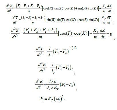
where: Fi-propeller thrust forces (i=1,…,4); Jx, Jy, Jz - moments of inertia of the quadcopter about the corresponding axes; m-quadcopter mass; l-distance from the center of the quadcopter to the attachment points of the electric motors; b-technological coefficient; KT -thrust coefficient; Kx, Ky, Kz-drag forces; ωi - rotation frequency of the i-th propeller.
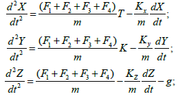
The differential equations (1) presented above can be simplified if we consider the smooth motion of a quadcopter with small roll and pitch angles. In this case, we can assume that cos(K)≈cos(T)≈cos(R)≈1, sin(T)≈T, sin(K)≈K, sin(R)≈0. Then the first three differential equations (1) are reduced to the form:
Based on the circuit with subordinate control of parameters, we will construct a quadcopter control system [17], organizing in it four subsystems for controlling the coordinates X, Y, Z, R with internal control loops for the coordinates T and K. This organization of the control system ensures a combination of a scientific approach with engineering experience. The functional diagram of such a control system will have the form shown in (Figure 3).
Figure 3:Functional diagram of a quadcopter.

In this figure the following notation is used: RPz, RPx, RPy, RPr, RPт, RPк are position controllers for coordinates Z, X, Y, R, T, K, respectively; SPz, SPx, SPy, SPr, SPт, SPк are position sensors for coordinates Z, X, Y, R, T, K, respectively; RSr, RSт, RSк are speed controllers for coordinates R, T, K, respectively; SSr, SSт, SSк are speed sensors for coordinates R, T, K, respectively; ED1,…, ED4 are speed-controlled electric drives; CD1, CD2 are nonlinear correction devices; P is the weight of the quadcopter; Ктz, Ктт, Ктк, Ктr are thrust coefficients for coordinates Z, T, K, R, respectively; Vz, Vт, Vк, Vr are the speed of the quadcopter along the corresponding coordinate; Fz - traction force.
The presented functional diagram is visual and allows for the analysis of the relationship between the control loops of the various quadcopter coordinates. The control loops of the quadcopter coordinates in the diagram shown in Figure 3 are configured for technical and symmetrical optima [18, 19].
A mathematical model of a quadcopter altitude control loop without a neural regulator
Let us consider the process of stabilizing the movement of a quadcopter in space and minimizing the effect of wind on its position using the example of its movement along the Z coordinate (height). The analysis of only one Z coordinate is justified by the fact that the influence of wind disturbances on the quadcopter is greatest in the X-Y plane (due to the largest area in this region).
To do this, from the functional diagram of the quadcopter shown in Figure 3, we will select the subsystem of the control circuit of the control system in the Z coordinate, which ensures its ascent and descent, in the form shown in (Figure 4).
Figure 4:Functional diagram of a Z-coordinate control loop.

In this circuit, the position command signal Urpz along the Z coordinate is algebraically summed with the signal from the position sensor Uspz. The resulting sum is processed in the position controller RPz according to a specific law (for example, proportional-integral). The resulting output signal Ursz sets the rotation speeds V1-V4 of electric drives ED1-ED4 (consisting of electric motors and control systems) and the propellers located on their shafts. This results in a thrust force Fz proportional to the squares of the shaft speeds and the thrust coefficient Ктz. The quadcopter experiences acceleration proportional to the difference between the thrust force Fz, the weight P, and the air resistance force, which depends on the speed Vz. The quadcopter’s speed Vz is determined as the integral of its acceleration, and the position Z is the integral of the speed Vz. Thus, a linear correspondence is established between the position command signal Urpz along the Z coordinate and the quadcopter’s position Z.
To analyze the influence of wind on the behavior of the control loop along the Z coordinate, the authors developed a mathematical model presented in the form of a structural diagram shown in Figure 5. Particularly noteworthy is the structural diagram of a speed-controlled Electric Drive (ED), containing a moment contour [20]. Importantly, this original mathematical model contains nonlinearities (such as asymmetric signal limitation and a quadratic dependence of traction force on electric motor shaft speed), reflecting the key features of quadcopter componentspaired, unidirectional rotation of the electric motor shafts and the laws of aerodynamics. It should be noted that the speed-controlled electric drive used is itself a complex electromechanical system with vector control (Figure 5).
Figure 5:Structural diagram of a Z-coordinate control loop.

In Figure 5 the following notation is used: Prz is the displacement task along the Z coordinate; Wrpz(S) is the transfer function of the position controller along the Z coordinate; S is the Laplace operator; Frp is the nonlinearity of the position controller along the Z coordinate, characterized by the nonlinearity parameters a1, b1; Wrvм(S) is the transfer function of the speed controller of the speed-controlled electric drive; Frv is the nonlinearity of the speed controller of the electric drive, characterized by the nonlinearity parameters a2, b2; Км, Тм are the transmission coefficient and the time constant of the torque loop, respectively; Мм is the electric motor torque; Mr is the load torque; J is the moment of inertia of the electric motor; Kr is the resistance coefficient; Ктz is the traction coefficient; Kvz-coefficient of speed node transfer along the Z coordinate; Pz is the displacement along the Z coordinate.
Results of modeling the quadcopter altitude control loop without a neural regulator
Let us conduct a mathematical modeling of the quadcopter
control loop along the Z coordinate for two cases (without
disturbance and with disturbance) with the following parameters:
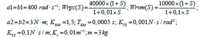
The quadcopter ascends to a height of 10m. The disturbance signal is sent 10 seconds after the start of movement, summing up with the weight P. The results of modeling a quadcopter without external disturbance are shown in (Figure 6).
Figure 6(c) shows that the quadcopter responds to the input (10m ascent) smoothly (without overshoot) within 10 seconds. The results of the quadcopter simulation under external disturbance are shown in (Figure 7).
Figure 6:Transient processes in a quadcopter in the absence of external disturbance: (a) - assignment of movement along the Z coordinate (Prz), (b) - traction force (Fz), (c) - movement along the Z coordinate (Pz).

Figure 7:Transient processes in a quadcopter in the absence of external disturbances: (a) - assignment of movement along the Z coordinate (Prz), (b) - traction force (Fz), (c) - movement along the Z coordinate (Pz).

From Figure 7 (c) it is evident that the quadcopter, as in the previous case, processes the input action (ascent by 10m) smoothly (without overshooting) in 10s, but the external disturbance leads to its descent from 10m to 8m with subsequent restoration of altitude in 9s.
Therefore, the goal is to reduce the impact of external wind forces. Various technical solutions are currently being used to address this issue, including organizing the coordinate control loop in a “sliding mode,” using state observers, applying fuzzy controllers, and so on. According to the authors, a promising approach to solving this problem is the use of a neural regulator.
Mathematical model of a quadcopter altitude control loop with a neural regulator
Let us now consider the possibility of using a neural regulator
in the control loop of a quadcopter along the Z coordinate. Systems
with neural regulator include artificial Neural Networks (NN) and
represent a system of interconnected and interacting elements
called artificial neurons, which are implemented on separate
processors [21,22]. Such NN have a number of advantages:
A. Learning ability;
B. The ability to adapt to changes in the properties of the
controlled object;
C. Resistance to damage to a certain number of neurons.
During the training process, the neural network undergoes a transformation, which involves its parametric optimization. An artificial neuron has a group of synapses (unidirectional input connections) and a single output-an axon. Each synapse is characterized by a weight Li. The synapse weights are determined during neural network training.
The structure of the artificial neuron proposed by McCulloch and Peets is shown in (Figure 8) [23].
Figure 8:Structure of an artificial neuron.

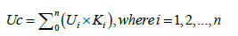
The following notations are used: U1,…,Un - input signals; Uнр - output signal; Uc - intermediate signal; K1,…,Kn - weighting coefficients; F(Uc) - neuron activation function.
The current state of neuron Uc is determined by the weighted sum of its inputs:
The neuron’s output value Uнр is formed as a nonlinear function (activation function) of its state (most often unipolar, sigmoidal, or bipolar). Various types of activation functions are shown in (Figure 9).
Figure 9:Activation functions: (a) - unipolar; (b) - sigmoidal and (c) - bipolar.

The most important issue when designing a neural regulator
is the selection of signals and the determination of weighting
coefficients. In the quadcopter control loop being developed, for the
Z coordinate, we will use:
A. As input signals: position reference Prz, actual position
Pz, speed reference Urvm, and actual speed Vm;
B. As the loop behavior model, a reference model of an
adjustable-speed electric drive with a transfer function Wrm(S);
C. As the output signal, a correction signal Unr, fed to the
position controller.
Taking into account the above, the authors developed a mathematical model of a quadcopter control loop with a two-layer neural regulator along the Z coordinate, the structural diagram of which is presented in (Figure 10).
Figure 10:Structural diagram of the quadcopter control loop along the Z coordinate with a neural regulator.

The following notations are used on it: K1,…,K8 are weight coefficients; Fnr is the sigmoid function.
As can be seen from Figure 10, the neural regulator uses four input signals (plus one from the reference model) and seven weighting coefficients (six in the first layer and two in the second). Finding the weighting coefficients is the primary task of “training” the neural regulator, which can be accomplished using various programs. However, the authors approached this problem using an engineering approach. All input signals were divided into two groups: those related to the motor shaft speed and those related to the control loop position. Since the purpose of the control loop is to minimize the discrepancies between the set parameter values and their actual values, the output signals of each group are the errors in speed and position, respectively. This means that the sums of the coefficients K1, K2, and K3, as well as K5 and K6, must equal zero. Thus, the task of “training” the neural regulator actually comes down to determining only two coefficients-K4 and K7, which is a trivial task. Thus, the combination of scientific and engineering approaches made it possible to synthesize a neural regulator quite simply.
Results of modeling a quadcopter control loop with a neural regulator
Let us conduct a mathematical modeling of the developed quadcopter control loop under the influence of an external disturbance in the form of wind and the following parameters of the neural regulator:
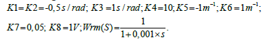
The obtained simulation results are shown in (Figure 11).
Figure 11(c) shows that the quadcopter responds to the input (ascent by 10m) smoothly (without overshoot) in 8s. The external disturbance begins to act 10s after the start of the ascent and causes the quadcopter to descend from 10m to 8.9m. Subsequently, the flight altitude is restored in 6s.
Figure 11:Structural diagram of the quadcopter control loop along the Z coordinate with a neural regulator.

Thus, using a neural regulator with the quadcopter’s control system resulted in a nearly 1.5-fold reduction in altitude recovery time, as demonstrated by comparing the curves presented in Figure 7(c) & Figure 11(c). This demonstrates the effectiveness of the neural controller in reducing the impact of wind loads on its flight.
A prototype of the above-described regulator was developed using the ESP-WROOM-32 module and tested on a DJI Matrice 300 RTK quadcopter. Preliminary testing confirmed the functionality and effectiveness of the neural regulator.
Conclusion
Based on the above, the following conclusions can be drawn:
A. The applications of quadcopters are currently constantly
expanding;
B. The main problem with quadcopters is the dependence
of their flight stability on external disturbances, including wind
loads;
C. Various methods can be used to adapt quadcopters to
external influences, including proportional-integral-differential
controllers, fuzzy controllers, sliding modes, and neural control;
D. A quadcopter control loop with a two-layer neural
regulator for the Z coordinate (flight altitude) has been
developed;
E. Mathematical modeling has shown that the developed
control loop with a neural regulator significantly reduces the
adaptation time of the quadcopter to external influences in the
form of wind loads.
References
- Gritsenko PA, Kremlev AS, Shmigel'skiy GM (2013) Quadcopter motion control according to a preset program. scientific and technical bulletin of information technologies. Mechanics and Optics 48(6): 22-25.
- Epov MI, Zlygostev IN (2012) Application of unmanned aerial vehicles in aerogeophysical reconnaissance. Inter Expo Geo-Siberia 2(3): 22-27.
- Rubin DT, Konev VN, Starikovsky AV, Sheptunov AA, Smirnov AS, et. al (2012) Development of quadcopters with special properties for reconnaissance operations. Special Equipment and Communications 1: 28-30.
- Rokachevsky OA, Sleptsov VV, Ablaeva AE, Phuong DB (2021) Synthesis of the altitude coordinate control loop of the quadcopter information-measuring and control system. Scientific and Technical Bulletin of the Volga Region 1: 38-43.
- Chulin NA, Mironova IV (2018) Unmanned aerial vehicle control system. Engineering Journal: Science and Innovation 9: 1-11.
- Pavlovsky VE, Yatsun SF, Emelyanova OV, Savitsky AV (2014) Modeling and study of quadcopter control processes. Robotics and Technical Cybernetics: Scientific and Technical Journal 4(5): 49-57.
- Yushchenko AS, Lebedev KR, Zabihafar SKh (2017) Quadcopter control system based on an adaptive neural network. Science and Education. Bauman Moscow State Technical University, Russia, 7: 262-267.
- Madani T, Benallegue A (2006) Backstepping control for a quadrotor helicopter. IEEE/RSJ International Conference on Intelligent Robots and Systems, China, pp: 3255-3260.
- Bouadi H, Tadjine M (2007) Nonlinear observer design and sliding mode control of four rotors helicopter. World Academy of Science, Engineering and Technology 25: 225-229.
- Kolotov ME, Smirnova TA (2016) Synthesis of LQR controllers for quadcopter control and their comparative analysis based on simulation modeling using the MATLAB & Simulink software package. Young Scientist 13(115): 172-178.
- Tran VT, Korikov AM (2022) Synthesis of an adaptive sliding mode flight control of a quadcopter under variable load and interference conditions. TUSUR Reports 25(2): 37-44.
- Ogoltsov II, Rozhnin NB, Sheval VV (2015) Development of a mathematical model of spatial flight of a quadcopter. Proceedings of MAI 83: 1-26.
- Zulu A, John S (2014) A review of control algorithms for autonomous quadrotors. Open Journal of Applied Sciences 4: 547-556.
- Kalyagin MYu, Voloshin DA, Mazaev AS (2020) Modeling a quadcopter flight control system in Simulink and Simscape Multibody. Proceedings of MAI 112: 1-27.
- Sleptsov VV, Afonin VL, Ablaeva AE, Phuong DB (2021) Development of a quadcopter information-measuring and control system. Russian Technological Journal 9(6): 26-36.
- Luukkonen T (2011) Modeling and control of quadcopter. School of Science, Espoo, Finland, p. 26.
- Vegera ZhG, Sleptsov VV (2025) Fundamentals of the theory of designing information-measuring and control systems of Copters. Infra-Engineering, Moscow, Russia, p. 128.
- Vegera ZhG, Sleptsov VV (2022) Automated electric drive. MIREA-Russian Technological University, Moscow, Russia, p. 97.
- Terekhov VM (2005) Electric drive control systems. Textbook for students of higher educational institutions. Publishing Center "Academy", Moscow, Russia, p. 304.
- Vegera ZhG, Sleptsov VV (2025) Automated electric drive. Infra-Engineering, Moscow, Vologda, Russia, p. 120.
- Makarov IM, Lokhin VM (2001) Intelligent automatic control systems. FIZMALIT, Moscow, Russia, p. 576.
- Terekhov VA, Efimov DV, Tyukin IYu (2002) Neural network control systems. IPZhR, Moscow, Russia, p. 480.
- Afonin VL, Ilyukhin YuV (2018) Intelligent control in robotics and mechatronics: A study guide. Publishing House of Moscow State Technical University "STANKIN", Moscow, Russia, p. 220.
- Khaikin S (2006) Neural Networks. 2nd (edn), Williams Publishing House, UK, p. 1104.
© 2026 Igor Grishnyaev. This is an open access article distributed under the terms of the Creative Commons Attribution License , which permits unrestricted use, distribution, and build upon your work non-commercially.
Editor In Chief


.jpg)


Signup for Newsletter

Quick Links
 Editorial Board Registrations
 Submit your Article
 Refer a Friend
 Advertise With Us
Our Recent Edition

.jpg)


Top Editors


.jpg)


.bmp)
.jpg)
.png)
.jpg)


.jpg)


.png)

.png)


.png)


Financial Support

Sponsors

Latest e-Books

Latest Video

 a Creative Commons Attribution 4.0 International License. Based on a work at www.crimsonpublishers.com.
Best viewed in
a Creative Commons Attribution 4.0 International License. Based on a work at www.crimsonpublishers.com.
Best viewed in