
- About Us
- Information
-

The Author ensures that the research has been conducted responsibly and ethically with adherence to all relevant regulations. read more..
- For Authors
- For Reviewer
- Manuscript Guidelines
- Membership
- Publication Ethics
-
- Journals
- Reprints
- e-Books
- Videos
- Policies
- Contact Us
 COVID-19
- Submissions


Full Text
Aspects in Mining & Mineral Science
Process Improvements in Electrocoagulation for Production of Healthy Water Free of Arsenic and Lead, Using Air Injection, in La Laguna Area in Mexico
Jose Refugio Parga Torres1*, Gregorio González Zamarripa2, Francisco Cepeda Rodríguez3, Esteban Sánchez Valdés1 and Teresita del Rosario Borrego Jiménez1
1Department of Metallurgy and Materials Science, Mexico
2Metallurgy Faculty, University of Coahuila in Monclova Coahuila, México
3AUC- Faculty of Engineering, Ciudad Universitaria, México
*Corresponding author:Jose Refugio Parga Torres, Department of Metallurgy and Materials Science, Tec NM-ITS in Saltillo, Mexico
Submission: November 12, 2025: Published: December 03, 2025

ISSN 2578-0255Volume14 Issue 3
Abstract
In the last decade in la Laguna Mexico arsenic and lead contaminated natural waters, including surface water and ground water, it is a significant problem as some of these compounds are known as toxic, mutagenic, and carcinogenic. This study has been carried out to determine the feasibility of adsorption of arsenic and lead on iron magnetic species by Electrocoagulation (EC) with air injection process. The full potential of EC with air injection at the bottom of a reactor is presented as an alternative wastewater treatment technique to improve and remove effectively arsenic and lead from well water. Experiments were conducted to determine the optimum operating conditions such as current density, conductivity, pH and retention time in the reactor. In this research study, A.A, FTIR, X-Ray Diffraction and Scanning Electron Microscopy were used to characterize the solid products, which revealed the expected magnetic crystalline iron oxides (lepidocrocite, magnetite, goethite and iron oxide) Results without adding any chemical reagents, based on the laboratory results and using both a prototype and a pilot plant at industrial level. showed that this innovation in the electrocoagulation process with air injection has an efficiency greater than 99% for the removal of arsenic and lead from contaminated effluents from wells water in la Region Lagunera of Mexico.
Keywords:Electrocoagulation; Water purification; Magnetic species; Air injection
Introduction
In Mexico heavy metal contamination exists in aqueous waste streams of many industries, such as extractive metallurgical plants, the printed manufactured industry, coal-fired power plants and industrial operations that involve the processing of ferrous and non-ferrous metals. In 1977, the presence of As in potable water was reported in the city of Torreon, the main city in the Region Lagunera and the site of the most important metallurgic complex of Mexico. Arsenic concentration in Torreon’s water was up 58.1±33.2μg/L and lead Pb was up to 0.302mg per litre (for NOM127-SSA1-1994 (SS 1994) the maximum lead concentration in water is 0.025mg per litre); 52% of the children had As concentrations >50μg/L, and 50.7% of children had Pb≥10μg/dL, far above the present 10-μg/L limit of arsenic in the water [1]. Some metals associated with these activities are Arsenic (As), Lead (Pb), Cadmium (Cd), Chromium (Cr), Gold (Au), Silver (Ag) and Mercury (Hg). Heavy metals are not biodegradable and tend to accumulate in living organisms, causing various diseases and disorders. The metals existing in wastewater are usually removed by precipitation. Other unit operations such as coagulation, flocculation, ion exchange, solvent extraction, cementation, complexation, electrochemical operations, biological operations, adsorption, evaporation, filtration, and membrane process are also used [2]. Such techniques take considerable time and require extensive setup. Each step takes place in a separate tank, and the entire treatment requires several adjustments of pH as well as the addition of acid, coagulant lime or caustic and polymeric flocculants. A very promising electrochemical treatment technique that does not require chemical additions is Electrocoagulation (EC) hermetic reactor. This technology has received very little fundamental attention, although this process has the potential to eliminate the disadvantages of the classical treatment techniques [3].
Specific applications of EC have included defluorination of drinking water [4] and treatment of wastewater streams from: industry wastewater containing heavy metals [5-8], oil containing wastewater [9], foodstuff containing wastewater [10,11], tannery wastewater [12], textile and dyes [13-15], suspended particles [16-18], chemical and mechanical polishing waste [19], organic matter from landfill leachate [20], synthetic detergent effluents [21], metals and phosphate [22], mining-landfill site [23,24] have been reported. The results of applications demonstrate several advantages of EC including high current efficiencies (>90%), short contact times, no pH control required, and much lower operating costs when compared with most of the conventional technologies. Also, the sludge produced by the EC method is often more hydrophobic, which leads to more compact residues. To optimize the removal efficiencies, the water characteristics such as, conductivity, pH and oxidation-reduction potential are adjusted for specific contaminants. Other important characteristics such as particle size, type of electrodes, retention time between plates, plate spacing, and chemical constituent concentrations dictate the operating parameters of the process [22]. Typically, empirical studies are done to determine major EC operating parameters for broad classes of contaminated water or waste streams [23].
The mechanism of EC process operates on the principle that the coagulation is caused by electrolytically produced ions from iron or aluminium anodes, which corrode during electrolysis and cause the release of contaminants from an aqueous medium. The idea in flowing EC techniques is to take advantage of the combined effects of electrolysis gas bubbles (H2) and Green Rust formation, which usually carry the lower density pollutants to the top of the solution where they are concentrated, collected, and removed. These consumable or sacrificial metal electrodes are used to continuously produce the metal ions in the vicinity of the anode. Electrophoretic motion tends to concentrate negatively charged particles in the region of the anode and positively charged ions in the region of the cathode. The released ions at the electrodes neutralize the charge of the particles that are simultaneously forming thereby facilitating coagulation. The metal ions react with the OH- ions produced at the cathode during the evolution of hydrogen, to yield insoluble hydroxides that will adsorb pollutants from the solution and also contribute to coagulation by neutralizing the negatively charged colloidal particles that may be present at neutral or alkaline pHs. This enables the particles to come together under the influence of van der Waals attractive forces.
For wells water treatment with toxic ions metals (As and Pb) in La Region Lagunera in Mexico, this electrochemical phenomenon is ideal, because a reactor for any capacity of effluent treatment plant can be designed. It is an environmentally friendly process since needs low current, and therefore, can be operated by green technology, such as, windmills, gravity, geothermal or solar energy. Also, the magnetic sludge is more readily filterable and can be utilized as a product to make semiconductors/permanent magnets [1]. The EC process needs minimal star up time; the process can be started by turning on the switch.
Background
The elimination of heavy metal species present in contaminated water and aquifers has become an essential requirement in any water treatment scheme, given the toxicity associated with these species and their link to specific health ailments. The need of incorporating simpler and decentralized processes has opened new challenges. It is therefore necessary to optimize purification methods for human consumption, as well as for the cleaning of industrial wastewater effluents before discharging them into other aquatic systems. Typically, empirical studies are done on EC to define major operating parameters for broad classes of contaminated water or waste streams. The EC process operates on the principle that the coagulation is caused by electrolytically produced ions from iron or aluminium anodes, which corrode during electrolysis and cause the release of contaminants from an aqueous medium. Table 1, show this behaviour of the releasing iron and aluminium hydrolysis species to the medium.
Table 1:Iron and aluminium hydrolysis species from electrodes.

These iron or aluminium species from the anodes or sacrificial metal electrodes are used to continuously produce the metal colloids ions in the vicinity of the electrode. Electrophoretic motion tends to concentrate negatively charged particles in the region of the anode and positively charged ions in the region of the cathode. The released ions at the electrodes neutralize the charge of the particles that are simultaneously forming thereby facilitating coagulation. Even inert electrodes, such as titanium and the passage of an alternating current have also been observed to remove metal ions from solution and to initiate the coagulation of suspended solids. An arrangement cell with bipolar electrodes connected in series is shown in Figure 1 & 2. The inner iron electrodes are bipolar, that is they carry both positive and negative charges on opposing faces. These charges develop on the electrode surfaces and are opposite in sign of the charge carried by the parallel electrode surface. During electrolysis the positive side of these bipolar electrodes undergoes anodic reactions, while on the negative side, cathodic reactions occur. The released ions neutralize the charge of the particles and thereby initiate coagulation. The bipolar arrangement reduces the time needed for the treatment due to the increase in surface area mentioned above. This arrangement also has the practical advantage of simplified set-up in that only two monopolar electrodes are connected to the electric power source with no interconnections between the inner bipolar electrodes. To optimize the removal efficiencies the water characteristics such as conductivity that sometimes it is increased, using NaCl, to reduce power consumption, pH and oxidation-reduction potential can be adjusted for specific contaminants. The chemical reactions that have been proposed to describe the setup for the formation of Green Roust in the EC for the production of H2(g), OH- (aq) (cathode) and H+ (aq) and O2(g) (anode) at star the current in the EC cell are:
Figure 1:A schematic diagram of different electrocoagulation systems.

Figure 2:Picture of the experimental setup of the EC reactor cell.

Anode reaction:
Cathode reaction:
Comments:
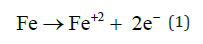
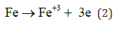
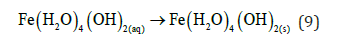
At the Anode reaction:
In EC when current start to flow in the anode the iron corrosion gives the ions that undergoes hydrolysis
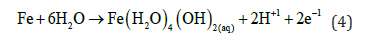
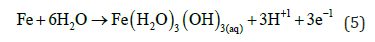
Then the Fe (III) hydroxide begins to precipitate floc with yellowish colour.
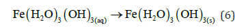
And “Green Rust” may also be formed.
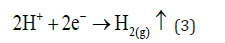
At the Cathode reaction:
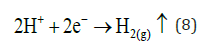
In this electrode side, more hydrogen evolution takes place, but (H+) now comes from weak acids and iron hydrolysis. This reaction mechanism is show in Figure 2-4. Then precipitation of Fe (III) hydroxide (7) continues, and Fe (II) hydroxide precipitation also occurs presenting a dark green floc.
Figure 3:Schematic representation of the hermetic EC cell reactor for removal of toxic ions from water wells [32,33].

Figure 4:View of the top of the particle of the EC process.

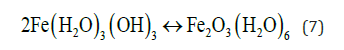
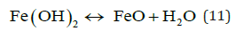
The pH for minimum solubility of Fe (OH)n is in the range of 7-8. EC floc is formed due to the polymerization of iron oxyhydroxides, Table 1. Formation of rust (dehydrated hydroxides) occurs as shown in the following:


Hematite, maghemite, rust, magnetite, lepidocrocite and goethite have been identified as EC by-products by Parga et al. [25,26]. Conditions throughout the cell are not constant concentrations, species of magnetic iron, conductivity and pH are changing. This mechanism may be illustrated with an iron Pourbaix diagram [27]. The process seems to occur in a region parallel to the hydrogen evolution line, and conditions change to the right as highlighted in Figure 5.
Figure 5:Iron Pourbaix Diagram, showing the region and direction in which, the EC process proceeds.

Generally, in the EC process bipolar electrodes are used [28,29]. It has been reported that cells with bipolar electrodes connected in series operating at relatively low current densities produced iron or aluminium coagulant more effectively, more rapidly and more economically when compared to chemical coagulation.
DC vs AC in the EC process
The Direct Current Electrocoagulation (DC) technology is inherent with the formation of an impermeable oxide layer on the cathode as well as deterioration of the anode due to oxidation for the loss of electrons. This leads to the loss of efficiency of the EC unit. These limitations of the DC process have been minimized to some extent by the addition of parallel plate sacrificial electrodes in the cell configuration. However, many have preferred the use of Alternating Current Electrocoagulation (AC) technology [1,25]. It is believed that the AC cyclic energization retards the normal mechanisms of electrode attack that are experienced in DC system, and thus ensure reasonable electrode life. In addition to that, since the AC electric fields in an AC separator do not cause electrophoretic transport of the charged particles due to the frequent change of polarity, it can induce dipole-dipole interactions in a system containing nonspherical charged species. As a result, the AC electric fields may also disrupt the stability of balanced dipolar structures existing in such a system that make more efficient the system.
Electrocoagulation reactor design
The design of the electrochemical reactor is an indispensable step toward achieving maximum Electrocoagulation (EC) efficiency to recover any toxic metal ions. In electrochemical technologies for wastewater treatment, the minimization of the drop between electrodes is especially relevant in order to improve both the electrochemical conversion efficiencies and the energy requirements. The design of EC reactors takes different parameters into account because the effluent and various colloids species affect the hydrodynamic conditions of the reactor during the Electrocoagulation process [30]. The type of EC reactor influences the process performance, but it also affects its operation and scalingup. Per example the EC reactor designed by EPA consists of either a parallel electrode unit in which a series of vertically oriented aluminium electrodes form a series of monopolar electrolytic cells through which the effluent stream passes, or a fluidized bed unit with nonconductive cylinders equipped with no consumable metal electrodes between which a turbulent fluidized bed of aluminium pellets is maintained. Figure 1 shows some of the existing types.
Air distribution at the bottom of the hermetic EC cell
The sparger unit for air distribution, schematically shown in Figure 3, consists of two concentric right-vertical tubes (porous and steel) at the bottom EC cell. The porous inner tube is constructed of any suitable material such as plastic, ceramic, or stainless steel and allows for the sparging of air or any other gas. The outer nonporous tube simply serves to establish a gas jacket and provides for the even distribution of the air through the porous tube. Thus, this distribution device reactor can be used for chemical oxidation in which case increase the corrosion of the iron electrodes and also remove more efficiently the magnetic sludge and the bubbles of air/ hydrogen gas carrying the magnetic species with As and Pb.
The contaminated water is fed at the bottom through the EC cell reactor to develop a swirl flow adjacent to the inside surface of the porous tube, leaving an empty air core centered on the axis of the distribution air unit. The high-velocity swirl flow shears the sparged air to produce a high concentration of small bubbles and intimate interaction between these numerous fine bubbles of air in the cathode sides of the iron electrodes. Sludge of magnetic products that contain As and Pb are then transported to the top of the EC cell faster and efficiently, which result in a significant savings in capital cost.
Experimental Setup and Procedure
The EC electrochemical process system is complex and requires further understanding to improve the efficiency and to extend the concepts to design practice. The EC set up, consisted of a flow-through cell, an electrode assembly, a feed pump and the power supply. A picture of the cell is shown in Figure 2. The EC cell contained twelve parallel carbon steel electrode plates (11.0cmx11.4cm), spaced with 6mm between each cell (electrodes were made of recycled steel, hot rolled but not pickled). The internal volume of the cell is approximately 1200ml, and a variable transformer was used to control the current and potential. A picture of the experimental setup of the EC process is shown in Figure 2. The gas bubbles produced by electrolysis at the cathode iron electrode, carry magnetic iron hydroxides species to the top of the electrolyte, where they are concentrated, to be recovered later, in the filtration step.
Gases rise to the surface, between the iron electrodes, and
present three phenomena:
a. Rapid separation of magnetic iron colloids from the iron
electrodes.
b. Drag destabilized colloids to the surface, forming sludge,
allowing not only a sedimentation extraction, but also, by froth
flotation.
c. Gas bubbles are produced upstream and downstream,
so the flow of the solution leads to a better contact surface,
thereby causing an increase in the efficiency of destabilization.
With iron electrodes, the generation of Fe+3 ions continue with further spontaneous reactions to produce the corresponding poly hydroxides or hydroxides depending on the pH of the aqueous medium see Table 2. The mechanism of electrocoagulation is highly dependent on the chemistry of the aqueous medium, especially conductivity. Other factors such as pH and concentration of chemical reagents also influence the process.
Table 2:Determination of the effect of residence time on removal As.

The electrolyte solutions were prepared with deionized water, with a conductivity of 0.95μS/cm (Aldrich Chemical Co. 99.5+%, A.C.S. reagent, Lot#DI02350AI). Conductivity was raised with 1-gram NaCl per litter (Fisher, 99.8% A.C.S. Certified, lot#995007), and pH was adjusted (as needed) using ~0.13M NaOH solution prepared with NaOH pellets (EM, 97%, lot #36349739). Prior to each trial, the pH and conductivity of each solution was recorded. The solution was pumped through the cell at a flow rate of about 525ml/min and after 2.0 to 4.0 litters of electrolyte solution were treated, the run was stopped, and the slurry pH and conductivity were recorded. Solution and solid were then separated by filtration through cellulose filter paper. A slight oxidation of the samples is expected as the product filtration was carried out without protection from air. The sludge from the electrocoagulation was dried either in an oven or under vacuum at room temperature. In order to find the optimum parameters of the EC process for the removal of arsenic and lead, experiments were carried out by changing, pH of the solution, residence time, voltage and amperage.
Experimental Results and Discussion
The variation of pH during electrolysis is given in Figure 6. The pH of the effluent increases during the electrocoagulation process and levels off at a value approaching pH of 8.5. The increase in pH is due to the formation of hydroxides during hydrogen evolution at the cathode surfaces in the EC apparatus. Optimum operating conditions for the bipolar EC unit were developed from a number of studies and are summarized in Table 3. Removal of more than 99% of arsenic and lead are demonstrated in this research with these conditions. A pictorial and tabular summary of the results of the Electrocoagulation performance test on wells water with arsenic and lead solution. The EC process with air injection has clearly demonstrated that, it is worth noticing that the wastewater probably could have been disposed after the second pass.
Figure 6:Pictures show the effect of the time of the waste-water treatment for formation of green roust (5 minutes), this is the set point for correct operation of the system.

Table 3:Summaries of the 3-step pass in the Industrial EC reactor.

Product characterization
It is difficult to differentiate between the iron oxide and oxyhydroxide species using only a single analytical technique. In this study, Atomic Emission Spectrometry was used for detection of metals ions, sludge trace elements by ICP, Fourier Transform Infrared Spectrometry (FTIR), Powder X-ray Diffraction (XRD), and SEM /EDAX.
Fourier transform infrared spectroscopy
Fourier Transform Infrared Spectra (FTIR) of the solids produced during the EC experiments were obtained. The solids from the EC process were mixed in a 1:20 ratio with KBr, ground to uniformity, and pressed into a pellet. Spectra were collected with an ATI Mattson Genesis Series FTIRTM spectrometer controlled with WinFirstTM software. The FTIR spectrometer was operated within the wavelength region of 4000 to 400 cm-1, with a resolution of either 2 or 4cm-1, and 128 to 512 scans were collected to produce each spectrum. Figure 7 shows the FT-IR spectrum of the byproduct. For details of FT-IR analysis see Table 4. XRD analyses also confirmed the presence of these species detected by FT-IR.
Table 4:FT-IR vibrations and their corresponding wavenumbers and region for the bands observed for the EC-byproduct of iron electrodes.

Figure 7:FT-IR spectrum of iron electrode by-products species.

Ray diffraction
Diffractograms were obtained with a Philips X’Pert MPD system operating with CuKα radiation source filtered with a graphite monochromator (λ=1.5406 Å). The spectrum scan rate was set at 0.02 degrees per sec. For the arsenic magnetic species, a diffractograms was obtained with a Bruker-AXS D4 Endeavor diffractometer operating with CuKα radiation source filtered with a graphite monochromator (λ=1.5406 Å). The samples were ground to a fine powder in isopropyl alcohol (Sigma-Aldrich) and loaded into a sample holder. The XRD scans were recorded from 20 to 70 degrees 2 with 0.020 step-width, and with 10 sec counting time for every step-width. Experiments were run at 40kV and 40mA. Figure 8 shows the diffractogram of arsenic sample obtained from a solution at pH 7 (solution was containing 0.005ppm arsenic). The species identified were magnetite, goethite, lepidocrocite, iron arsenate and iron hydroxide oxide in crystalline form Figure 8.
Figure 8:DRX results of the magnetic species of the sludge.

Scanning electron microscopy (SEM) and energy dispersive analysis of X-rays (EDAX)
The microstructure of the magnetic agglomerate from the sludge of the EC treatment was determined using SEM. Surface morphological analysis was performed through secondary electron imaging and composition analysis using backscattered electron imaging (Figure 4). Finally, based on these outstanding results obtained in this research, the contribution of this study is structured into three principal areas:
A. Environmental problem solution and contaminant valorisation:
This study addresses an environmental challenge, achieving removal of aqueous contaminants, specifically Arsenic (As) and lead (Pb). These pollutants are subsequently valorised through their incorporation into a functional product: magnetic iron species.
B. In situ generation of magnetic iron species:
These magnetic species are generated during the Electrocoagulation (EC) process. The application of an electrical current to a sacrificial iron electrode promotes the formation of compounds such as magnetite (Fe₃O₄), goethite (α-FeOOH), lepidocrocite (γ-FeOOH), and various iron hydroxides.
C. Production of a magnetic precursor for technological applications:
The process yields a magnetic precursor sludge, capable of effectively adsorbing and immobilizing arsenic and lead ions or colloids within its matrix. The resulting material constitutes a valuable product suitable for semiconductor manufacturing.
A Municipal Case Study and Privet EC Pilot Plant
For further examination of the efficacy of this innovation of EC process, as a wells water treatment in La Region Lagunera, to eliminate the toxic elements arsenic and lead, it is worthwhile to examine at least one application [31,32]. The pilot plant with the EC cell reactor was constructed with a non-conductive outer casing and iron electrodes. The electrodes were spaced and alternated (anode/ cathode) to produce a serpentine flow of wastewater and air. The cell was designed for a flow rate of 40 liters/min. Wells water with the toxic ions of arsenic we used during this test had concentrations from 0.02ppm to 0.05ppm. To establish a baseline, 10mts3 of wells water of Region Lagunera, with a mid-range concentration of approximately 0.005ppm was treated. A small amount of bleach was added. Optimal cell operating characteristics were established at 75 amperes and 20 to 50 volts. A small volume of saturated NaCl brine was added to produce adequate solution conductivity. The direction of current flow was reversed automatically performed without operator assistance approximately every 10 minutes to equalize wear on the electrodes and to remove sludge buildup. Figure 9A, show a picture of the pilot plant test on campus of UAT/Wells #50 in Torreon and Figure 9B shows the Mechanism of formation of green roust.
Figure 9:A) Pilot plant (40 liters/minute) in wells # 50 in UAT Torreon and B) Mechanism of formation of green roust simples.

Characteristic of the rectifier used in this industrial pilot plant (40-80 liters/minutes)
Rectifier: Aldonex
DC Output: 5000 Amperes 0-50 Volts
AC Input: 480 Volts 3 Phase 60Hz
Control: SCR with Constant Current and Constant Voltage
with Automatic Polarity Reverse.
Cooling: Air
KW: 250 Max
A.C. Draw: 440 @ Max KW
Cabinet: 70 Hx50 Wx50 D Powder Coat Steel
Remote: Fiberglass/Polyester 10”x12” x 5.5”
Ripple: 5% Ripple at Full Output. Additional Filtering available
Ramping: Soft Start is Standard
Protection: Automatic Phase Sequence Indicator with Voltage and Phase Loss Cut-off. Automatic Current Trip. Thermal Shutdowns
Metering: Analog DC Ammeter & Voltmeter with Lifetime Hour Meter in Remote.
EC Cell Reactor: 200 liters Filter: 1 unit Thicker Gravity sedimentation: 1 unit Storage Clean Water Tank: 40mts3 ( Operation 10 hours/day)
The Figure 10 shows the EC pilot plant from the private company Hidrosoluciones in Mexico y Elequa with capacity of 1 cubic meter per day. This plant was proved with the use of solar energy.
Figure 10:Total system of the pilot plant from Hidrosoluciones en Mexico y Elequa.

Operation costs of electrocoagulation technology
A great advantage of the electrocoagulation technology is that the capital and operating costs scale with the size of the electrocoagulation unit and the amount of hazardous waste to be treated. Units are available that range from bench size costing only a few thousand dollars to large units capable of treating hundreds of cubic meters per minute for hundreds of thousands of dollars. Treatment costs can be as small as $0.10 per mt3. All this depends on the amount of the wastewater treatment removal required. Finally, the results of this research work were shared with CONAGUA (Programa Federal Agua Saludable Region Lagunera) and Comite Ciudadano de la Laguna en Defensa de la Calidad de Agua y ante Corrupción.
Conclusion
Electrocoagulation can be considered as an accelerated corrosion process that follows Iron Pourbaix diagram, solubility diagrams, and agrees with the characterization of EC products (such as magnetite (Fe₃O₄), goethite (α-FeOOH), lepidocrocite (γ-FeOOH), and various iron hydroxides). By using air injection, the EC process take advantage of the combined effects of electrolysis gas bubbles (H2) at the cathode and Green Rust formation in the process, which usually carry the lower density pollutants to the top of the solution where they are concentrated, collected, and removed by froth flotation. Based on the laboratory results and using both a prototype and a pilot plant at industrial level. showed that this innovation in the electrocoagulation process with air injection has an efficiency greater than 99% for the removal of arsenic and lead from contaminated effluents from wells water in la Region Lagunera of Mexico.
The industrial and pilot plant research tests show that the addition of sacrificial surfactants at low concentration may be helpful to improve the efficiency of the EC process and ad/ absorption mechanism of the arsenic and lead ions on the nanomagnetic particles. The addition of NaCl to the EC process make the ionic make-up of the solution and may be adjustable for optimization of the processes involved. The EC technique can be conveniently used in rural areas where electricity is not available, since a solar panel attached to the EC cell may be sufficient to carry out the process of cleaning well water.
References
- Schmidt DS, Schmidt RA, Dent JD (1998) Electrostatic force on saltating sand. Journal of Geophysical Research: Atmospheres 103(D8): 8997-9001.
- Yue GW, Huang N, Zheng XJ (2003) Effect of irregular sand grains and electrostatic force on threshold wind speed. Journal of Desert Research 23(6): 621-627.
- Yue GW, Zheng XJ (2007) Effect of thermal diffusion and electrostatic force on evolution of wind-blown sand flow. Applied Mathematics and Mechanics 28(2): 183-192.
- Zheng XJ, Huang N, Zhou Y (2006) The effect of electrostatic force on the evolution of sand saltation cloud. The European Physical Journal E 19(2): 129-138.
- Zhang H (2024) Revisiting the effects of electrostatic forces on the lifting of sand particles in dust storms. Journal of Electrostatics 127: 103880.
- Xie L, Liu Y, Zhou C, Wang M, Lacks DJ, et al. (2021) A laboratory study of the electrostatic charge of individual sand particles lofted in an electric field. Aeolian Research 50: 100675.
- Elfimov A, Gradov OV, Gradova MA, Maklakova IA, Sergeev AI (2025) Field-driven and electron beam-driven discrete multi-stable microrotators based on modified HPLC sorbents. Advanced Structured Materials 221: 157-189.
- Li XC, Zhao N (2012) A theoretical analysis of the effect of wind-blown sand electrostatic field on vegetation physiological processes. Journal of Desert Research 33(6): 1731-1734.
- Redman JA, Grant SB, Olson TM, Hardy ME, Estes MK (1997) Filtration of recombinant Norwalk virus particles and bacteriophage MS2 in quartz sand: Importance of electrostatic interactions. Environmental Science & Technology 31(12): 3378-3383.
© 2025 Jose Refugio Parga Torres. This is an open access article distributed under the terms of the Creative Commons Attribution License , which permits unrestricted use, distribution, and build upon your work non-commercially.
Editor In Chief


.jpg)


Signup for Newsletter

Quick Links
 Editorial Board Registrations
 Submit your Article
 Refer a Friend
 Advertise With Us
Our Recent Edition

.jpg)


Top Editors


.jpg)


.bmp)
.jpg)
.png)
.jpg)


.jpg)


.png)

.png)


.png)


Financial Support

Sponsors

Latest e-Books

Latest Video

 a Creative Commons Attribution 4.0 International License. Based on a work at www.crimsonpublishers.com.
Best viewed in
a Creative Commons Attribution 4.0 International License. Based on a work at www.crimsonpublishers.com.
Best viewed in