
- About Us
- Information
-

The Author ensures that the research has been conducted responsibly and ethically with adherence to all relevant regulations. read more..
- For Authors
- For Reviewer
- Manuscript Guidelines
- Membership
- Publication Ethics
-
- Journals
- Reprints
- e-Books
- Videos
- Policies
- Contact Us
 COVID-19
- Submissions


Full Text
Research & Development in Material Science
Projections of Current Display Technologies
Guy Francis Mongelli*
Department of Chemical Engineering, University of Rochester, USA
*Corresponding author: Guy Francis Mongelli, Department of Chemical Engineering, University of Rochester, 500 Wilson Blvd. Rochester, NY, 14627, USA
Submission: June 07, 2018;Published: August 08, 2018

ISSN: 2576-8840 Volume7 Issue3
Abstract
In this manuscript, a few key milestones in the development of display technologies are discussed. This manuscript details the ‘holy grail’ of display technologies then details several noteworthy technologies including e-ink, plasma displays, LCDs, OLEDs, quantum dot (QD) displays and several others. This document is written for the executive or student who is interesting in peeling back the first layer of understanding this relatively complex device. What makes an OLED different from an LED is discussed. Lastly, several recent advances in ancillary features for display technologies are named.
Abbreviations: QD: Quantum Dot; LCDs: Liquid Crystal Displays; OLED: Organic Light Emitting Diode; CRT: Cathode Ray Tube; PDPs: Plasma Display Panels
Introduction
Display technology plays an important role in how people interact with information and has become an essential part of human progress. Displays are part of computing and entertainment devices that have applications in nearly every conceivable market1. They are used in the home for televisions and monitors, in naval war vessels to monitor critical ship systems, in hospitals to indicate patient vital signs, and numerous personal and portable devices. There have been a number of display technologies that have ‘evolved’ to meet demands in resolution, color gamut, device lifetime, frame rate, power limitation/efficiency, scalability of manufacturing process, ambient light condition, size, durability, response time and contrast ratio2. Common display technologies include liquid crystal displays (LCDs), organic light emitting diode (OLED) displays, cathode ray tube (CRT) devices, plasma display panels (PDPs), front and rear projection displays, and e-ink displays. It is the goal of this work to comment on the strengths of each technology, to specify current limitations on implementation of practical devices, and weaknesses of device architectures, and to understand what device parameters are the most costly to a consumer. Several types of displays not considered in this analysis are CRT and LCOS projectors, interferometric modulator (IMOD displays) and eidophor displays (used in NASA’s Mission Operation Control Room)3. These have not been present in the personal consumer market to warrant discussion.
Displays have been improved through the addition of correction4, high dynamic range imaging5, a better understanding the causes and preventative methods of dead pixels and many other technologies. Several possible next-generation technologies are field emission displays, quantum dot displays, holographic displays and 360 view displays. In understanding display technology, it will be important to understand some of the limitations of the eye.
The Holy Grail of Display Technologies
The pervasive nature of information presentation technology led to the goal to achieve a certain ‘holy grail’ display technology. This original conceptualization did not account for the invention of 3D, but this is added here. Such a display would have the following properties: (i) bistability (ii) auto-stereoscoic 3D capability (iii) absorptive (iv) transflective. This ‘holy grail’ device would be able to utilize ambient light to display images and store excess energy electrically. It would be able to emit more light than is present ambiently in order to maintain detail in extra bright and dark areas for high contrast display or should the ambient light be dimmed; ie during movie watching. Thus far, scientists and engineers have been able to meet some of these demands in discrete device architectures.
Foot Note:
1 Myers RL, Wiley (2002) Display interfaces: fundamentals and standards.
2 Akson P, DeNardir L (2007) Information technology in theory cengage learning.
3 Robertson A (1977) Projection techniques: tv in video year book 1977 poole, The Dolphin Press 1976: 149-150.
4 Mann S (1998) Method and apparatus for producing digital images having extended dynamic ranges United States Patent 5828793: 10-27.
5 Ward G (2001) High dynamics range imaging color and imaging conference: 9-16.
However, at the time of this writing, there is no single device that can meet such high standards. Instead, devices with specific sets of performance characteristics, optimized for a particular viewing experience, have clustered together to form niches. As new technologies emerge and time goes on, it is expected that a single device will be able to perform a wider array of functions. To what degree these will meet the ‘holy grail’ criterion is difficult to ascertain.
Furthermore, new functions in displays that cannot be measured by the above metrics will emerge and new standards and implementations will need to be determined. An example of this that is still in the process of research and development is the 3D display technology. While many embodiments have reached the consumer market, there is still much to be desired in 3D display technology. There are several key papers that seek to determine the extent to which perception of the 3D effect is actualized. There is much debate about whether a 3D technology really exists, since most current 3D devices are not auto-stereoscopic. Even yet, the auto-stereoscopic devices display several defects associated with the fact that the image is generated due to the geometry of the position relationship of the display and the inter-ocular displacement distance [1-7].
Discussion
E-ink, plasma, LCDs, OLEDs, and other display technologies
Table 1:Computation of bandwidth requirements for displays as a function of panel size, frame rate and picture quality [1].

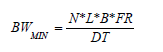
N= number of pixels per line
L=number of lines per frame
B=# Bits per pixel
FR=# frames per second
DT=(1-fraction of time lost to overhead requirements)
The liquid crystal display makes use of the twisted nematic affect to act as a ‘light gate’; either passing light through crossed polarizers or not. The light can be generated by a fluorescent lamp or led backlight. The relatively new Nook color technology provides a 7-inch 1024x600 pixel emissive display. One problem with this technology is that the emissions from lamps must compete with the ambient lighting conditions and reflections dominate the viewed image, making viewing and reading in outdoor environments nigh impossible, let alone desirable. As early as 2012, it was possible to purchase a 60 inch LCD TV with ‘bells and whistles’ for $3149.99 . Displays larger than 60 inches have not been considered because there is simply not enough space in the average home for these devices. LED backlit models are now capable of controlled backlight on-off switching, allowing for an ‘infinite’ dynamic contrast ratio. Common LCD display viewing angles are listed as high as 178 degrees, although they are realistically about 155-165 degrees as it is usually possible to sit within this viewable range. Vertical viewing angles are much less significant and therefore less controlled. Tilting LED displays in cellular phones vertically versus horizontally, for example, shows that the vertical viewing angle off normal incidence is much smaller than the horizontal one. LED backlit panels are thinner and consume less power than their fluorescent counterparts6. O’Sullivan et al argue that to maintain the customer’s viewing experience the color uniformity of a display must be within ±0.03 in the x-y chromaticity regime. Furthermore, they put forth that manufacturers must imbue their devices with LED luminosity degradation correction algorithms to drive the back-light unit harder, something without which LED-backlight, either direct-lit or edge-lit, will dim over time. In 2009, Samsung increased the frame rate of its most advanced displays by a factor of four, thus increasing the bandwidth requirements (Table 1).
Figure 1:An example of a Quantum Dot LED structure [5].

The organic light emitting diode makes use of the electroluminescence effect. It involves a multi-layered device structure wherein holes and charges are supplied by the source and drain. There are typically at least three layers: a hole transport layer, a charge transport layer, and a layer with reasonable mobilities of both charges and holes. Within this dual-transport region is where the exciton is formed and transferred to the emitting molecule7. An example of a hole transporting material is bis(triphenyl diamine), a charge conducting material is Alq, and NAPOXA is a good emitter molecule . For a more complete list of materials in organic devices, see the work of the Baldo group at MIT. Sometimes other layers are added confine exciton recombination to the doped emitter region (Figure 1). The emission spectra is principally determined by the electronic structure of the emitting molecule. The extent of pibonding and nature of the electron withdrawing/donating units off of the aromatic rings will alter the band gap energy, which dictates the frequency of the emission and, therefore, color. The internal quantum yield takes into account the number of photons generated per electron entering the device. Internal and external quantum yields are roughly relatable via the added resistance of the contacts. When the contacts are ohmic, the ratio of these converges to one. OLEDs may be crafted into flexible units, making them a prime target of wearable technologies8. One issue yet to be addressed with these displays is the dynamic mechanical analysis of how much stress and strain they can withstand over time before pixel fault. It has also been substantiated that e-ink display will emerge in a flexible format. Currently, OLEDs are limited by their size, most less than 31 in., and price. The limiting factor in OLED display size and cost is currently the polysilicon backplane which requires a power-intensive laser annealing step that is only possible for smaller display areas. A comparison of LCDs and OLEDs, image left9 demonstrates that OLED displays have a wider color gamut, increased brightness and contrast ratios than fluorescent lit LCDs. A comparison of LCDs and OLEDs, image left demonstrates that OLED displays have a wider color gamut, increased brightness and contrast ratios than fluorescent lit LCDs (Figure 2).
Foot Note:
6Sullivan EO, Pantalone R (2009) Issues in high-volume manufacturing of large screen LED backlit lcds. Information Display: 22.
7 Dodabalapur A (1997) Organic light emitting diodes. Solid State Communications 102(2-3): 259-267.
8 Donelan J (2009) Flexible displays come into their own at display week. Information Display 3(9): 24.
Figure 2:A comparison of LCDs and OLEDs.

Plasma displays
Plasma displays utilized charged ion gasses to emit light. These devices have wider viewing angles and higher refresh rates than LCDs but can ‘burn-in’-when a latent image is present over longer exposures of pictures-and phosphors can degrade over time, resulting in decreased luminosity10. However, the lifetimes are still longer than CRT technology-11,000hrs in CRT vs. over 100,000 hrs in plasma11. Plasma displays consumer more power than do LCD technologies, have altitude limitations because they are based upon gas emissions, generate background frequency noise that interferes with HAM, WL and RFI devices within short ranges (Figure 3). These panels are not manufactured at sizes smaller than 37 inches. Plasma displays are being phased out of production since LCDbased devices have supplanted them. Similarly, OLEDs have quickly supplanted LCDs.
Figure 3:The noise generated by a Panasonic 42 in. PDP (arbitrary signal units on the y axis vs. frequency in Hertz on the x axis as measured by a HP Network Analyzer.

E-ink utilizes charged color toner particles and utilizes the electrophoretic effect. These particles reorient in an applied electric field. Light reflects off of the particles to produce a bistable image. The bistable image is persistent in time without significant power requirements. Since the light is provided externally and the only voltage required is during the image formation, these devices have extremely low power requirements. The refresh rates of e-paper are not currently fast enough for video display. Devices such as the Amazon Kindle and Barnes and Noble Nook require charging as infrequently as once per ten days.
Many of these devices have come to incorporate LCD touch screens to provide a fast-response color interface required for common functions such as title selection, information input and menu functions. This reinforces the concept that devices fulfill a niche role. There are two major embodiments of e-ink technology are:
(i) Wherein there are separate particles to display black and white pigmentation and
(ii) Wherein a single particle that is hemi-spherically black and hemi-spherically white simply rotates in the electric field.
Boarders books filed for chapter 11 bankruptcy and closed over 200 stores in February 2011. The New York Times has started factoring electronic purchases into its widely reported Best Seller Lists. It is clear that e-ink is quickly replacing print paperback books and newspapers. Its ease of delivery of digital content along 4G and wireless networks makes it such consumers no longer need to travel to a physical book store to purchase a book. Consumer theory states that a product will be replaced when it provides the same service at a similar cost with reduced required actions on the part of the consumer. Furthermore, the implementation of digital e-book sharing allows users to share stored literature with friends via email link for a limited amount of time. This functionality addresses the fact that printed books can simply be shared by people through direct physical contact. Since a user is much less likely to lend someone a device that casts $150-200, this allows engaging literature to maintain it social value (Figure 4).
Foot Note:
9 Hwang C (2008) Facts and figures from centrum fürbüroautomation, informationstechnologie und. Telekommunikation Conference Summary.
10 Ranjan P,McGraw H (2006) Principles of multimedia.
11 Ibrahim KF (2007) Newnes guide to television and video technology. Newnes.
Figure 4:TOrthostereoscopic conditions.

Three dimensional televisions make use of several biological and neurological phenomena. Most essentially the process of binocular parallax; the relative position of depth based upon a shift in left-right retinal images. 3D televisions require more power to operate than their 2D counterparts. The image to the left12 depicts the ideal 3D viewing experience, wherein
(i) The distances between the eyes and the cameras filming the multiple perspectives are equivalent,
(ii) Viewing is at normal incidence, and
(iii) Viewing is from the same distance from the recorded object as the camera’s were and of a similar scale.
Figure 5:A Chart detailing the image distortions as a result of incorrect camera separation with screen height and observation distance [3].

Of course, the third premise is largely untrue due to both technological limitations and the size of living rooms and other venues within which these displays must fit. Manufacturing limitations allow for device synthesis with diagonal size much larger than the average American man (70 inches)13. Therefore, the authors cite image ghosting, crosstalk and size misperception (Figure 5 & 6) from viewing images on displays that are not properly sized with respect to the displayed image and the camera distance, d1, is not appropriate to the d2 to d3 proportions. One of the visual irregularities in 3D display technologies that affect everyone are vertical displacement, rotation error and size inconsistency.
Foot Note:
12 Javidi B, Okano F, Sparger (2002) Three-dimensional television, video, and display technologies, Technology & Engineering.
13 (2010) National health and nutrition examination survey.
Figure 6:Simulation results for color image. (a) Original image. (b) Image with Ci=0.5, r=2.2. (c) Image with Ci =0.75, r=2.2. (d) Image with Ci=1, r=2.2.

One question that has been proposed is whether there exists enough frequency bandwidth to properly transmit high resolution 3D content. This was addressed by Javidi et. al.ref A sample calculation is performed in the appendix (Table 2-4) and it is possible to transmit a comparable channel amount of 3D content as 2D content over the air. There exist only a handful of over the air 3D stations, however, due to the fact that 3D televisions have not yet become common. The early adopters are able to get their “fill” of 3D content through private networks such as cable and Direct TV.
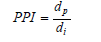
Table 2:Computation for Diagonal Pixel Resolutions (DPR) and Pixels per Inch (PPI) for various resolutions and screen sizes.

Table 3:Computation of the display sizes from resolutions and aspect ratios.

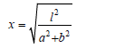
l= diagonal size (in)
a:b= horizontal:vertical pixel size ratio
ax=horizontal size (in)
bx=vertical size (in)
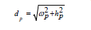
wp= horizontal pixels
hp=vertical pixels
dp= pixels along main diagonal.
Table 4:Computation of the horizontal and vertical pixel resolutions in pixels per inch.

The human eye is very different from the electronic and engineered equipment discussed so far. Display devices are manufactured to exacting standards and if a particular device is not within accepted parameters, then it is discarded. This is not the case with the human anatomy. Variances in perceptions such as astigmatism, strabismus and amblyopia alter display perception causing a distortion of linear perspective-depth uniformity across the display for items at equal distances from the observer-and motion parallax-the ability to perceive an image when the position of the observer changes. For example, some people are particularly susceptible to headaches after viewing TV due to these effects. Their bodies are reacting badly to the fact that the images on the screen are differing from their normally perceived world. 3D devices, in particular, have issues with this. Another group of people, estimated at approximately 4-10 percent of the American population, cannot resolve the images from the left and right eye into a single 3D vision. Therefore, there is a need for new display technologies that can project non-3D and 3D content simultaneously for a wider audience.
FEDs
Field emission displays function in a very similar way to CRT televisions. There is an electron beam that traces the image along the phosphor cells and whether or not it is on or off dictates whether or not the colored phosphor is excited and emits. Instead of a single electron gun, there is an electron gun for each colored sub-pixel. This allows for the device to be much thinner than a traditional CRT monitor. The advantages of this technology are high contrast levels and fast response times. Theoretically, this device can consume just over half of the LCD technology. Sony, Sharp and Candescent Technologies have halted their research on the technology in the last few years and, although having successfully made functional devices, never brought them to market. These devices have been known to have issues with charge injection with barium oxide contacts due to the inability to find low enough work function materials.
Dead pixels, gamma correction, wireless displays & other advanced features
Dead pixels can be either dead off, dead on, or gamma correction shifted14. Dead off is the least detrimental to the image quality. Dead on pixels and gamma correction shifted pixels are glaringly obvious. Dead pixels are usually caused by defects in the transistor underlying the optically active layers of the device. Dead on LCD pixels are due to a transistor that has had its power source cut, such that it continually allows light to pass. Dead off LCD pixels have a short somewhere in the circuit that keeps power contently flowing, this occluding light. It is important to distinguish between a stuck pixel and a dead pixel. A stuck pixel is one in which a temporary, reversible defect in the transistor or LC element is present. These can be corrected by professionals via physical, temperature and electrical stimulation. However, dead pixels are permanent and cannot be repaired this way. One to two dead pixels of any condition are within acceptable parameters for a manufacturing company to sell a display.
QD LEDs
Quantum dot light emitting diodes have a similar structure to OLEDs, except that instead of an organic dye emitting light in response to exciton recombination, a quantum dot is doing so. The quantum dot compounds emit light as a function of the particulate size instead of the material band gap, so a single quantum dot compound can be used for the entire device.
Gamma correction defined
Gamma correction is a mathematical procedure to correct for the differences in voltage signals and luminosity coding between the recording device and the emitting device15. The sensors in most camera devices convert the intensity and color information into a voltage signal, which varies linearly with luminance. The luminance of the emitting technology may, however, have a nonlinear optical response with respect to input signal, therefore the display must correct for this deviation with the gamma correction. Typical gamma correction compressions -as the camera may automatically encode signals with gamma correction - or decompressions are governed by the following mathematical relationship:
Gr[k]=Ci*(k/255)^r;
r=gamma correction factor (approx. 1/2.2 for decoding and compression and 2.2 for decompression A0 is a scaling, normalization factor to alter the frequency from transmission to the particular device signal. The image to the left depicts the affects of the gamma correction power r, on the displayed image.
Foot Note:
14 An J, Lee W (2007) Adaptive detection and conealment algorithm of defective pixel. Signal Processing Systems, 2007 IEEE Workshop.
15 Wang Z, Liang Z, Liu C (2009) A real-time image processor with combining dynamic contrast ratio enhancement and inverse gamma correction for PDP Displays 30: 133-139.
The dynamic range represents the ratio of the highest value of a particular quality to the lowest value. In the context of photographic and video imaging, high dynamic range computations16 allow the display to improve the contrast present in a frame through linear combinations of a shifted overly-luminous image and an underluminous image. The image to the lower left has had HDR and gamma correction algorithms applied.
Wireless displays
New standards such as WiMax will allow for the local transmission of a High Definition digital video signal from a device-laptop or blue ray player-to a display device wirelessly, similar to how an internet router dispenses internet connectivity wirelessly. One challenge that resulted in the separation of these technologies is the competition in routers between digital video content streaming-HD Netflix, Hulu, SurfTheChannel, Pandora and SideReel-or networked storage-AppleTV, Boxee, Pogoplug or Ubuntu XMBC-and other internet traffic - browsing, file transfers, email, and other content.
Advanced features
The most luxury and feature-intensive displays include Ethernet ports, multiple USB ports, wireless internet connectivity, Energy Star certifications, 2D to 3D up-conversion technology, and automatic blur reduction algorithms. These features add to the cost of information display technologies. Consumers pay for the device that will offer them the largest, pixel dense, high contrast displays. Other functions that are on the cutting edge, such as those mentioned immediately above are saved for the early adopters, and are usually too expensive for the average consumer.
Conclusion
As time goes on, industry will find ways to make these devices cheaper, thinner, lighter and more power efficient while maximizing their color gamuts, viewing angles, and contrast ratios. Adding other functions that improve connectivity with other electronics- Ethernet ports, Wi-Max, and WiFi, improve social impact through content generation and sharing-i.e adding video cameras to TVs for video conferencing, and that are unforeseeable but drastically improve viewing experience-as 3D was in the 1980s-will alter the way that we interact with people and information. These devices will become essential moving forward in affecting way that we communicate, solve real and complex problems, and continue to supply the global population with relevant, up-to-date information on world events.
Foot Note:
16 Myszkowski K, Karol M (2008) High dynamic range video synthesis lectures on computer graphics and animation. Morgan & Claypool Publishers, UK.
References
- Accurate modeling of LED colors (2005) A scientific approach. Ian Ashdown. LEDs Magazine, Europe.
- McGraw H (2000) Video display engineering whitaker.
- Seminar Lecture Notes from Washington State Convention Center (2010) Society for information display.
- (2007) Spontaneous-emission control by photonic crystals and nanocavities Source. Nature Photonics 1(8): 449-458.
- Anikeeva P, Halpert J, Bawendi M, Bulovic V (2009) Quantum dot lightemitting deices with electroluminescence tunable over the entire visible spectrum. Nano Letters 9(7): 2532-2536.
- Tsutsui T (2002) A light-emitting sandwich filling . Nature 420(6917): 753-755.
- Malacara D (2002) Color vision and colorimetry theory and applications. SPIE Publications, USA.
© 2018 Guy Francis Mongelli. This is an open access article distributed under the terms of the Creative Commons Attribution License , which permits unrestricted use, distribution, and build upon your work non-commercially.
Editor In Chief


.jpg)


Signup for Newsletter

Quick Links
 Editorial Board Registrations
 Submit your Article
 Refer a Friend
 Advertise With Us
Our Recent Edition

.jpg)


Top Editors


.jpg)


.bmp)
.jpg)
.png)
.jpg)


.jpg)


.png)

.png)


.png)


Financial Support

Sponsors

Latest e-Books

Latest Video

 a Creative Commons Attribution 4.0 International License. Based on a work at www.crimsonpublishers.com.
Best viewed in
a Creative Commons Attribution 4.0 International License. Based on a work at www.crimsonpublishers.com.
Best viewed in