
- About Us
- Information
-

The Author ensures that the research has been conducted responsibly and ethically with adherence to all relevant regulations. read more..
- For Authors
- For Reviewer
- Manuscript Guidelines
- Membership
- Publication Ethics
-
- Journals
- Reprints
- e-Books
- Videos
- Policies
- Contact Us
 COVID-19
- Submissions


Full Text
Research & Development in Material Science
Refinement of Dendrite Structure in Single-Crystal Castings of Superalloys
Hongyuan Sun, Dexin Ma*, Zhongyuan Sun, Jianhui Wei, Xiaoyi Gong and Yunxing Zhao
1State Key Laboratory of Powder Metallurgy, Central South University, China
2Shenzhen Wedge Aviation Technology Co., China
*Corresponding author:Dexin Ma, State Key Laboratory of Powder Metallurgy, Central South University, Changsha 410083, China
Submission: August 28, 2025;Published: September 17, 2025

ISSN: 2576-8840 Volume 22 Issue 3
Abstract
The conventional Bridgman process for fabricating single-crystal superalloy castings is constrained by low temperature gradient and coarse dendrite structures. In this study, a novel conformal insulation technique was devised to overcome these limitations. The approach involved incorporating insulation materials within the central region of the ceramic shell cluster and applying conformal insulation plates to the mold periphery, effectively suppressing furnace heat loss and enhancing the temperature gradient during solidification. The numerical simulations and experimental casting trials on both single-crystal rods and turbine blades were carried out. It was found that this new technique could more than double the attainable temperature gradient. As a result, the morphology of the solid–liquid interface evolved from inclined to planar, the extent of the mushy zone was substantially reduced, and dendrite refinement within the single-crystal castings was significantly promoted. These results demonstrate the effectiveness of the proposed process in improving the structure control and overall quality of single-crystal superalloy castings.
Keywords:Superalloy; Single crystal; Directional solidification; Temperature gradient; Dendrite refinement
Introduction
Due to their excellent high-temperature properties, Nickel-based superalloys have become the preferred materials for manufacturing key components such as turbine blades of aeroengines and gas turbines [1,2]. At present, the Bridgman process is widely employed worldwide for the fabrication of Single-Crystal (SC) superalloy turbine blades [3-5]. In this process, a ceramic shell mold placed in a Bridgman furnace is preheated to a prescribed temperature in the heating chamber, followed by pouring molten superalloy into the mold cavity. The mold is then withdrawn from the heating zone, through a baffle, and into the cooling zone, enabling progressive solidification from the bottom to the top of the casting and forming a columnar grain structure essentially aligned with the axial direction. By introducing a spiral grain selector at the casting bottom, a SC grain can be selected to propagate into the cavity, thereby producing a SC casting. The Bridgman method is characterized by relatively simple casting equipment, stable and reliable operation, and technological maturity, which together have made it the most commonly adopted technique for manufacturing SC superalloy blades. Nevertheless, this casting approach also exhibits notable drawbacks, including a low temperature gradient, slow cooling rate, and a high susceptibility to grain defects and coarsening of the microstructure in SC castings. Over the years, considerable efforts have been devoted to improving the conventional directional solidification process. Among these, the liquid metal cooling (LMC) technique [2,6,7] has been demonstrated to effectively increase the temperature gradient and cooling rate, thereby refining the microstructure and enhancing the properties of SC castings. However, the widespread engineering application of LMC in the production of SC superalloy blades has been limited by the high cost of the equipment and the complexity of the process.
Based on the conventional Bridgman process, we have developed a conformal insulation technique to enhance the temperature gradient [8]. In this study, the new technique was applied to the fabrication of SC rods and turbine blades, in order to investigate its effect on dendritic refinement. Figure 1(a) shows the conventional Bridgman process (hereafter referred to as Process A), while Figure 1(b) depicts the modified process (hereafter referred to as Process B). The key feature of Process B is the introduction of flexible conformal insulating materials into the gaps between the central pillar and the adjacent castings, forming an internal insulation layer. Additionally, on the outer surface of the shell mold, a conformal insulation layer, fitted to the mold geometry, can be added on top of the original annular baffle (not shown in the figure). As illustrated in Figure 1(b), Process B essentially eliminates the through-channel in the central region of the mold shell, thereby preventing open heat dissipation from the upper heating zone to the lower cooling zone of the furnace. At the same time, it reduces the gap between the mold shell outer surface and the surrounding baffle. With such conformal insulation measures, the furnace bottom is effectively sealed, leading to a significant reduction in thermal energy loss. More importantly, this configuration forces the heat in the heating zone to be conducted downward only through the casting and mold shell, thereby effectively enhancing the temperature gradient during the solidification of the SC castings.
Figure 1:Schematic illustration of the shell molds used in the conventional process (Process A) (a) and the new process (Process B) (b).

The Nickel-based SC superalloys employed in this work are DD419 and WZ30, whose chemical compositions are listed in Table 1. Using relevant thermodynamic software, the liquidus temperature (TL) and solidus temperature (TS) of the two alloys were calculated and are also included in Table 1. It should be noted that ΔTL-S = TL-TS represents the solidification interval of the alloys, corresponding to the temperature difference between the top and the bottom of the mushy zone during solidification.
Table 1:Nominal composition and characteristic temperature of the applied Ni-based superalloys.

First, two sets of cylindrical SC rods of alloy DD419, each with a diameter of 15mm and a length of 180mm, were fabricated using Processes A and B, respectively. Each rod was equipped with a spiral grain selector at the lower end and arranged around a central pillar to form an annular configuration. The ceramic shell molds were prepared by a conventional lost-wax process. For the traditional Bridgman process (Process A), the mold shown in Figure 1(a) was directly employed. For the modified process (Process B), the space surrounding the central pillar was filled with flexible insulating materials on the inner side of the mold (Figure 1(b)), and conformal insulation plates fitted to the outer contour of the mold were additionally applied. The directional solidification experiments were carried out in a vacuum furnace manufactured by ALD, Germany (Model: VIM-IC/DS/SC). For both sets of experiments, the mold preheating temperature and pouring temperature were set to 1500 °C, and the withdrawal rate was fixed at 3.0mm/min. Under these identical casting parameters, the temperature gradients at the solidification front of the rods were measured to be 1.9 °C/mm and 4.9 °C/mm for Processes A and B, respectively. In other words, the temperature gradient achieved by the new process (Process B) was more than twice that of the conventional process (Process A).
Prior to the casting experiments, the solidification process of the SC rods was numerically simulated using ProCAST software. The simulation began with geometric modeling and meshing of all components in the solidification system, followed by the input of the thermophysical properties of the various materials, as well as the boundary and initial conditions of the solidification process. As the most important thermophysical property, the heat conductivity of the relevant materials in dependence on temperature is shown in Figure 2.
Figure 2:The heat conductivity of the relevant materials including the conformal isolation material.

The heat transfer equation employed [9] is:
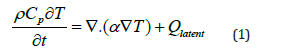
where ρ is the material density, Cp is the specific heat capacity, T is the temperature, t is the time, α is the thermal conductivity, and Qlatent represents the latent heat release. The corresponding solidification kinetics are described by the well-known Scheil model [10]:
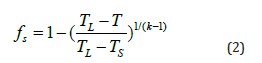
where fs is the solid fraction, TL is the liquidus temperature, TS is the solidus temperature, and k is the solute partition coefficient at the solidification front. By solving the above equations, the temperature field and the evolution of the solid fraction throughout the casting can be obtained.
Figure 3(a) shows the simulation results under Process A. It can be seen that the solidification front corresponding to the liquidus temperature TL rises approximately 40mm above the top of the insulation baffle and exhibits a pronounced inclination, which is highly unfavorable for directional solidification of the casting. The temperature interval of the mushy zone is ΔTL-S = 84 ℃ (Table 1) with a vertical width of ΔZ, so the local temperature gradient can be calculated as G = ΔTL-S/ΔZ. Since the undercooling ahead of the dendrite tip is negligible during normal directional solidification, the isotherm at the liquidus temperature TL indicates the position of the solidification front. On the inner side of the rod facing the central pillar, the mushy zone corresponding to the solidification interval ΔTL-S has a width of approximately ΔZ = 46mm, yielding a local temperature gradient of G = 84/46 = 1.8 ℃/mm. On the outer side facing the heater, the mushy zone width is ΔZ = 36mm, giving G = 84/36 = 2.3 ℃/mm. Therefore, the average temperature gradient of the SC rod is approximately G = 2.1 ℃/mm, which is consistent with measurements under production conditions, where the temperature gradient in the conventional directional solidification process is around 2 °C/mm.
Figure 3:Simulated temperature fields during the solidification of rods in Process A (a) and Process B (b).

Figure 3(b) shows the simulation results under Process B. The solidification front (TL) is located near the height of the insulation baffle and is essentially planar without noticeable inclination, providing favorable conditions for directional solidification. The mushy zone widths on both the inner and outer sides of the rod are approximately equal, ΔZ = 18mm, resulting in a local temperature gradient of G = 84/18 = 4.7 ℃/mm. This value is more than twice that obtained under the conventional process (Figure 3(a)).
The simulation results indicate that the application of the Process B produces significant improvements, which can be summarized as follows: (1) the position of the solidification front in the rod is adjusted from being well above the insulation baffle to near the baffle; (2) the morphology of the solidification front changes from highly inclined to essentially planar; and (3) the width of the mushy zone during rod solidification is reduced by more than half, resulting in a temperature gradient that has more than doubled. These enhancements in solidification conditions are highly beneficial for the directional solidification of SC superalloy castings.
The SC rods produced using Processes A and B are hereafter referred to as Rods A and B, respectively. Figure 4(a1) shows a macroscopic view of the A-group rods after etching, in which pronounced chain-like freckles are observed on the surfaces. Figure 4(a2) presents a magnified view of a single Rod A, clearly highlighting the presence of freckles (circled in the figure). In contrast, Figure 4(b1) shows the B-group rods, all exhibiting sound external appearances, and Figure 4(b2) provides a magnified view of a single Rod B, where no freckle defects are detected on the surface. The formation of freckles in directionally solidified castings is primarily attributed to the low temperature gradient [11-14]. By employing Process B, the temperature gradient is significantly increased, resulting in the effective elimination of freckle formation in SC superalloy castings.
Figure 4:Macroscopic photos of SC rods produced by Process A (a1) and Process B (b1), and corresponding magnification of the rod surface (a2, b2).

Figures 5(a) & 5(b) show the cross-sections of SC Rods A and B, respectively. It can be seen that the microstructure of Rod B is free of freckle defects, and the dendrite structure is significantly refined. As a characteristic scale of the dendrite structure, the primary dendrite arm spacing (λ) was measured on the cross-sections of both rods. The average λ-value of Rod A was 406 μm, whereas Rod B exhibited a λ of only 262 μm, representing a reduction rate of 35%.
Figure 5:(a) Process A, showing coarse dendrites and freckle defects, (b) Process B, showing refined dendrites and no defects.

In this study, SC turbine blade castings were also fabricated using the conventional Bridgman-Process A and the improved Process B, as schematically illustrates in Figure 1. The material employed was WZ30 alloy, whose composition and characteristic temperatures are listed in Table 1, with a solidification interval of ΔTL-S = 61 °C. The blades produced by the two processes are hereafter referred to as Blade A and Blade B. Due to the much more complex geometry of the blades compared to the cylindrical rods, the filling of internal insulation materials and the fabrication of external conformal insulation plates were also more intricate. Figure 6 presents the simulated temperature fields of the blade castings, where the dark region represents the mushy zone between the liquidus (TL) and solidus (TS) temperatures. During the conventional directional solidification of Blade A (Figure 6(a)), the solidification front is highly inclined. In particular, on the inner side of the blade facing the central pillar (left side), the mushy zone width ΔZ reaches 48mm, corresponding to a temperature gradient of only G = 61/48 = 1.3 ℃/mm. On the opposite side, facing the heater (right side), direct radiation from the heater raises the temperature significantly, resulting in a nearly planar solidification front and a narrower mushy zone (ΔZ =17mm), with a corresponding temperature gradient of G = 61/17 = 3.6 ℃/ mm. As shown in Figure 6(a), the conventional Bridgman process provides poor directional solidification conditions, particularly on the inner side facing the central pillar, where the solidification front is severely inclined, the mushy zone is wide, and the temperature gradient is low. These conditions are unfavorable for directional solidification and promote the formation of structure defects such as stray grains and freckles. Moreover, the low cooling rate results always in coarse dendritic microstructures, even if SC castings are obtained.
Figure 6:Simulation results of SC blade solidification in Process A (a) and Process B (b).

As shown in Figure 6(b), the solidification conditions of Blade B are significantly improved, characterized by a marked reduction in the inclination of the solidification front and a narrower mushy zone. On the inner side of the blade, the mushy zone width decreases to ΔZ = 22mm, resulting in an increased temperature gradient of G = 61/22 = 2.8 ℃/mm. On the outer side, the mushy zone width is reduced to only ΔZ = 8.4mm, corresponding to a temperature gradient of G = 61/8.4= 7.2 ℃/mm. In other words, the temperature gradient G on both the inner and outer sides of Blade B is more than twice that of Blade A. The simulation results indicate that the new process provides a more stable and vertically aligned temperature field, offering favorable thermodynamic conditions for directional solidification and enabling the production of highquality SC castings.
Figures 7(a1) & 7(a2) show the cross-section and corresponding magnified view of the airfoil of Blade A. The dendrite structure is relatively coarse, with an average primary dendrite arm spacing of λ = 420μm determined using the area-averaging method. Numerous bright γ/γ’ eutectic clusters are observed between the dendrites, and interdendritic microporosity is clearly visible (circled in the figures). In contrast, the dendrite structure of Blade B is significantly refined, as shown in Figures 7(b1) & 7(b2), with a measurement result of λ = 258μm, representing a 38% reduction compared to Blade A. The refinement of the dendrites leads to a notable decrease in both the fraction and size of γ/γ’ eutectic clusters, which are more dispersed and uniformly distributed, facilitating their complete dissolution during subsequent heat treatment. Furthermore, the increased temperature gradient and shortened mushy zone improve interdendritic feeding, such that interdendritic microporosity was hardly observed in Blade B at the same magnification (Figure 7(b2)).
Figure 7:Cross-sections and corresponding magnified views of SC blades A (a1, a2) and B (b1, b2).

On the cross sections of the cylindrical samples A and B, the volume fraction of γ/γ’ eutectic (fE) were measured to be 9.97% and 8.20%, respectively. It should be indicated that the increase in the temperature gradient leads to the refinement of the dendrite structure including the interdendritic γ/γ’ eutectic, but no new phases were observed in the as-cast structure of rods and blades produced in the process B.
After solution and aging heat treatment under the same conditions, samples A and B were cut from the upper section to prepare test samples for stress rupture property testing at 850 °C/650MPa and 1050 °C/190MPa. In total, twelve testings were carried out, in which three A-rods and three B-rods were tested under each condition, respectively. The crystal misorientation of the samples were less than 5 degrees, and the measured stress rupture life is shown in Table 1. Under the test condition of 850 °C/650MPa, the mean stress rupture lives of sample A and sample B were 115.3h and 144.0h, respectively, with sample B showing a 24.9% improvement over sample A. Under the test condition of 1050 °C/190MPa, the mean stress rupture lives of sample A and sample B were 89.1h and 93.7h, respectively, showing a 5.2% improvement of sample B over sample A. This indicates that refining the dendrite structure can improve the stress rupture property of SC castings, but the improvement in high-temperature stress rupture property is not as significant as that at mid-range temperatures.
It should be noted that the above-described conformal insulation technique is very suitable for production of SC rods and small turbine blades of simple geometry. For big blades or vanes with complex shapes, it is relatively difficult to insert the insulating materials into the gaps between the central pillar and the adjacent castings. For large blades, the cooling conditions of widely expended platforms could become worse due to the surrounding insulating materials. These problems could be solved during further improvement of this new processes.
In summary, this work employs a self-developed conformal insulation technique, in which insulating materials are filled in the central region of the mold assembly and conformal insulation plates are added to the exterior of the mold. As a result, the solidification conditions were significantly improved. This new technique was applied to the fabrication of SC rods and turbine blades of superalloys. Based on numerical simulations and casting experiments, it was found that the temperature gradient during SC solidification could be doubled. The solidification front in SC castings became planar rather than inclined. The mushy zone was shortened, and freckle defects were eliminated. The primary dendrite arm spacing, as a characteristic scale of the dendrite microstructure, was reduced by more than one-third. Both the fraction and size of γ/γ’ eutectic clusters and interdendritic microporosity in the as-cast microstructure were significantly decreased. These results demonstrate a pronounced refinement and optimization of the dendrite microstructure in SC superalloy castings, leading to a substantial improvement in the quality of SC products. Due to dendrite structure refinement, the stress rupture life of the superalloy samples was evidently improved, especially at medium temperature.
Acknowledgment
This research was funded by “Shenzhen Science and Technology Program (JSGG20220831092800001)”and “Advanced Materials - National Science and Technology Major Project (2025ZD0609600)”.
References
- Meetham GW (1981) The development of gas turbine materials. Applied Science Publishers, London, UK, pp. 89-119.
- Reed RC (2008) The superalloys: fundamentals and applications. Cambridge University Press, UK.
- Versnyder FI, Shank ME (1970) The development of columnar grain and single crystal high temperature materials through directional solidification. Materials Science and Engineering 6(4): 213-47.
- Pratt DC (1986) Industrial casting of superalloys. Materials Science and Technology 2(5): 426-435.
- Ma DX (2018) Novel casting processes for single crystal turbine blades of superalloys. Frontiers of Mechanical Engineering 13 (1): 3-16.
- Elliott AJ, Pollock TM, Tin S, King WT, Huang SC, et al. (2004) Directional solidification of large superalloy castings with radiation and liquid-metal cooling: A comparative assessment. Metallurgical and Materials Transactions A 35A: 3221-3231.
- Shalin RE, Pankratov VA (2013) Single crystal casting of nickel-base superalloys by directional rapid solidification. Metallurgical Science and Technology 10: 3-9.
- Sun HY, Ma DX, Zhao YX, Wei JH, Gong XY, et al. (2025) Dendrite structure refinement and mechanical property improvement of a single-crystal superalloy. Metals 15: 295.
- Jackson KA, Hunt JD (1975) A dendritic growth model for solidification of a binary alloy. Acta Metallurgica 23(11): 1235-1244.
- Kurz W, Fisher DJ (1992) Fundamentals of solidification. Trans Tech Publications, Switzerland.
- Giamei AF, Kear BH (1970) On the nature of freckles in nickel base superalloys. Metall Trans 1: 2185-2192.
- Tin S, Pollock TM (2004) Predicting freckle formation in single crystal Ni-base superalloys. J Materials Science 39: 7199-7205.
- Ma DX, Dong ZH, Wang F, Dong HB (2020) A phenomenological analysis of freckling in directional solidification of Ni-base superalloys: the role of edge and curvature in casting components. Metall Mater Trans 51A (1): 88-92.
- Ma DX, Zhao YX, Xu WT (2021) Freckle formation affected by geometry features of single crystal superalloy castings. Res Dev Material Sci 15(5). RDMS.000873.
© 2025 © Dexin Ma. This is an open access article distributed under the terms of the Creative Commons Attribution License , which permits unrestricted use, distribution, and build upon your work non-commercially.
Editor In Chief


.jpg)


Signup for Newsletter

Quick Links
 Editorial Board Registrations
 Submit your Article
 Refer a Friend
 Advertise With Us
Our Recent Edition

.jpg)


Top Editors


.jpg)


.bmp)
.jpg)
.png)
.jpg)


.jpg)


.png)

.png)


.png)


Financial Support

Sponsors

Latest e-Books

Latest Video

 a Creative Commons Attribution 4.0 International License. Based on a work at www.crimsonpublishers.com.
Best viewed in
a Creative Commons Attribution 4.0 International License. Based on a work at www.crimsonpublishers.com.
Best viewed in