- Submissions

Full Text
Research & Development in Material Science
Characterization of the Damage Mechanism of Composites against Low Velocity Ballistic Impact Using Computed Tomography (CT) Techniques
Emre Yılmaz, Mehmet Gökhan Gökçen, Alparslan Demirural and Tarık Baykara*
Department of Mechanical Engineering, Doğuş University, Turkey
*Corresponding author: Tarık Baykara, Department of Mechanical Engineering, Doğuş University, Acıbadem, İstanbul, Turkey
Submission: September 02, 2017; Published: October 23, 2017

ISSN : 2576-8840Volume1 Issue5
Abstract
Low velocity impact damages are particularly considered as risky and dangerous since the detection of the damage from the surface is almost impossible for extensive evaluation. The mechanisms of penetration and damage for E-glass reinforced polyester resin composite which was hit by a low velocity projectile has been investigated using computed tomography (CT) scanning techniques. Laminated, 11 mm thick plates with [0°/90°] ply architecture with 18 layers were impacted by a 9x19mm FMJ Round Nose 8g bullet with a speed of 380m/s. Since the low velocity impact of the bullet is well below the ballistic limit only a partial penetration has occurred and the kinetic energy is fully absorbed following some local matrix cracking, fiber fractures, delamination and friction-erosion. Computed Tomography (CT) technique is found to be a powerful technique that the full extent of the damage progression in 3-D can be visualized through the interfaces of the composite laminates.
Introduction
Fiber reinforced polymeric materials i.e. composites are attracting continuous attention for ballistic applications due to their strength-to-weight-ratio, high stiffness, high tensile strength, high toughness and environmental resistance. Composites are combinations of two or more different high strength reinforcing materials in different shapes and geometries (e.g. fibers) embedded in another ductile material called matrix phase. Such combination results in properties superior to each of the individual components. That kind of composites are commonly used as thick panels made of laminates that have good damage tolerance against repeated impacts with low-to-high energy. Damage tolerance of composites is important in both ballistic armour and structural applications particularly for lightweight vehicles against high and low velocity impacts. Damage mechanisms such as delamination and matrix and fiber cracking/breakage are common as out-of-plane impacts occur with low-to-high energy. There has been extensive research on the damage mechanism of composites under high energy or ballistic impact both theoretically and experimentally [1-5].
Both fiber and matrix properties are crucial for the impact and damage tolerance of composites along with the amount, configuration, geometry and composition of these phases. As shown by the studies elsewhere, optimum percentage of fibers, toughened matrix phase and careful processing help decreasing the damage and failure of such structures [6-10]. While the impact behavior and damage mechanisms of composites have been extensively investigated, there have been still very few study conducted to address the detailed steps for the impact mechanism and the effect of processing.
The ballistic performance i.e. penetration resistance of a composite depends upon various factors that are acting simultaneously when an incoming projectile impacts on the surface. The properties and the structures of the fiber and the matrix phases, configuration of fabric architecture, geometry and the speed of impacting projectile, thickness and the number of plies are some of these parameters affecting the impact mechanism and the damage of the composite panel. Various fiber materials of aramid and ultra-high modulus polyethylene base with trade names such as Kevlar, Dyneema, Spectra, and Twaron are being used in armour applications along with carbon and glass fibers (E-glass, S-glass etc.). These fibers are used in woven and non- woven forms as single and multi-layered plies. As for the matrix, both thermoset and thermoplastic resins are being used including phenolic resins, vinyl ester, polyurethane, epoxies, polyethylene etc.
It was repeatedly indicated that the penetration mechanics of composites is a very complex process which requires involvement of fiber and matrix interaction, strain rate of materials and friction and erosion. Here, projectile-material interaction and the strain to failure are critical factors that determine the energy absorption of composites. In composites, dominant failure mode is brittle fracture in micro scale along with a very limited plastic deformation in the ductile matrix phase. In this respect, fiber failure is the controlling mechanisms for the energy absorption process during the impact. Upon the impact of projectile, fiber failure (instantaneous mechanisms of rupture, breakage, crush and pull out) and matrix cracking occur to absorb kinetic energy leading either to full collapse of the material or stopping the incoming bullet. It is reported that the projectile penetrates the surface creating compressive and shear stresses and eventually slows down. If the structure resists to such instant impact loading, the projectile also collapses and erodes to fracture in fragments, pieces and cause tensile elongation, delamination and fiber pull out [9,10].
Low velocity impact damages are particularly considered as risky and dangerous since the detection of the damage from the surface is almost impossible for extensive evaluation thus causing great concerns for the users in critical applications such as defense and security. The complex modes of the damage for low velocity impacts include fiber breakage, matrix cracking, matrix crush and delamination [11].
Various techniques with differing models were being applied to evaluate the complete damage mechanisms. However, it should be noted that such approaches were useful for macro-scale and cannot explain the damage mechanism in micro-scale. Various damage modes such as fiber pull-out, fiber/matrix debonding, and progression of delamination are still in needs of investigation for further details. In this regard, computed tomography (CT) technique is a strong tool to fully visualize the local damage region, path of delamination through crack propagation, projectile-target interaction, fiber failure behavior and others.
In this study, low velocity impacted (app. Speed of 380m/s) laminated composite panel by a 9mm diameter projectile was investigated using computed tomography (CT) technique to evaluate the complete penetration and damage mechanisms. It is a fact that computed tomography (CT) is found to be such a powerful technique that it visualizes the full extent of the damage progression in 3-D along with the distribution of the remnants of the fragmented bullet through the interfaces of the composite laminates.
Experimental
Figure 1: Cross sectional micrograph of the laminated composite. Blackish bands show the parallel fiber layer (in 0°) and the remaining lighter areas show the fiber layers in transverse direction (in 90°).

E-Glass fiber laminates in basket-woven forms (0°/90°) and polyester resin are used for the composite structure. Total 18 plies along with the catalyst mixed polyester resin (with a 65% ideal fiber content) are laminated first via careful hand layup technique to manufacture panels with dimensions 40x40x11mm. Panels were then compressed under a 60 tons hydraulic press for 30 minutes applying approximately 100 bar pressure. Pressed panels were then post- cured in an oven at 85 °C for 2hrs. Cross sectional view of the laminated composite indicates a pore and void free structure as shown in Figure 1.
Ballistic tests
Ballistic testing of the composite panel was conducted using 9-mm hand gun with a lead core/copper-brass jacketed bullet (9x19mm FMJ Round Nose, weight: 8g), shooting from 5m standart distance with 380 m/s velocity three times according to the standart shooting practices (Figure 2).
Figure 2: A view of the surface of the panel following 9mm shot.
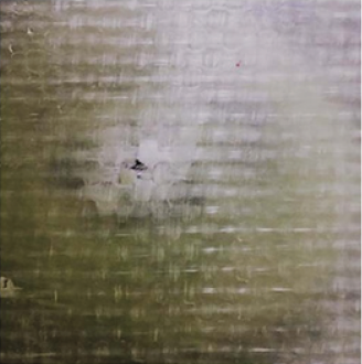
Based upon the speed and the weight of the projectile, the total kinetic energy at the instant of impact is calculated to be 577.6 Joule. As shown in Figure 2, a small hole on the surface of the composite depicts the entering point of the impacted projectile. All three shots were stopped within the panel.
Point bending test
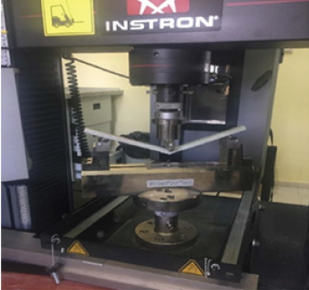
Following the ballistic shots, 3-Point bending test was carried out using 40x10 x11mm test pieces (cut from both x- and y-directions) by Instron 5982 Static Push Pull Instrument (Figure 3).
Figure 3: 1HNMR spectrum of 4,7-dibromo-2,1,3-benzothiadiazole.
Optical microscopy
Cross sections of the damaged composite specimen were inspected first using optical microscopy at magnification x100 and x 500 to evaluate the projectile-material interactions.
Computed tomography (CT)
Detailed damage mechanism of the impacted projectile was investigated using computed tomography (CT) techniques. Computed tomography devices are the most important which provide a better damage view for materials especially for the laminated composite structures. A computed tomography (CT) device has a stationary frame and a rotor, carrying an X-ray source and a radiation detector, which is rotatably mounted at the frame. A number of marks are provided at the rotor at known angular intervals, these marks being scanned by a sensor, which is attached at the frame and which emits an output signal given the passing of a mark. The number of marks is significantly lower than the number of projections that are picked up in each rotation of the rotor. A computing unit determines the projection angles pertaining to the individual projections by interpolation from the output signals of the sensor. As the CT instrument, the NIKON XT H 225 system was used to evaluate the penetration and damage mechanisms of the composite and the penetrated projectile (Figure 4).
Figure 4: The NIKON XT H 225 CT system and the damaged sample.

Results and Discussion
Following a carefully designed processing route to produce composite panels, a void and pore free microstructure is obtained and illustrated in Figure 1. Panels were shot by a 9mm hand gun in an accredited polligon. Two samples extracted from these laminated, pressed and fully cured composite panels (cut from both x- and y-directions) were used in 3-point bending test and the resultant flexural stress vs. extension diagrams are shown below in Figure 5. The maximum flexural stresses were found to be 254.1MPa and 191.9MPa. Maximum flexural strains were found to be 0.060 and 0.021mm/mm respectively.
Figure 5: 3-Point bending test results for the composite samples.

The difference in both max flexural strength and max flexural strain is due to the difference in cutting directions of the samples along with the effect of the damage inserted by the ballistic shots. It should be underlined that 6% flexural strain is noteworthy for such a structure. The panel which was shot by 9mm round nose (RN) bullet was cut to extract the cross sectional zone revealing the damaged regions and penetrated and crushed bullet fragments as shown in Figure 6 & 7. It was measured that the penetration into the material is only 3mm through 11mm thick laminated structure meaning that only a partial penetration (app. 27%) has occurred. Fragments of the copper-brass jacket of the projectile were caught in between the laminates indicating full energy absorption due to strong, stiff and void free composite structure.
Optical microscopy observation on the damaged zone reveals the damage mechanisms such as fiber breakage, matrix cracking and delamination along with the fragmented projectile pieces spreaded through the delaminated interfaces (Figure 6 & 7).
Figure 6: Cross sectional view of the damaged composite panel which was hit by a 9mm projectile. Micrograph below shows an enlarged view of the damaged zone.
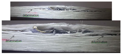
Figure 7: The damaged zone of the laminated composite structure.
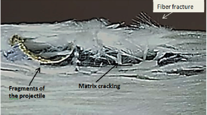
Reported simulation results reveal matrix cracking as the first damage occurs at the bottom of the laminate and delamination follows due to propagation of the matrix crack through the interfaces. Eventually, the fiber failure/fracture occurs at the end of the whole damaging process [11,12]. As illustrated in Figure 6, such mechanism can be observed to occur following the crush of the incoming projectile and delamination seems to start instantaneously in both transverse directions and propagates. Such damaging mechanism can be seen in the Figure 8 indicating the CT scan of the defects and residues of metallic pieces of the projectile were accumulated at the bottom of the laminate due to resisting ductile matrix phase. Enhanced reinforcement of the fibers into matrix provided enough force to resist the penetration of the bullet into the surface along with the strain by the ductile matrix and fibers. Such resistance led the fracture of the copper-brass jacket of the bullet as seen in photomicrographs.
It should be noted that very slight bending of the laminates is observed following the complete stop of the incoming low velocity impact of the projectile. Perforation of the composite structure is initiated as a local failure of the fibers at the impact zone due to micro-cracking of the ductile matrix phase. Major portion of the total kinetic energy is absorbed at the interface and the fiber-matrix junctions. Since the low velocity impact of the bullet is well below the ballistic limit only a partial penetration has occurred and the kinetic energy is fully absorbed following some local fiber fractures.
Computed Tomography scans were applied to the same specimen for precise visualization of the damaged zone and the fragmented projectile (Figure 8-11). Figure 9 illustrates a general view of the CT scan of the damaged surface where a slight swelling on the surface can be seen. Accumulated bumps on the surface reveal those fractured fibers as also shown in Figure 7.
Figure 8: 3-D Transparency view of the fragmented projectile in the damaged zone.
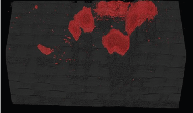
Figure 9: 3-D View of the computed tomography scan of the damaged zone
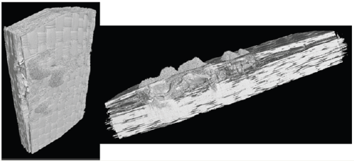
Figure 10: Defect detection by CT scan in the damaged zone.

Figure 11a: CT scan of the damaged zone; 11b: Radiographic view of the fragmented projectile.

CT scan photomicrographs illustrate that the incoming bullet is fully crushed into pieces due to strong resistance of the composite structure. A good processing of the hand lay-up and compression under the press seem to enhance the interfacial strength and fibermatrix reinforcement is quite effective to absorb the kinetic energy of the incoming projectile. Residues of the remaining fragments of the copper-brass jacket of the bullet also indicate the lead core was melted away through the delaminated interfaces. Friction between the incoming bullet and the composite structure probably gave rise to heat enough for melting the lead core of the projectile as the final step of the damaging process.
Figure 11a & 11b show the distribution of these copper-brass sheath fragments in the delaminated interfaces. Metallic pieces are spreaded in transverse direction and causing further propagation of the delamination process. At this point, it should be noted that computed tomography (CT) is such a powerful technique that it visualize the full extent of the damage progression in 3-D. It also reveals the distribution of the remnants of the fragmented bullet through the interfaces of the composite laminates.
Conclusion
Instant microcracking of the matrix phase along with the breakage of the fibers seems to be the major energy absorption mechanism for the low velocity impacts on a composite structure. Majority of the kinetic energy is absorbed at the interface and the ductile fiber-matrix junctions with enhanced strength due to a good processing route (i.e. application of careful lay-up process and compression under the press). Frictional forces in between the incoming bullet and the composite interface lead to instant heat to melt away the lead core of the bullet through the delaminated interfaces. Computed tomography (CT) is such a powerful technique that it visualizes the full extent of the damage progression in 3-D. For low velocity impacts, such a technique can be used for the visualization of the full damaged zone from the initial impact point to the final end of the fragmented bullet.
Acknowledgment
a. Authors thank to the Istanbul Development Agency for their support.
b. Authors also thank to Karfo Industrial Company for their support to use The NIKON XT H 225 CT system.
References
- Chocron B, Rodriguez J, V. Sánchez Gálvez (1997) A simple analytical model for ballistic impact in composites. J Phys IV France 7(C3): C3- 821-C3-826.
- (2007) Finite element simulations of ballistic impact on metal and composite plates, Sai Kiran Chelluru (Ed.), Wichita State University, USA.
- Dimko D, Vineta S, Natasa M (2015) Ballistic impact resistance mechanism of woven fabrics and their composites. IJERT 4(12): 107- 111.
- Reddy PRS, Reddy TS, Madhu V, Gogia AK, Rao KV (2015) Behavior of E-glass composite laminates under ballistic impact. Materials and Design 84: 79-86.
- Akella K, Naik NK (2015) Composite Armour-A Review. Journal of the Indian Institute of Science 95(3).
- O’Masta MR, Crayton DH, Deshpande VS, Wadley HNG (2015) Mechanisms of penetration in polyethylene reinforced cross-ply laminates. International Journal of Impact Engineering 86: 249-264.
- Shaktivesh, Nair NS, Ch Sesha KV, Naik NK (2013) Ballistic impact performance of composite targets. Materials and Design 51: 833-846.
- Bandaru AK, Ahmad S (2016) Modeling of progressive damage for composites under ballistic impact. Composites Part B 93: 75-87.
- Gama BA, Gillespie JW (2011) Finite element modeling of impact, damage evolution and penetration of thick-section composites. International Journal of Impact Engineering 38: 181-197.
- Hogg PJ (2003) Composites for Ballistic Applications, Queen Mary, University of London, UK.
- Lei Yang, Zhanjun W, Dongyue G, Xin L (2016) Microscopic damage mechanisms of fibre reinforced composite laminates subjected to low velocity impact. Computational Materials Science 111: 148-156.
- Naik NK, Shrirao P (2004) Composite structures under ballistic impact. Composite Structures 66: 579-590.
© 2017 Emre Yılmaz, et al. This is an open access article distributed under the terms of the Creative Commons Attribution License , which permits unrestricted use, distribution, and build upon your work non-commercially.
 a Creative Commons Attribution 4.0 International License. Based on a work at www.crimsonpublishers.com.
Best viewed in


.jpg)


 Editorial Board Registrations
 Submit your Article
 Refer a Friend
 Advertise With Us
.jpg)


.jpg)


.bmp)
.jpg)
.png)
.jpg)


.jpg)


.png)

.png)


.png)


