- Submissions

Full Text
Academic Journal of Engineering Studies
Laboratory Studies on the Application of Convergence Measuring Device for Monitoring Borehole Deformation
Jun Hyuk Heo1*, Noune Melkoumian1 and Sam Saeed Hashemi2
1Department of Civil, Environmental and Mining Engineering, University of Adelaide, Australia
2Department of Energy Resources Engineering, Stanford University, United States
*Corresponding author: Jun Hyuk Heo, Department of Civil, Environmental and Mining Engineering, University of Adelaide, Australia
Submission: July 30, 2022; Published: August 11, 2022
.jpg)
ISSN:2694-4421 Volume3 Issue1
Abstract
Borehole convergence or the change in borehole diameter during or after drilling is one of the primary indicators of borehole instability. Early recognition of borehole instability is critical in achieving successful and timely completion of drilling operations and for borehole exploitation. Commonly used borehole monitoring devices, such as the caliper log and the acoustic borehole televiewer, provide continuous measurement of the borehole diameter when drilling into subsurface formations. However, limited attempts have been made to accurately measure the borehole diameter changes in laboratoryscale studies. In this study, series of laboratory experiments were conducted on Thick-Walled Hollow Cylinder (TWHC) specimens made of synthetic poorly cemented sandstone, where a new laboratory-scale Convergence Measuring Device (CMD) was deployed inside the borehole for monitoring the deformation of the borehole walls. This new CMD was developed based on the concept of Local Deformation Transducer (LDT). Three different cement contents (i.e., 10%, 12%, and 14%) and various lateral confining stress conditions (i.e., 2 MPa, 4 MPa and 6 MPa) were considered to evaluate the performance of the CMD. The specimens with CMD were tested using a modified Hoek cell which enabled visual monitoring of the borehole convergence and borehole wall breakout processes during the tests. The results showed that the CMD was capable of accurately measuring the borehole deformation. Visual monitoring of the borehole allowed precise identification of the locations and shapes of the borehole wall breakouts. Studies showed that the amount of the cement content and the magnitude of the lateral confining stress have a significant effect on the borehole deformation and failure stress. Furthermore, it was observed that the rate of increase in the radial strain of the TWHC specimens prior to the initiation of a borehole wall failure decreases when the cement content was increased.
Keywords:Borehole deformation; Borehole monitoring; Convergence measuring device; Thick-walled hollow cylinder; Laboratory study; Poorly cemented sandstone
Introduction
Drilling exploration boreholes into the ground are one of the most widely used methods for investigating the subsurface formations in energy and mineral resources industry. As with any other excavation, drilling a borehole disturbs local pre-existing stresses in the vicinity of the opening, and this may result in rock failure due to the induced local stresses exceeding the rock strength. In practice, borehole instabilities may occur seemingly unpredictably at any stage of the drilling operations, resulting in the loss of time and equipment, as well as, in extreme cases, in abandoning the borehole [1]. It has been estimated that about 70% of the world’s hydrocarbon reservoirs are found within poorly cemented formations, where borehole instabilities are most likely to occur [2]. Furthermore, a significant number of exploration boreholes being drilled through poorly cemented formations worldwide, and particularly in Australia, often result in technical difficulties such as stuck pipes [3]. Borehole instability problems typically account for 5-10% of the total drilling costs and add up to the annual cost of hundreds of millions of dollars worldwide [4]. Therefore, predicting the poorly cemented rock behavior in the vicinity of excavation is essential for maintaining its stability and, consequently, for reducing the drilling costs. Most of the research conducted on borehole instability focuses on the initial stability of a circular borehole by comparing the borehole stress with the in-situ rock strength [5]. This approach fails to account for the progressive borehole failure. During drilling stages, the stress conditions around a borehole can change significantly, and poorly cemented formations are especially vulnerable to such alterations in stress conditions due to their weak nature. Therefore, it is important to gain a comprehensive understanding of the borehole failure mechanisms, including the effect of the borehole convergence on the borehole stability under various stress conditions. This study introduces a new laboratoryscale Convergence Measuring Device (CMD) that has been developed for continuous real-time monitoring of the borehole deformation in TWHC specimens during the laboratory tests. Test results show, that the proposed CMD is an ideal tool for such applications. Unlike the commercially available CMDs such as the convergence meter, convergence monitor and borehole extensometer, which size and shape are designed for field applications primarily [6], the proposed CMD is free from these limitations since it has been specifically designed for laboratory applications. In this work, laboratory studies on the stability of a borehole drilled through weak poorly cemented sandstone were conducted through series of TWHC tests, where, in combination with the real-time visual monitoring of the borehole failure, newly developed CMD has been applied to accurately measure the changes in the borehole diameter.
CMD Background
Predicting and managing formation deformation in the vicinity of underground openings is an important aspect in the design and assessment of the performance of various geotechnical structures, such as tunnels, deep excavations, wellbores, and boreholes. Although some field studies can be conducted on this, most comprehensive studies are laboratory-based and use smallscale models, such as TWHC specimens for laboratory testing. The accurate measurement of the borehole convergence in these TWHC specimens has been one of the challenging topics of geomechanics in recent decades. Hight [7] developed a hollow cylinder apparatus for investigating the effects of principal stress rotation in soils. Tronvoll [8] employed a clip gage for measuring the borehole convergence in TWHC tests. Rawlings et al. [9] used a diameter caliper to measure the change in the borehole diameter of TWHC specimens by measuring it before and after the triaxial tests. O’Kelly and Naughton [10] used proximity transducers that measure the radial displacements in the hollow cylindrical specimens. Papamichos et al. [11] measured the borehole strain using an internal radial cantilever. Bujok et al. [12] studied the convergence of the abandoned shallow oil wells through experimental modeling focused on the effects of borehole convergence on its deformation shape. Wu et al. [5] used a borehole gage to measure the change in the borehole diameter during the borehole stability experiment. Recently, Trezeciak et al. [13] conducted laboratory evaluation to monitor borehole initiation using acoustic emission sensors. These studies focused primarily on the convergence measurement without the real-time visual monitoring of the borehole during testing. In this work, a new application of the Local Deformation Transducer (LDT) has been considered and used for the development of the proposed CMD, with the aim of allowing accurate measurement of the borehole convergence under various stress conditions. The basic principle of the suggested CMD is like that of the LDT which was originally proposed by Goto et al. [14] to minimize the error present in the axial strain measurements from the triaxial testing. In designing and manufacturing the CMD, strain gages have been used. This is a common practice in designing transducers that convert a mechanical change, such as displacement, into a change in the voltage signal that is monitored after calibrating.
Experimental Study
Laboratory facilities
The Uniaxial Compressive Strength (UCS), triaxial and TWHC tests are the most used laboratory experiments for determining the parameters required for borehole stability analysis and understanding the behavior of a granular formation under different stress conditions. In this study, the borehole stability experiments were performed on TWHC specimens in a modified Hoek Cell. The TWHC specimens had an external diameter of 63.5mm, the internal diameter of 15mm, and a height of 127mm. During each test, the TWHC specimen was subjected to axial stress along the borehole axis, and the confining stress was provided by a servo-controlled hydraulic device. Several laboratory facilities were used for conducting the tests. For applying vertical stress to the specimen, a servo controlled axial loading system of 300kN capacity with 0.1N accuracy was used. For applying and maintaining the external confining pressure at a very low level, the Hoek cell connected to an automatic hydraulic machine, which had a relief valve and a pressure gage with an accuracy of 0.01 MPa, was used. CMDs were placed inside the borehole of the TWHC specimen for measuring the borehole convergence, and a micro camera with the resolution of 225 Pixels Per Inch (PPI) was placed inside the hollow platen of the Hoek cell for recording the borehole wall deformation during the testing and for its real-time visual monitoring. A 60-channel data acquisition system was connected to computers to monitor and record the axial force, axial displacement, axial strain, lateral strain, convergence measurement and time into a storage device.
Cut-off UCS
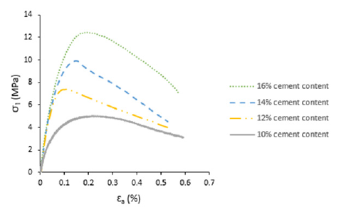
Poorly cemented sandstones are characterized by low strength, poor cementation, and high porosity [15]. The UCS test results are generally considered for classification of weak sandstones from stronger hard rocks [16, 17]. In this study, Baud and Gambin [18] approach for selecting the soft rocks based on the UCS upper limit of 10 MPa, as well as Liu and Wu [5] guidance on classifying weak sandstone from stronger sandstone based on the UCS have been taken into consideration. To identify the mechanical properties a series of UCS tests were conducted on synthetic sandstones with various cement contents while keeping the water and sand components constant. Synthetic sandstone samples with four different cement contents, namely 10%,12%, 14% and 16% were considered for studying the effect of cement content on the UCS. These UCS tests were conducted based on the ISRM suggested methods [16] and under the same testing conditions. Figure 1(a-c) illustrate the compactor used to achieve uniform compaction of the specimen mixture in the mold, the synthetic rock specimens cast in the metal molds, and the final solid synthetic specimens prepared for UCS testing respectively. The specimens were tested after 8 days of curing time and the average dry density was measured to be 1.79g/cm³. The stress-strain diagrams obtained from the UCS tests are presented in Figure 2, the maximum strength, σmax and the pre-maximum stiffness increase as the cement content increases. This trend agrees with the UCS test results obtained by [19] who used a lower range of cement content between 5% and 8%. It was observed that an increase in the cement content resulted in a higher maximum strength which also matches closely with other studies conducted on the influence of cement content on the UCS of synthetic sandstone specimens [20,21]. As can be seen from Figure 2, the solid specimens with higher than 14% cement content exceeded the UCS of 10 MPa, therefore, 14% was identified as the upper cut-off cement content for this study, as increasing the cement content beyond this level resulted in a stronger specimen which does not meet the strength characteristic of a poorly cemented rock [22]. Three cementation levels (i.e., 10%, 12% and 14%) were considered for TWHC experiments.
Figure 1: (a) Compactor, (b) Samples in the molds, (c) Unmolded samples.

Figure 2: Stress versus axial strain behavior for specimens subjected to UCS testing.
Sample preparation and properties
The sampling and preparation of natural poorly cemented sandstones for testing are usually very problematic due to difficulty in collecting undisturbed samples. As a result, sophisticated methods have been proposed by various researchers to make realistic synthetic poorly cemented sandstone samples for testing [21,23]. Synthetic rock specimens are commonly used as an alternative for natural rocks for conducting laboratory-based borehole stability experiments [3]. The preparation of synthetic rocks involves mixing sand grains, a cementing agent and water. The mechanical properties of the prepared synthetic rock specimens depend on the individual components used in the mixture. A small variation in the initial components has a significant influence on the mechanical properties of the final specimens. This indicates the importance of the careful selection of the components for the mixture. It has been observed that the mechanical properties of the synthetic rocks are primarily controlled by the cementation as grains are bonded together with a cementing agent [21]. Galvan and Kanji [24] tested synthetic rock samples made under controlled conditions and found that the mechanical properties of the synthetic samples closely resembled those of the natural rocks.
To prepare synthetic sandstone samples with reasonably homogeneous properties, it is important to establish and follow a consistent sample preparation procedure. The synthetic sandstone specimens used in this study were prepared according to the mixture preparation procedure for a poorly cemented formation proposed by Hashemi et al. [3]. The mixture was composed of natural silica sands with two different grain size ranges, namely, coarse grain sands with a grain size between 0.425mm-1.4mm, and fine grain sands with a grain size between 0.15mm-0.355mm, Portland cement type II (specific gravity, GS=3.15g/cm³) and water. The components were thoroughly mixed to achieve a homogeneous mixture for specimens, and the time spent between pouring water into the dry mixture and compacting it into metal molds was maintained to be within 30 minutes to avoid initial setting of the cement. Each sample was prepared by compacting the mixture into three equal layers of 42mm thickness. The top surface of the bottom layer was scratched before the subsequent layer was compacted on top of it to ensure thorough interlocking between the successive layers. The mixture was not strong enough to bond sand grains in the early curing stage. Thus, the samples were left in the mold for five days, and then were removed from the mold and cured for another three days wrapped in a plastic film at room temperature (18-23 °C) before testing. Mechanical properties of the specimens are presented in Table 1.
Table 1:Mechanical properties of the synthetic specimens.

Design of the CMD
Figure 3: An illustration of components in a CMD 1. Metal frame, 2. Strain gage, 3. Plastic beads.
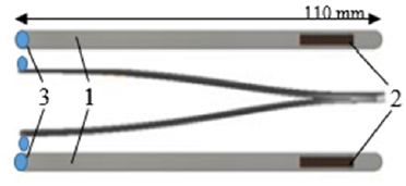
The Convergence Measuring Device (CMD) is a simple mechanical device consisting of two strain gages attached to a V-shaped metal frame and positioned right opposite each other as is shown in Figure 3. Each strain gage is placed near the closed end of the metal frame where they exhibit the strain in compression or tension when the open ends of the CMD legs move. To allow a smooth contact with the borehole wall, round plastic bead is attached to each side of the outer surface of the CMD legs using a strong glue. The CMD was designed and developed with the primary focus on the contact-based method, as the main purpose of the CMD is achieving an accurate measurement of the borehole deformation in the TWHC specimens subjected to triaxial testing under various stress conditions. Non-contact-based methods, such as the laser strain measurement device, were not considered due to the limited space inside a TWHC specimen not allowing to place such devices. The CMD is manufactured to be compact enough to be deployed inside a TWHC specimen with a small borehole size of 15mm. The shape of the CMD was designed to allow for it be freely moved in and out of the borehole, and the dimensions of the metal frame were selected based on the size of the TWHC specimens to be tested. The key advantages of the proposed CMD are in its relatively simple manufacturing process, and in the versatility of its size, i.e., it can be manufactured in any size required to fit the specimen under consideration.
The working principle of the CMD is such that, when the borehole of the TWHC specimen is deformed under triaxial stress conditions, the movement of the CMD legs triggers either increase or decrease in the gage strain depending on the applied stress paths. The measurements taken from the two strain gages are then averaged and converted to displacement measurement through a calibration process: by co-relating the CMD leg displacement and the output from the strain gages. The strain gage currently in use has a resistance of 120 ohms with a grid dimension of 2.5mm wide and 10mm long (TML FLA-10-11). The two strain gages form a half Wheatstone bridge to enhance measurement accuracy and minimize the temperature effect.
Calibration of the CMD
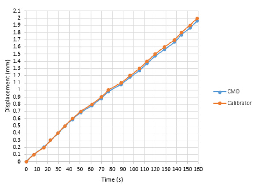
The calibration of the CMD was carried out by comparing and modifying the electrical value output from the strain gage versus the displacement output from the digital calibrator. The initial distance between the open ends of the CMD was set at 15mm which matches the borehole diameter of the TWHC specimens. Both the CMD and the digital calibrator readings were zeroed for the initial measurement and then subsequent measurements were taken at every 0.1mm displacement as the distance between the CMD legs was contracted by 0.1mm at a step to its full range capacity. A digital micrometer (Mitutoyo digimatic micrometer 164), as shown in Figure 4, with a resolution of 0.01mm was used to get reference measurements for the calibration of the CMD. The calibration was carried out by comparing the measurements from the CMD and the digital micrometer output versus time. Figure 5 presents the calibrated CMD output where the displacement matches closely with the calibrator output. Furthermore, to investigate the influence of the surface roughness on CMD reading several sensitivity tests were conducted on different types of surface materials in addition to the synthetic rocks. The results showed a consistent CMD reading for different types of surface materials.
Figure 4: Digital micrometer and calibration set-up.
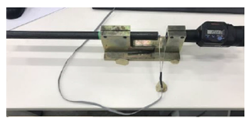
Figure 5: The CMD output from the calibration tests.
Experiment setup and procedure
A modified Hoek cell designed and manufactured by Hashemi and Melkoumian [19] consisting of two sets of cylindrical platens was used for conducting the TWHC tests. A micro camera was fitted inside the test cell to monitor and record the borehole wall in realtime. The Hoek cell was synchronized with a pressure maintainer specifically tuned for applying a low confining pressure without leakage. The CMDs were placed inside the TWHC specimen as shown in Figure 6(a). A hollow cylindrical metal spacer made from hardened steel matching the diameter of the TWHC specimen was placed in between the specimen and the hollow platen to maintain the CMD in the vertical position during testing. A total of two CMDs were used for each test to improve the accuracy of the convergence measurement. The top CMD was placed alongside the camera and approximately 42mm from the top end surface of the specimen, and the bottom CMD was placed on the direct opposite location of the top CMD.
The end surfaces of each specimen were prepared to be flat and parallel to each other by applying a thin layer of dental paste. Lubrication was applied on the end surfaces to minimize the friction between the platen and the specimen. Furthermore, spherical platens were placed on top of the hollow platen to ensure that uniform vertical stress is applied onto the TWHC specimen during testing and to minimize the bedding error. A pair of axial and lateral strain gages were attached directly to the sample surface to measure local deformations. A small load of approximately 5N was applied by the loading machine as the top ram was lowered down to the surface of the platen prior to the commencement of the test to ensure full contact between the top ram and the platen. The image captured by the micro camera as shown in Figure 6(b) was checked for the clear focal point of the camera and to ensure that the CMDs were positioned vertically. The experiments were performed in two loading stages. In the first stage, simultaneous vertical and confining stresses were applied up to a pre-defined stress level to simulate the hydrostatic stress condition in the first stage of loading; and the second stage followed by increasing the vertical load at a constant displacement rate of 0.07mm/min. The confining pressure was varied in each test to apply the desired confining stress to the TWHC specimen.
Figure 6:(a) The CMDs placed inside the Hoek cell and (b) the view from the micro camera.

Result and Discussion
UCS test results on solid specimens
The UCS test results showed that the maximum strength and the pre-maximum stiffness increase as the cement content was increased. The influence of cement content on the peak strength was substantial. The UCS increased by 48% when the cement content was increased from 10% to 12%. Further increases in the cement content to 14% and 16% resulted in 35% and 25% increase in the UCS respectively, indicating that the influence of the cement content on the maximum strength becomes less significant as the cement content increases. This can be caused by the reduction in the grain-to-grain space available for cementation due to the increased cement content which pushes grains closer. Furthermore, according to Chen and Wu [25], low water to cement ratio results in decreased cement hydration. Thus, the increase in the cement content for the same water content could also have contributed to the reduced cement hydration due to excess cement particles not reacting with water. Laboratory studies by Saidi et al. [21] also observed that in granular materials adding an additional cementing agent to the specimens with a low cement content of less than 20% is more likely to significantly increase their maximum strength, than adding a more cementing agent to the specimens with a higher cement content. The post-peak stress-strain trend of samples with 10% cement content showed a greater ductile behavior compared to the samples with a higher cement content of 12% and 14%. Moreover, the effect of water content was studied by varying the amount of water content between 10% and 12% while keeping other components unchanged. The increase in the water content resulted in strength reduction because of the increased total porosity. This outcome agrees with previous studies by Hashemi et al. [3] conducted on synthetic sandstones with 10% water content.
Triaxial test results on solid specimens
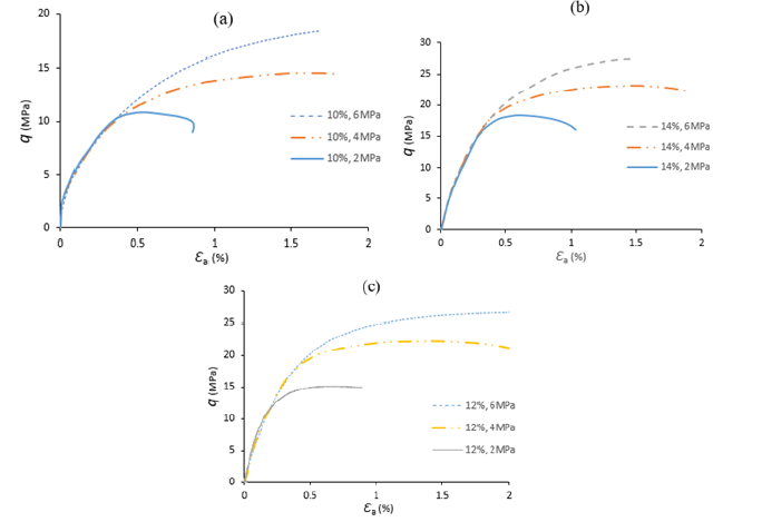
Triaxial tests were carried out on solid cylindrical specimens with three different cement contents based on the preliminary UCS test results. Specimens with cement contents of 10%, 12%, and 14% were tested under different stress conditions. Figure 7(a-c) present the deviatoric stress (σdeviatoric=σ1-σhydrostatic) versus the axial strain diagram for solid specimens with different cement contents. According to the results, an increase in the cement content and confining pressure resulted in the increase in the peak strength and the stiffness of the specimens as seen from the UCS tests. The specimens showed strain hardening behavior and the material behaved non-linearly in the early stage of the loading processes. The non-linearity could be due to the rearrangement of sand particles leading to the closure of microcracks as the stress level was increased. Khan [26] also observed such nonlinear behavior in triaxial compression experiments using weak Berea sandstone. Hashemi et al. [3] showed that the peak strength and ductility increase with the increase in the confining pressure. As shown in Figure 7(a-c), increasing the confining pressure results in the transition from the brittle to ductile behavior. The ductility of specimens at a lower confining pressure of 2 MPa is less significant than at higher confining pressures of 4 MPa and 6 MPa.
Figure 7:Deviatoric stress versus axial strain behaviour of solid specimens subjected to triaxial testing, (a) 10 % cement content, (b) 12 % cement content, (c) 14 % cement content.
Triaxial tests on thick-walled hollow cylinder specimens
Figure 8:Deviatoric stress versus axial strain for TWHC specimens: (a) 10% cement content, (b) 12% cement content, (c) 14% cement content.
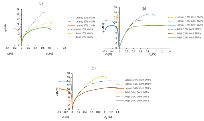
Triaxial tests were conducted on TWHC specimens with 15mm diameter borehole for three different cement contents (10%, 12% and 14%) and various confining pressures. As shown in Figure 8(ac), increasing the confining pressure by 2 MPa, increases the level of the peak strength and strain by up to 20%. The pre-peak stiffness does not change dramatically with an increase in the confining pressure. However, for greater than 4 MPa of confining pressure, the increment in the level of strength is lower than that for the previous confining pressure of 2 MPa [27]. For higher than 6 MPa of confining pressures the borehole collapsed prior to reaching the hydrostatic stress and, consequently, the strain gages on the specimens failed due to the weak surface of the specimen. Also, increasing the cement content while keeping the other parameters unchanged for sample preparation and test condition, increased the stiffness of the specimens [28]
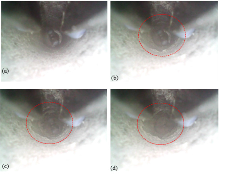
In the TWHC tests, a micro camera was used for real-time monitoring of the borehole. Visual monitoring of the borehole enabled identifying the location and shape of the borehole breakout areas. Figure 9(a-d) show the process of the borehole breakout captured by the camera during the axial loading test on a THWC specimen with 14% cement content under 4 MPa of confining pressure. The borehole breakout took place in the form of a concentrated shear band around the borehole perimeter near the midpoint of the TWHC specimen as highlighted by the red circle [29]. This result agrees with Papamichos’ [11] findings, who observed toroidally shaped shear band forming around the borehole during axial loading in a hollow cylinder test. The change in the borehole diameter was calculated by averaging the measurements taken by the two CMDs. The average borehole diameter measured by the CMDs at three different stages during the process of borehole breakout were 0.28mm for Figure 9(b), 0.52mm for Figure 9(c) and 0.97mm for Figure 9(d). The test results obtained from the CMDs during the TWHC tests for three different cement contents at various confining pressures are shown in Figure 10(a-c). The specimens were loaded until borehole failure was observed from the video camera placed inside the borehole of the TWHC specimen. The deviatoric stress is plotted versus the borehole radial strain measured by the CMDs.
Figure 9:Borehole breakout captured by the micro camera.
The stress-strain response of the TWHC specimen with 10% cement content in Figure 10(a) shows a constant increase in the radial strain as the borehole diameter converged gradually due to axial loading. The radial strain was initially 0%, but with the increasing stress, the radial strain increased. This is due to the compressive stress, which leads to material plastification, borehole convergence and eventually borehole failure. The radial strain of the borehole increased at a faster rate once the borehole convergence was initiated. An increase in the confining pressure from 2 MPa to 6 MPa had a minimal effect on the change in the radial strain rate. A higher peak strength was observed for specimens tested under a higher confining pressure of 6 MPa compared to the specimens tested at lower confining pressures. This agrees with the experimental observations by Papamichos et al. [11].
Figure 10(b-c) present the results from the specimen with a higher cement content of 12% and 14% respectively. The stressstrain behavior of the TWHC specimens tested under 6 MPa was like that for the specimens with a lower cement content of 10%. A different behavior was observed for the specimens with 10% and 12% cement contents tested under a confining pressure of 4 MPa, as can be seen in Figure 10(b). The radial strain decreased prior to the initiation of the borehole failure, and this is due to the higher level of axial stress resulting in the expansion of the borehole at the contact point with the CMD devices. Prior to the initiation of the borehole break out, the radial strain increased as a relatively linear function of the deviatoric stress, as can be seen in Figure 10(b-c). A constant increase in the radial strain was observed once the borehole breakout initiated.
Figure 10:Deviatoric stress versus radial strain behavior measured by the CMD for TWHC specimens subjected to triaxial testing: (a) 10% cement content, (b) 12% cement content, (c) 14% cement content.
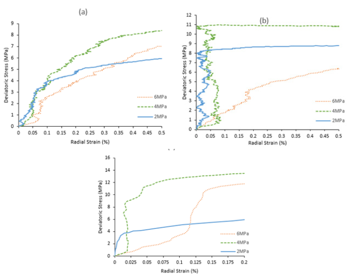
The radial strain of the specimens with a higher cement content of 12% and 14% tested under various lateral confining pressures changed less significantly prior to the initiation of the borehole failure compared to the specimens with a lower cement content of 10%. As shown in Figure 10(a), the radial strain of the specimens with 10% cement content increases at a relatively steady rate up to 0.1%. After this point, the radial strain increases at a faster rate, indicating that the borehole diameter began to converge. However, Figure 10(b-c) show that the radial strain of the specimens with 12% and 14% cement contents tested under 2 MPa and 4 MPa of confining pressures changed less significantly prior to the rapid increase in the radial strain being observed once a specific radial strain was reached, indicating the collapse of the borehole wall when a critical deviatoric stress was applied. The specimens tested under a higher confining pressure of 6 MPa demonstrated a more gradual borehole convergence process as indicated by the constant increase in the radial strain compared to the specimens tested at a lower confining pressure. The results also showed that the increase in the cement content significantly influenced the deviatoric stress required to initiate the borehole convergence. However, the increment in the level of the deviatoric stress required for the borehole convergence initiation decreased when a high confining pressure of 6 MPa was applied.
Conclusion
A new laboratory-scale convergence measuring device was developed and applied in a series of laboratory experiments to measure the borehole deformation in TWHC specimens of synthetic poorly cemented sandstones with different amounts of cement contents. By using the CMDs, it was possible to accurately measure the borehole deformation in the TWHC specimens. The results showed that the cement content and the magnitude of the lateral confining stress affect the borehole deformation behavior and the failure stress. In UCS tests, the maximum strength and premax stiffness increased with the increase in the cement content. However, the magnitude of increase in the maximum strength reduced as the cement content increased. The specimens with a lower cement content of 10% showed a greater ductility than the specimens with a higher cement content. Triaxial test results showed a strain hardening behavior with the increase in the cement content. The increase in the confining pressure resulted in the transition from a brittle to ductile behavior. The peak strength and strain were largely influenced by the amount of the cement content. Also, it was observed that the increment in the level of the peak strength reduced as the confining pressure increased.
Visual monitoring of the borehole allowed identifying the location and shape of the borehole breakout areas. The failure shape observed for the axial loading test was in the form of a shear band around the borehole wall, and the damage development and its localization into a shear band was successfully captured by the video camera placed inside the borehole of the TWHC. The effect of the borehole deformation was investigated using the CMDs. The results showed that a relatively linear function of the deviatoric stress followed by a constant increase in the radial strain was observed as the borehole failure initiated. Prior to the initiation of the borehole failure, the radial strain of the specimens with a higher amount of cement content increased less dramatically compared to that for the specimens with a 10% cement content, indicating that the load-bearing capacity increases when the cement content is increased.
In summary, the presented experimental studies using the proposed CMDs have helped to gain a better understanding of the effects of the cement content and confining pressure on the borehole deformation behavior and failure stress. Based on this finding, new drilling strategies could be developed in the mining and petroleum industries to minimize borehole failures in poorly cemented sandy formations.
References
- Fjar E, Holt R, Raaen A, Risnes R, Horsrud P (2008) Petroleum related rock mechanics. (2nd edn), Netherlands, pp.309-310.
- Bianco PM, Halleck (2001) Mechanisms of arch instability and sand production in two-phase saturated poorly consolidated sandstones. Netherlands.
- Hashemi SS, Melkoumian N, Taheri A, Jaksa M (2015) The failure behavior of poorly cemented sands at a borehole wall using laboratory tests. International Journal of Rock Mechanics and Mining Sciences, 77: 348-357.
- Al Ajmi A, Zimmerman R (2006) Stability analysis of vertical boreholes using the Mogi Coulomb failure criterion. International Journal of Rock Mechanics and Mining Sciences 43(8): 1200-1211.
- Liu K, Wu B (2016) Predicting reservoir rock mechanical properties directly from sedimentary characterisation. Australia.
- Li SJ, Feng XT, Hudson JA (2012) ISRM suggested method for measuring rock mass displacement using a sliding micrometer. Rock Mechanics and Rock Engineering 46(3): 645-653.
- Hight D, Gens A, Symes M (1983) The development of a new hollow cylinder apparatus for investigating the effects of principal stress rotation in soils. Géotechnique, 33(4): 355-383.
- Tronvoll J (1991) Experimental investigation of perforation cavity stability. International Journal of Rock Mechanics and Mining Sciences & Geomechanics Abstracts 30(2): 365-373.
- Rawlings C, Barton N, Bandis S, Addis M, Gutierrez M (1993) Laboratory and numerical discontinue modeling of wellbore stability. Journal of Petroleum Technology 45(11): 1086-1092.
- O Kelly BC, Naughton PJ (2008) Use of proximity transducers for local radial strain measurements in a hollow cylinder apparatus. USA, pp. 1-8.
- Papamichos E, Tronvoll J, Skjaerstein A, Unander TE (2010) Hole stability of red wildmoor sandstone under anisotropic stresses and sand production criterion. J Pet Sci Eng 72(1-2): 78-92.
- Bujok P, Porzer M, Labus K, Klempa M, Pavluš J (2013) Experimental modeling of abandoned shallow oil wells convergence. Engineering Geology 157:1-7.
- Trzeciak M, Sone H, Voegeli S, Bate C, Wang H (2021) Laboratory evaluation of the thermal breakout method for maximum horizontal stress measurement. Rock Mechanics and Rock Engineering, 55(1): 51-69.
- Goto S, Tatsuoka F, Shibuya S, Kim Y, Sato T (1991) A simple gauge for local small strain measurements in the laboratory. Soils and Foundations 31(1): 169-180.
- Bosio JJ, Kanji MA (1998) Soft rocks of the Rio de la Plata basin. In: AA Balkema (Ed.), Netherlands, pp. 65e71.
- ISRM (1981) Rock characterization, testing, and monitoring. International Journal of Rock Mechanics and Mining Sciences & Geomechanics Abstracts 18(6): 109.
- Kanji M (2014) Critical issues in soft rocks. Journal of Rock Mechanics and Geotechnical Engineering 6(3): 186-195.
- Baud JP, Gambin M (2011) Classification of soils and rocks based on pressure meter tests under high pressure. Mill Press, Greece, pp. 325e30.
- Hashemi SS, Melkoumian N (2016) Effect of different stress path regimes on borehole instability in poorly cemented granular formations. Journal of Petroleum Science and Engineering 146: 30-49.
- Bernabe Y, Fryer D, Hayes J (1992) The effect of cement on the strength of granular rocks. Geophys Res Lett 19(14): 1511-1514.
- Saidi, F, Bernabe Y, Reuschle T (2003) The mechanical behavior of synthetic, poorly consolidated granular rock under uniaxial compression. Tectonophysics 370(1-2): 105-120.
- Klein (2001) An approach to the classification of weak rock for tunnel projects. California.
- Holt R, Kjølaas J, Larsen I, Li L, Gotusso Pillitteri A, et al. (2005) Comparison between controlled laboratory experiments and discrete particle simulations of the mechanical behavior of rock. International Journal of Rock Mechanics and Mining Sciences 42(7-8): 985-995.
- Galván V, Kanji MA (2011) Simulation of arenaceous weak rocks by means of cemented sands. CRC Press, China, p. 751e2.
- Chen X, Wu S (2013) Influence of water-to-cement ratio and curing period on pore structure of cement mortar. Construction and Building Materials 38: 804-812.
- Khan A, Xiang Y, Huang S (1991) Behavior of Berea sandstone under confining pressure PART I: yield and failure surfaces, and nonlinear elastic response. International Journal of Plasticity 7(6): 607-624.
- Papamichos E, Liolios P, Vanden Hoek PJ (2004) Breakout stability experiments and analysis. In: 6th North America Rock Mechanics Symposium. Houston: American Rock Mechanics Association.
- Wu B, Chen Z, Zhang X (2016) Stability of borehole with breakouts-an experimental and numerical modelling study. In: 50th US Rock Mechanics/Geomechanics Symposium. Houston: American Rock Mechanics Association.
- Zhu X, Liu W (2013) The effects of drill string impacts on wellbore stability. Journal of Petroleum Science and Engineering 109: 217-229.
© 2022 Jun Hyuk Heo. This is an open access article distributed under the terms of the Creative Commons Attribution License , which permits unrestricted use, distribution, and build upon your work non-commercially.
 a Creative Commons Attribution 4.0 International License. Based on a work at www.crimsonpublishers.com.
Best viewed in


.jpg)


 Editorial Board Registrations
 Submit your Article
 Refer a Friend
 Advertise With Us
.jpg)


.jpg)


.bmp)
.jpg)
.png)
.jpg)


.jpg)


.png)

.png)


.png)


