- Submissions

Full Text
Academic Journal of Engineering Studies
Behaviour of Geometrically Nonlinear Columns: Towards an Accurate Structural Design of Columns Made Using Hot Rolled-Open Steel Section
Hussein Mohammed1*, Rawaz Kurda2*, Peshkawt Dolamari3, Babar Ali4, Liaqat Qureshi5, Hisham Hafez6 and Amr Elnemr7
1School of Engineering, University of Edinburgh, UK
2CERIS, Civil Engineering, Architecture and Georresources Department, Instituto Superior Técnico, Universidade de Lisboa, Portugal
3Civil Engineering Department, Hasan Kalyoncu University, Turkey
4COMSATS University Islamabad-Sahiwal Campus, Pakistan
5Department of Civil Engineering, Swedish College of Engineering and Technology, Pakistan
6Department of Mechanical and Construction Engineering, University of Northumbria, UK
7Department of Civil Engineering, German University in Cairo, Egypt
*Corresponding author: Hussein
Mohammed, School of Engineering,
University of Edinburgh, Edinburgh, EH9
3JL, UK
Rawaz Kurda, CERIS, Civil Engineering,
Architecture and Georresources
Department, Instituto Superior Técnico,
Universidade de Lisboa, Av. Rovisco Pais,
1049-001 Lisbon, Portugal
Submission: November 01, 2020 Published: April 15, 2021
.jpg)
ISSN:2694-4421 Volume2 Issue1
Abstract
Geometrically nonlinear columns have been used for a variety of reasons in buildings, and their use has become even more prevalent in our time. Much research has been carried out regarding columns and arches, but geometrically nonlinear columns have not been extensively covered. Thus, this paper sheds a light on the behaviour of nonlinear columns when subjected to loading. For that purpose, two different cases of geometrical nonlinearities were considered. These columns were modelled using a validated Finite Element (FE) model. Each of the columns was loaded up to the buckling load and the displacement was recorded. Length of the column, the included angle (i.e., shallowness or span/reach ratio) and boundary conditions were taken as variables and the behaviour of columns noted each time. Additionally, a brief review of the available guidance from building codes showed a gap when it comes to nonlinear steel columns design. The results of this study showed a similarity between these columns and arches in terms of their behaviour up to the point of buckling. A parametric study was also performed to highlight the sensitivity of this hypothesis to changes in the studied parameters.
Keywords: Buckling; Compression; Flexure; Geometrically Nonlinear Columns; In-plane buckling; Open steel sections; Out of plane buckling
Introduction
Generally, columns transfer applied loads through compression. Other types of stresses
(such as flexural and torsional) also do form in columns, especially columns in use within a
structure rather than those erected in a laboratory setting for testing purposes. The nature
of the stresses developing in columns varies widely depending on several factors such as the
type of building where the column is erected, the type of the column connections (i.e., a simple
column or a fixed-end column), the material of which the column is made of, the effective
length, the nature of loads being applied, etc. To this end, various publications and research
have been carried out discussing and observing the behaviour of columns for each of the
mentioned factors. However, the nature of column usage has been changing and with that, it
becomes necessary to do more research into how columns respond to these changes. With the
ever more growing size of the urban areas and the emerging need for building to do far more
than just carry the loads that they are designed for, the demand for unusual and nonlinear
structures has become something that the modern-day construction sector just cannot do
away with. Thus, one of the main members of the structure that has been widely affected by
this is columns (e.g., using arch columns instead of the linear columns).
Formulas enabling the determination of buckling loads have
been discussed at length, including the loading, material and
geometrical imperfections [1-4]. These imperfections, though, are
unintended and tend to be small in value or consequences. Other
researchers have investigated factors that affect column capacity
during accidents such as fire [5-7].
Further studies have shown that columns and arches behave
somewhat similarly when subjected to a set of loading. Komatsu
[8,9] found that normal column curves could be used to accurately
estimate the thrust at quarter points of arches, after correction
for effective length, yield strength and other parameters. It is also
known that all steel structures which are curved in elevation are
recommended to be designed, at least partially, as arches [3,10,11].
It is observed that arches develop similar internal stresses to that of
columns when loaded and fixed in a certain position [1,8,9].
At the early stages of studying nonlinear elements, it was
assumed that pre bucking deformation was of minor significance,
and that classic theory of buckling could be used to estimate the
load-carrying capacity of geometrically nonlinear elements due to
similarities between arches and column behaviour [8,9]. However,
other studies [1,12-14] observed that for shallow arches, these
pre buckling defamations were quite significant. As such, using
the classic theory of buckling would lead to an overestimation of
the load-carrying capacity of these elements. Other studies have
further considered the behaviour of arches under different sets of
loading applied in different ways [8,14-19].
Another phenomenon that affects the design of arches to a
great degree, is out of plane buckling [2,4,11, 20-26]. For arches to
be able to effectively carry the applied loads, this mode of failure
should be prevented. If not, this will lead to a loss of stability and
the structure could potentially collapse before reaching its design
load. These research still don’t make an explicit connection between
behaviour of arches and nonlinear columns.
Although the amount of research carried out regarding linear
columns and arches are extensive, studies about the behaviour of
nonlinear columns when subjected to loading are very scarce. The
design guidance available [3,10,11] recommend using the equations
that are developed for arches to get a rough estimate of the loadcarrying
capacity of the curved steel members (including columns).
Various cases of buckling have been discussed for columns, arches
and ring structures in the publicly available literature [20], but not
nonlinear columns [21-26].
Moreover, the beam-column theory has been investigated in
depth by several researchers [15,27-30]. This has been particularly
useful to study the effects of elements where flexural and axial
forces are present simultaneously. Design checks can be found in the
design guides that allow for accurately estimating the load-carrying
capacity of structural elements when they are subjected to this type
of loading. This theory, though, cannot explain the behaviour of
columns that are purposefully geometrically nonlinear.
Furthermore, Thin-walled structures with geometric
nonlinearities have been investigated [31-33] but the difference between thin-walled closed sections and regular steel sections
is large. A wide range of studies can be found on the nonlinear
behaviour of structural elements arising from filling closed steel
sections with concrete (i.e., Material nonlinearity) [34-37].
The effects of geometric nonlinearity for Reinforced Concrete
(RC) columns have been studied [38] namely on the load-carrying
capacity of such columns, among other things. Free vibration and
stability of steel columns with geometric nonlinearity have been
discussed in detail [39]. There is, however, a gap in the literature
regarding the effects of geometric nonlinearity on the pre buckling
load-carrying capacity of steel columns.
The purpose of this paper, therefore, would be to study the
behaviour of geometrically nonlinear steel columns under a set
of loading conditions or / types, and to establish a relationship
between the applied loads and the deformation of such columns.
This would pave the way for driving specific formulas for accurately
estimating the correct load capacity of nonlinear columns. Another
reason of this study is to allow structural designers to consider
the use of geometrically nonlinear columns as structural elements
rather than view them as purely architectural, which enables a
more cost-effective design for any potential clients.
This paper aims to achieve its objectives by undertaking a
parametric study into the effects of geometrical nonlinearity
on the behaviour of columns. The parameters are length of the
column, included angle and boundary conditions. A Finite Element
(FE) model is established and validated against the experimental
programme handled by previous research [21] in the fourth section
of this paper. This validated FE model is used to establish the results
of the parametric study. In section five, the results are discussed and
used to shine a light on the current design guidance by comparing
the guidance to the findings of this paper. Future areas for potential
studies are highlighted in this section as well. Concluding remarks
are mentioned in section six along with a brief overview of the
current guidance and how can they be improved upon.
The parametric study takes into account one variable at a time
to establish a clear picture of how each factor affects the column
behaviour under loading. The results are then established by
comparing the obtained data from the validated FE model.
Methodology
The geometric nonlinearities considered in this paper are
curved columns and columns with a Y shape. These columns are
not to be confused with linear non-straight columns as the effects
of the geometrical nonlinearity of the earlier varies along the length
of their profile.
An FE model was set up using Abaqus to investigate the effects
of such geometrical nonlinearity to test this theory. This model was
validated by comparing the results obtained from the FE model to
an experimental study [21] which was carried out to investigate the
out-of-plane and in-plane buckling of free-standing arches using
hot-rolled open steel sections. The validation results are discussed
at length in the next section.
The validated FE model is utilized to carry out a parametric
study into 3 different factors affecting the behaviour of geometrically
nonlinear columns. These factors are length of the column, included
angle and boundary conditions. The factors have been shown to
have significant impacts on the behaviour of similar structures in
the available literature [26,40].
In the first case, a curved column was considered. Each of the
factors mentioned above were studied as follows (i-iii):
i. Length: 3 different lengths were considered. In each case the boundary conditions were modelled so that the bottom end of the column was pinned, and the upper end was free to move vertically, but otherwise restrained. The included angle was kept constant at 45 degrees. The length of the curved columns was taken as 2.77m, 3.20m and 4.16m.
ii. Boundary conditions: 3 cases were studied with each one having a different boundary condition. The length of the column was taken as 3m. The included angle was kept constant at 45 degrees. For the first case, the lower end was pinned, and the top end was modelled as a fixed connection. For the second case, the bottom end was pinned, and the top end was given horizontal movement restraint only. Lastly, the bottom end was fixed, and the top end was made free.
iii. Included angle: In this case, the effects of 3 different angles were studied. The first case was studied with an included angle of 45-degrees. This was then reduced to 35-degrees. Lastly, a 55-degree included angle was considered. The length of the curved column was taken as 3m. Boundary conditions was assumed as pinned at the lower end of the column. The top end was free to move vertically, but otherwise restrained (Figure 1).
Figure 1: Geometrical nonlinearities considered in the parametric study.
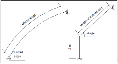
For the second type of column, a single armed Y shape, the same cases were studied as follows (i-iii):
i. Length: for the Y shaped column, only the length of the arm was changed. This was done based on 0.5m incremental. Firstly, the length was taken as 5.41m, then 5.91m and, lastly, 6.41m. The included angle was kept at 45 degrees. Boundary conditions at the lower end of the column was modelled as pinned, whereas the top end of the column was vertically free, but otherwise restrained.
ii. Boundary conditions: 3 cases were studied. Initially the bottom end of the column was modelled as pinned, but the top end was free vertically and restrained in all other directions. The length and the included angle were kept constant.
iii. Included angle: 3 different angles were studied with 10-degree increments. First off, the included angle was modelled as 40 degrees, then 50 degrees and, lastly, 60 degrees. The boundary conditions for these cases were such that the column was pinned at the lower end, whereas the upper end was modelled to be free vertically, but otherwise restrained.
The buckling load and the displacement of the columns were recorded in each of the cases to allow for the results to be established.
Verification of the FE model
The validation of the model was carried out in two ways.
i. By comparing the results of the model that was created to
the results of an experimental study into arches [21]. A model
arch was created similar to that which was used for the purpose
of the experimental study. The similar loading phase that was
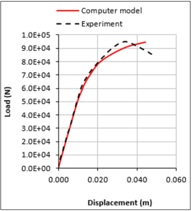
applied in the test implemented into the model. Figure 2 shows
a comparison of the results between the recorded displacement
at the top of the arch in the model and that of the experimental
study.
Figure 2:Load-Displacement curve comparison between FE model and Experimental study [21].
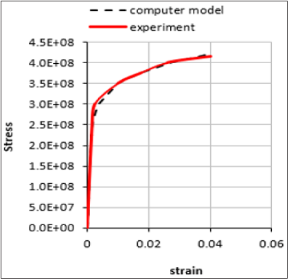
ii. Using the FE model, the stress-strain relationship was drawn as shown in Figure 3. The results closely matched those reported in the paper [21].
Figure 3:Stress-Strain curve comparison between results obtained from FE model and results obtained from experimental study [21].
The results of the FE model closely matched those of the
experimental study. Based on these, the results obtained from the
FE model was considered validated.
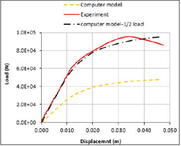
During the validation of the FE model, it was observed that
the displacement of the column was almost twice that of an arch
with similar properties and similar geometry. This is due to the
fact that an arch, if split at the midpoint, is essentially made up of 2
columns. Hence, it is reasonable for a column, which represents half
of an arch to show a displacement that is twice as big as that of the
arch under the same load. Based on this, the applied loads on the
columns were reduced by half to make them more reflective of the
reality of the cases as shown in Figure 4.
Figure 4:Comparison between displacement values for columns and arches.
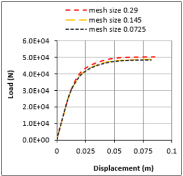
During the verifications of the model, a mesh sensitivity analysis was carried out to determine the effects of type of mesh used and the size of it on the eventual outcome of the modelling. Effects of different types of mesh was found to have negligible effects on the modelling of the columns. However, a slight variance could be seen when different mesh sizes were tested. This is shown in Figures 5 & 6. Based on the observation, a mesh size of 0.145mm was chosen. The element type used for this study was shear flexible elements since no significant change could be seen when other types of elements were tried out.
Figure 5:Effects of different types of mesh on the accuracy of the analysis.
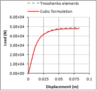
Figure 6:Effects of different sizes of mesh on the accuracy of the analysis.
Results and Discussion
After the validation of the FE model was achieved, the next stage
was to conduct the parametric studies to observe the effect of the
variables mentioned in the methodology section on geometrically
nonlinear columns
The column section that was used in this paper was identical to
the sections used in the validation of the FE model [21].
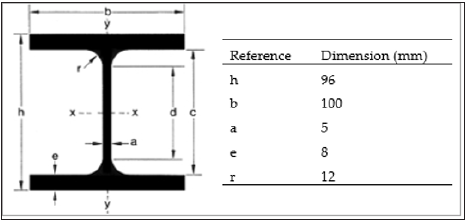
Columns were modelled using the validated FE model and were
given the dimensions shown in Figure 7 (HE 100 section). The
grade of the steel used for modelling was taken as S235 since these
sections are widely used in the construction industry.
Figure 7:Details of the section used for testing.
Loads were applied up to buckling point at increments of 1% of the original load, which was set to 1kN. Load-displacement was recorded, and the results are shown in the Figures below.
The results shown in Figures 8-13 confirmed the importance of geometrical nonlinearity (among other things) on the eventual load-carrying capacity of columns. The results highlighted how initial geometrical nonlinearities affect the load-carrying capacity of the columns, as has been reported in the literature [13,14, 24,26,32,40,41]. Significant differences were observed in the ultimate capacity of columns depending on whether the column was curved or Y shaped. Further investigation is required to explore this area in future studies.
Figure 8:Displacement curve comparison when the included angle is changed.
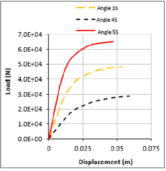
Figure 9:Displacement curve comparison when the included angle of the column is changed.

Figure 10:Displacement curve comparison when boundary conditions are variable.

Figure 11:Displacement curve comparison when the boundary conditions of the column is changed.
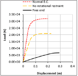
Figure 12:Comparison of displacement curves with when the column length is variable.
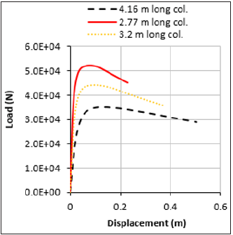
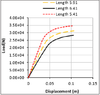
Figure 13:Displacement curve comparison when the length of the column is changed.
The study also shows a clear effect of the included angle on
the ultimate value of the load-carrying capacity of the columns. As seen in Figure 8, changing the included angle for the curved
columns from 55 degrees to 35 degrees resulted in a reduction
of more than 50% of the load-carrying capacity. This reduction is
further confirmed by the results of the Y shaped columns (Figure
9), although a less significant reduction was observed; of 30%. This
is in line with what other researchers have found [26,40].
From the results, it was also noticed that the columns started
showing nonlinear behaviour at similar stages based on the value of
the included angle. Pi et al. [26,40] reported similar observations for
the curved columns as shown in Figure 10. The load-displacement
curve started exhibiting nonlinear behaviour at roughly 45% of the
buckling load. Although the final value of the buckling loads was
different for each included angle, the ratio at which the columns
started displaying nonlinear behaviour remained roughly the same.
For the Y shaped columns, the columns started showing nonlinear
behaviour at just over 70% of their buckling loads. This is a stark
difference to what was observed in the curved columns.
Furthermore, the results shown for the columns which are
not restrained in any direction at the top indicate substantive
deformation under small loads. Out of plane buckling was the
mode of failure in this scenario (Figures 10 & 11). This finding is
in line with the established knowledge that cantilever columns and
arches lose a significant amount of load-carrying capacity if out of
plane displacement is not restrained [3,11]. However, having a nonrestrained
column that is geometrically nonlinear in buildings is not
very common. That is why all other cases investigated with some
form of lateral restraints applied to the top ends of the columns.
Additionally, it can be noticed that that the buckling load values
for columns increases with the increase of the included angle. This
points to the fact that classical buckling formulas could be used
up to a certain point when dealing with geometrically nonlinear
columns. Similar findings have been reported in existing literature
[8,9] But, as was noticed earlier (Figures 8 & 9), the change in the
buckling load value was not linearly proportional to the value of the
included angle. Hence, a linear formula for obtaining the buckling
load will lead to an overestimation of the actual load-carrying
capacity of the column.
La et al. [21] examined freestanding arches for in and outof-
plane buckling. In this paper, all the columns were supported
laterally at the top and the load was applied at the top except one
case that has been referred to above. This meant that the columns
were not susceptible for out-of-plane buckling.
The type of the restraint provided at the top has a remarkable
effect on the load-carrying capacity of the columns, as shown in
Figures 10 & 11. For the curved columns, when the top end was
laterally and rotationally restrained, the ultimate load capacity
of the column was measured at around 49kN. When the rotation
restraint was removed from this end, the ultimate load was
measured at just 23kN. This is a significant drop in the value of the
ultimate load-carrying capacity of the column. The observation is
also in agreement with the buckling theory and the influence of
boundary conditions on load-carrying capacity of columns.
For the single armed Y shaped columns, the reduction of the
pre-buckling load was observed to be less severe than it was with
curved columns. When the column was laterally and rotationally
restrained at the top, the buckling load that was recorded as 32kN.
When the boundary condition at the top was changed and rotation
was allowed, the value of the load dropped to 21kN.
Another interesting observation was made regarding the effects
of the shape of the columns on the pre-buckling behaviour. As it
can be seen in Figure 12, the columns reach their ultimate section
capacity before the nonlinear behaviour starts to develop. This is
almost the case for all the examined specimens. This could be due to
the fact that the test specimens which are short columns with max
length of 4.16m. Due to that fact, the column fails in compression
rather than buckling [3,11,15]. It is, therefore, suggested that any
future studies investigate a wide variety of lengths to be able to
reach a definitive conclusion.
The results shown for the Y shaped column, though, paint
an interesting picture as shown in Figure 13. In this Figure,
it can be seen that all the columns start exhibiting nonlinear
behaviour before reaching their ultimate load and fail in buckling.
Furthermore, all columns, regardless of length, started exhibiting
nonlinear behaviour at about 70% of their buckling load. This can
be interpreted by the fact that the Y shaped columns were slenderer
and were more likely to fail in buckling before reaching their section
capacity.
As noted in the first paragraph, this study underlines the
importance of carrying out separate investigations into each type
independently. Comparing results on two different cases against
each other is difficult and might lead to inaccurate conclusions.
It remains to be said that the number of tests carried out was
very limited. The parameters that were measured were buckling
load and displacement is known that many factors affect the loadcarrying
capacity of columns as has been shown in the results,
regardless of whether these columns are traditional geometrically
linear columns or nonlinear ones similar to what has been covered
in this paper. Drawing generalised conclusion, hence, will be
difficult from this limited study.
Therefore, the authors of this paper recommend further
investigation into this subject. Areas that have been identified for
future studies are as below:
i. The effects of different forms of geometrical nonlinearity;
this paper investigated only two forms of geometrically
nonlinear columns. Other forms should be explored and
understood fully before an informed conclusion regarding the
design approach could be made.
ii. This paper considered only open steel sections. Further
studies are needed on other types of sections that are commonly
used for columns. It is recommended that large scale studies
carried out into the behaviour of each type independently, since
comparing one type against another may lead to ambiguous
and inaccurate conclusions.
iii. Carrying out an experimental study where columns can
be fabricated as full-scale columns. This is very beneficial for
any future studies in terms of validating FE models that could
be used for further investigation. It also provides an important
insight into the behaviour of columns since man-fabricated
columns have a larger degree of inaccuracy than those examined
through FE modelling.
iv. Undertaking further studies to determine the influence of
different types of loading on geometrically nonlinear columns.
In this paper, only one type of loading was examined. Different
kinds of loads are applicable to columns in reality and they may
act separately or together on the columns. The effects of such
scenarios will have to be investigated further.
v. Any future studies should take into account a wider range
for each of the variables considered. This allows researchers
to make solid conclusions in light of a bigger pool of data and
would be statistically more reliable.
vi. Further studies regarding geometrically nonlinear
columns with different types of material; This paper considers
the behaviour of steel open sections only. However, A wide
range of various materials are used to fabricate/erect columns
in the construction industry. This is an area that can be studied
further.
As highlighted above, this paper studied only a small number of samples. Thus, developing an appropriate and fully tested design approach based on the results of this study is likely to be inappropriate/inaccurate [41].
However, from the results it can be seen that there is a similarity
between the behaviour of geometrically nonlinear columns and
arches. With the out-of-plane buckling mode being ruled out by
restraining the top end against lateral movement, other parameters
such as buckling mode, included angle and length showed similar
results to what has been shown in previous studies investigating
arches [21]. Therefore, after accounting for appropriate correcting
factors, it is possible utilise the available guidance in different codes
of practices to estimate the load-carrying capacity of geometrically
nonlinear columns. This, it is emphasised, requires further studies
and further testing to be carried out in order to allow for making
confident conclusions.
The available design codes ambiguously refer to the effects of
geometrical nonlinearity during the design process. In Eurocode
[3], the fundamentals formula that is adhered to is the notion
that design loads should be less than the design resistance of the
columns. This is expressed as below:
MEd≤ MN,R
Where,
MEd is applied design moment
MN, Rd=Mpl, Rd [1-(NEd / Npl, Rd)2]
Mpl, Rd is Plastic moment capacity of the section
Npl, Rd is Squash load of the section
Clause 5.5.4 (1) of the Eurocode 3 provides an interaction formula to cater for the combined effects of axial and flexural stresses

Ky is a factor to allow for the effects of the secondary moments, non-uniform moments and spread of yield.
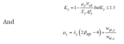
with its value bigger not bigger than 0.9
It can be seen from above that the Eurocode vaguely refers to
the effects of non-uniform moments on the load-carrying capacity
of columns. This, however, does not explicitly account for the effects
of nonlinear behaviour of columns which are caused by geometrical
nonlinearities, such as depth to span ratio.
The Eurocode does, however, provide charts and design curves
to enable the design of arches. These design curves do consider
geometrical nonlinearities.
In Annex D.3 of BS EN 1993-2 [11], The formulas for estimating
in plane and out of plane bucking loads are given for arches. The
formula, unlike those specific to columns, allows for the effects of
depth to span ratio. This has been achieved by including a buckling
length factor for most common forms of arches.

Ncr is the max compression force at the supports that the arch can support
βs is buckling length factor which is given in appendix D3.2 in Eurocode 3
The formula above, which is provided in Eurocode 3, is to obtain an estimate of the critical compression load at the supports. As can be seen, the formula allows for the effects of rise/span ration by including the buckling length factor (βs). The buckling length factor curves is given in appendix D3.2 in Eurocode 3.
Conclusion
Behaviour of geometrically nonlinear columns, despite their
wide use in the construction industry, remains vaguely understood
as has been outlined in the introduction section of this paper.
Design codes and guidance available do not offer explicit formulas
to deal with geometrically nonlinear columns; but rather a design
approach for members which are curved in the plane of the load
[3,10,11]. These formulas could be used to estimate the loadcarrying
capacity of arches accurately considering that they have
been developed for arches. The authors of this paper are concerned
that using these formulas could lead to an over estimation of the
load-carrying capacity of geometrically nonlinear columns.
In this paper, the authors aimed at shining a light on the
behaviour of geometrically nonlinear steel columns and the factors
affecting its load-carrying capacity. Two cases were considered: a curved column and a Y shaped single armed column. These columns
were modelled using a validated FE model that was created using
Abaqus. Using this model, the effects of three factors were studied
on the load-carrying capacity of the columns. These factors were:
A. Length: For the curved columns the length of the entire
column was considered. For the Y shaped columns, the length
of inclined part was considered.
B. The effects of support conditions.
C. The effects of the included angle (i.e., changing depth/
reach ratio).
D. After the parametric studies were carried out, the
following was observed:
E. The two cases that were chosen to be studied were behaving significantly different to each other. For instance, changing the included angle for curved columns from 55 to 35 results in a capacity reduction of over 55%, whereas changing the angle from 60 to 40 in Y shaped column results in 40% reduction (see Figures 8 & 9). It was also noticed that curved columns and Y shaped columns start exhibiting nonlinear behaviour at different stages of their load-carrying capacity. This signifies the importance of carrying out further studies into each type of column independently to avoid any ambiguity and be able to make confident conclusions.
F. The effects of included angle on the load-carrying capacity
of nonlinear columns: the results show that this factor affects
the capacity of columns significantly. This is similar to studies
carried out reading the behaviour of arches previously [8].
G. Boundary conditions were observed to also have an effect
on the load-carrying capacity of nonlinear columns as shown
in Figures 10 & 11. Columns that were modelled as free at the
top end were observed to fail in out of plane buckling. This is
a similar behaviour to steel arches investigated by previous
studies [21].
H. Effects of length: for the curved columns, the modelled
columns reached their section capacity before displaying
nonlinear behaviour. Y shaped columns, on the other hand,
started displaying nonlinear behaviour at about 70% of their
capacity load. This has been shown in Figures 12 & 13.
Current design codes do not, to the knowledge of the authors,
explicitly state a formula for design of geometrically nonlinear
columns. What is provided is guidance on the design of steel
members which are curved in in the plane of loading. This has been
discussed in section 5 of this paper.
Having shown, in the results, the similarities in behaviour of
nonlinear column to that of arches, it can be concluded that the
design curves produced for arches can be utilised, with a great
degree of confidence, to estimate the load-carrying capacity of
nonlinear columns.
Nonetheless, it is important to remember that that the available design formulas and curves are produced for the design of arches. These cannot be used for the design of nonlinear columns without any correction. These charts can be used as a basis for developing formulas specific to nonlinear columns, after allowing for appropriate corrections.
References
- Austin WJ (1971) In-plane bending and buckling of arches. Journal of the Structural Division 97(5): 1575-1592.
- Simitses G, Hodges DH (2006) Fundamentals of structural stability. Butterworth-Heinemann, New Hampshire, USA.
- Standard B (2006) Eurocode 3-Design of steel structures. BS EN 1993-1,1: 2005.
- Timoshenko SP, Gere JM (2009) Theory of elastic stability. Courier Corporation.
- Rush DI, Bisby LA, Jowsey A, Lane B (2015) Residual capacity of fire-exposed concrete-filled steel hollow section columns. Engineering Structures 100: 550-563.
- Rush D, Bisby LA, Jowsey A, Melandinos A, Lane B (2012) Structural performance of unprotected concrete-filled steel hollow sections in fire: A review and meta-analysis of available test data. Steel & Composite Structures 12(4): 325-350.
- Janss J, Minne R (1981) Buckling of steel columns in fire conditions. Fire Safety Journal 4(4): 227-235.
- Komatsu S, Shinke T (1977) Practical formulas for in-plane load carrying capacity of arches. In: Proceedings of the Japan Society of Civil Engineers. Japan Society of Civil Engineers, Tokyo, Japan.
- Sakimoto T, Komatsu S (1983) Ultimate strength formula for steel arches. Journal of Structural Engineering 109(3): 613-627.
- King C, Brown D (2001) Design of curved steel. Steel Construction Institute Ascot, UK.
- BSI, BS EN 1993-2 (2006) Eurocode 3. Design of steel structures. Steel bridges, BSI London, UK.
- Pi YL, Bradford M (2004) Effects of prebuckling deformations on the elastic flexural-torsional buckling of laterally fixed arches. International Journal of Mechanical Sciences 46(2): 321-342.
- Pi YL, Trahair NS (1996) In-plane inelastic buckling and strengths of steel arches. Journal of Structural Engineering 122(7): 734-747.
- Verstappen IMW, Snijder HH, Bijlaard FSK, Steenbergen HMGM (1998) Design rules for steel arches-in-plane stability. Journal of Constructional Steel Research 46(1-3): 125-126.
- Bild S, Trahair NS (1989) In-plane strengths of steel columns and beam-columns. Journal of Constructional Steel Research 13(1): 1-22.
- Bradford MA, Pi YL (2006) Flexural-torsional buckling of fixed steel arches under uniform bending. Journal of Constructional Steel Research 62(1-2): 20-26.
- Bradford M, Uy B, Pi YL (2002) In-plane elastic stability of arches under a central concentrated load. Journal of Engineering Mechanics 128(7): 710-719.
- Pi YL, Bradford MA (2003) Inelastic buckling and strengths of steel I-section arches with central torsional restraints. Thin-Walled Structures 41(7): 663-689.
- Pi YL, Bradford MA, Uy B (2002) In-plane stability of arches. International Journal of Solids and Structures 39(1): 105-125.
- Galambos TV (1998) Guide to stability design criteria for metal structures. John Wiley & Sons, New York, USA.
- La Poutre DB, Spoorenberg RC, Snijder HH, Hoenderkamp JCD (2013) Out-of-plane stability of roller bent archesan experimental investigation. Journal of Constructional Steel Research 81(1): 20-34.
- Ojalvo M, Demuts E, Tokarz F (1969) Out-of-plane buckling of curved members. Journal of the Structural Division 95(10): 2305-2318.
- Pi YL, Bradford MA (2001) Strength design of steel I-section beams curved in plan. Journal of Structural Engineering 127(6): 639-646.
- Pi YL, Trahair NS (1998) Non-linear buckling and postbuckling of elastic arches. Engineering Structures 20(7): 571-579.
- Pi YL, Trahair NS (1998) Out-of-plane inelastic buckling and strength of steel arches. Journal of Structural Engineering 124(2): 174-183.
- Pi YL, Trahair NS (2000) Inelastic lateral buckling strength and design of steel arches. Engineering structures 22(8): 993-1005.
- Pi YL, Trahair NS (1994) Nonlinear inelastic analysis of steel beam-columns. I: Theory. Journal of Structural Engineering 120(7): 2041-2061.
- Pi YL, Trahair NS (1994) Nonlinear inelastic analysis of steel beam-columns. II: Applications. Journal of Structural Engineering 120(7): 2062-2085.
- Wei J, Wu Q, Chen B, Wang TL (2009) Equivalent beam-column method to estimate in-plane critical loads of parabolic fixed steel arches. Journal of Bridge Engineering 14(5): 346-354.
- Chen WF, Atsuta T (2007) Theory of beam-columns, volume 2: space behavior and design. J Ross Publishing.
- Pi YL, Bradford MA, Tin Loi F (2007) Flexural-torsional buckling of shallow arches with open thin-walled section under uniform radial loads. Thin-Walled Structures 45(3): 352-362.
- Pi YL, Bradford MA (2013) Lateral-torsional elastic buckling of rotationally restrained arches with a thin-walled section under a central concentrated load. Thin-Walled Structures 73: 18-26.
- Usami T, Koh SY (1980) Large displacement theory of thin-walled curved members and its application to lateral-torsional buckling analysis of circular arches. International Journal of Solids and Structures 16(1): 71-95.
- Ellobody E, Young B (2006) Nonlinear analysis of concrete-filled steel SHS and RHS columns. Thin-Walled Structures 44(8): 919-930.
- Hu HT, Huang CS, Wu MH, Wu YM (2003) Nonlinear analysis of axially loaded concrete-filled tube columns with confinement effect. Journal of Structural Engineering 129(10): 1322-1329.
- Liang QQ, Fragomeni S (2009) Nonlinear analysis of circular concrete-filled steel tubular short columns under axial loading. Journal of Constructional Steel Research 65(12): 2186-2196.
- Liang QQ, Fragomeni S (2010) Nonlinear analysis of circular concrete-filled steel tubular short columns under eccentric loading. Journal of Constructional Steel Research 66(2): 159-169.
- Hamed E, Lai C (2016) Geometrically and materially nonlinear creep behaviour of reinforced concrete columns. Structures 5: 1-12.
- Tomski L, Uzny S (2008) Free vibrations and the stability of a geometrically non-linear column loaded by a follower force directed towards the positive pole. International Journal of Solids and Structures 45(1): 87-112.
- Pi YL, Trahair NS (1999) In-plane buckling and design of steel arches. Journal of Structural Engineering 125(11): 1291-1298.
- Pi YL, Bradford MA (2004) In-plane strength and design of fixed steel I-section arches. Engineering structures 26(3): 291-301.
© 2021 Hussein Mohammed. This is an open access article distributed under the terms of the Creative Commons Attribution License , which permits unrestricted use, distribution, and build upon your work non-commercially.
 a Creative Commons Attribution 4.0 International License. Based on a work at www.crimsonpublishers.com.
Best viewed in


.jpg)


 Editorial Board Registrations
 Submit your Article
 Refer a Friend
 Advertise With Us
.jpg)


.jpg)


.bmp)
.jpg)
.png)
.jpg)


.jpg)


.png)

.png)


.png)


