- Submissions

Full Text
Trends in Textile Engineering & Fashion Technology
A Comparative Study on Different Dimensions of CAD
Shariful Islam1*, Zakia Urmy2, Amirul Islam1, Suza Ahmed1, Arif Billah3 and Rabeya Islam4
1Bangladesh University of Textiles, Bangladesh
2University of Dhaka, Bangladesh
3University of Chittagong, Bangladesh
4City University, Bangladesh
*Corresponding author: Shariful Islam, Bangladesh University of Textiles
Submission: January 06, 2018; Published: February 06, 2018

ISSN: 2578-0271 Volume1 Issue1
Abstract
The aim of this paper is to introduce different CAD of different dimensions and configurations. A CAD may have some dimensions based on its shape and nature. This project can be helpful to person related to doing textile design, research and practice on textile real filed. Quite a few types of dimensions are noticed for various objects in numerous alignments, directions, orientation arrangements and configurations. The elementary types of dimensions are linear, radial, angular, ordinate, and arc length. Configurations are strongly dependent on the objects, types, nature and shape. It is possible to measure the dimensions of CAD by its real appearance in surroundings. Configuration describes to identify the reality, shape, directions, orientation and arrangements with its basic standard. Also, a CAD has some dimensions like length, width and height those are discussed in this paper and learners can be helpful to know this.
Keywords: CAD; Dimensions of CAD; 2D CAD; 2.5D CAD; 3D CAD; 4D CAD; 5D CAD
Introduction
The importance of this project is many [1]. CAD or CAD software is used to enhance the productivity of the designer, to make better the quality of design, to improve communications through documentation, and to create a database for manufacturing. Basically, output of CAD is like electronic files for printing, machining, or doing manufacturing operations. CAD is "Computer Aided Design", which is mainly used in fabric manufacturing unit, by loom machine to input weave structure, drafting plan and lifting plan through weave CAD software [2]. This software system of "CADD" is mostly used to manufacture or construct the predictable designed fabric. On the other hand, CAID is "Computer Aided Industrial Design", which is generally used in textile industries to manufacture textile goods. This software is also used to interpret computerized designing that includes both software and hardware system. "CADD" and "CAID" software helps to visualize and get the artistic or creative design in absolute form, without manufacturing any sample swatch [3]. Designers convert the useable CAD into workable designs. Industrial designers most often use CAD to form 2D or 2.5D vector base drawings, which express the dimension and appearance that is yet to be manufactured. CAD drawing shows how an object is constructed and proposes improved visualization of the design that increases accurateness and also eradicates miscalculation for the duration of built-up practice. In a plain language, CAD is the use of computer software for designing. Linear dimensions are horizontal, vertical, or aligned. Rotated dimensions are the dimension line that is placed at an angle to the extension line original points. A radial dimension measures the radius or diameter of arcs and circles. Angular dimensions measure the angle between two selected geometric objects or three points. Arc length dimensions measure the distance along an arc [4].
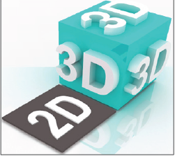
Figure 1: 2D and 3D shape.
Types of CAD: Many types of CADs are available based on dimensions as discussed below:
A. Two Dimensional (2D CAD)
B. Two and a Half Dimensional (2.5D CAD)
C. Three Dimensional (3D CAD)
D. Four Dimensional (4D CAD)
E. Five Dimensional (5D CAD) (Figure 1-4)
Figure 2: 2D conceptual drawings.
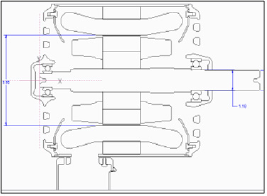
Figure 3: 3D conceptual design.
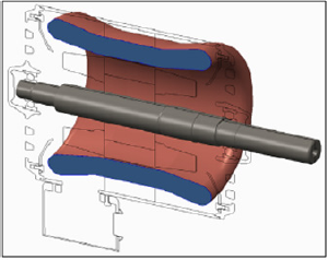
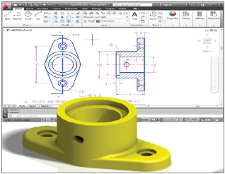
Figure 4: Drawing of 2D and 2.5D from 3D real object.
2D CAD
Two dimensional computer aided design is the most basic type of CAD program. Two Dimensional or 2D CADs are used to create flat drawings of products and structures. Objects that are created in 2D CADs are made up of lines, circles, ovals, slots and curves. The designers create the drawings by plotting along X any Y-axes. Designs have no depth to them, being displayed by their outlines only [5]. These types of programs are useful for architects, and other professionals who do not need any depth to provide a representation of their creations. Among the most popular 2D CAD programs are AutoCAD, CAD key, CADDS 5, CATIA V4, and Medusa. In textile industries, we are using 2D CADs for designing and patterning (Figure 5).
Figure 5: 2D plan of a floor.

2.5D CAD
Two and a Half Dimensional or 2.5D CADs are in between 2D and 3D. The models that are made by these CADs are like prism that has depth in its objects. This is basically done through isometric projection that creates a false sense of depth. These CADs allow the users to create three-dimensional drawings in two-dimensional 2D surface. Actually this is a 3D drawing on 2D surface (paper) [6]. Some figures of 2.5 D are given below. The drawings of real object in paper, which shows and describes the length and width, along with a false sense of height/depth (thickness), that drawings are called 2.5D CAD (Figure 6).
Figure 6: 2.5D CAD showing a false sense of height along with length and width.
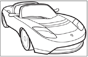
3D CAD
Three Dimensional CAD programs are very costly; they have a wide verity of types, proposed for dissimilar applications. They may use nurbs, wire frames or solids to create truly 3D drawings architectures. This design has true depth in its arrangement, which allows the designers to rotate his designs 360 degrees around three different axes. This 3D CAD represents the best accurate representation of how it will look when it will be truly produced. Some 3D CAD programs contain Autodesk Inventor, Co Create solid designers, Pro/Engineer Solid Edge, Solid Works, Uni Graphics NX and, VX CAD. Actually, 3D Model is a representation of a three-dimensional surface using specialized software that combines the height, width, and depth of the space illustrated.3D CADs are the real or truly miniature of a large substance [7]. The below mentioned figures will be 3D CADs if and only if, they can be laid a hand on three-axes (must be a three dimensional touchable product that can be touched by three real dimensions, not a picture only) and also if they are become real miniature substance of larger things. 3D CAD models are the closed representation of the finished products (Figure 7 & 8).
Figure 7: 3D shows three real dimensions through a real object in miniature form.

Figure 8: 2D and 3D section.
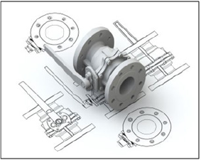
Types of view from 3D models
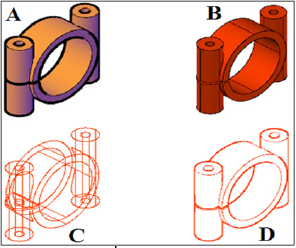
It is possible to create a shaded, a hidden and a wireframe mode from a 3D model. This view can contain an arrangement of solid, surface, and wireframe geometry (Figure 9).
Figure 9: Conceptual, realistic and wireframe view.
4D CAD
Four Dimension (4D) suggests to the fourth dimension that is time/schedule along with 3D CAD. 4D is the clarification of {3D + schedule (time)}. 4D is a form, for 4D Building Information Modeling, which refers to the linking of individual 3D CAD components with time, timetable or schedule related information [8]. 4D allows different partakers, from engineers and designers, to the proprietor of a manufactured project, to visualize the total period of actions and to show the advancement of structural actions from beginning to end of the lifetime of the project. So, 4D = 3D (X, Y, Z) + Time.
4D CAD Models generate connection with 3D CAD models, through actions from the design, procurement, and structural timetable. Project of 4D model allows the project stake-holders to observe the designed construction, through the passage of times on the screen (Figure 10).
Figure 10: 4D idea with the passage of time.
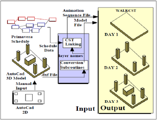
4D brings technologies that support the demands of the construction of large-scale and complex projects like high compartment, over-passes, high-streets, sub-ways, academic campus, hospitals, complex buildings, duplex housing, court-houses etc. Actually, 4D CAD adjoins a new dimension in 3D CAD or solid modeling that connects a new fourth dimension of Time in 3D Space of CAD solid modeling on computer [9]. 4D CAD is compatible with Mac OS, Mac OS X and Windows. Actually, 4D Model is a 3D model intelligently linked with time or schedule related information for a project.
Development of 4D CAD model: There are some processes to develop a 4D CAD model, which are discussed below. At first, develop a 3D CAD model and then develop a construction schedule plan. Separate the 3D CAD model into appropriate construction elements. Connect the mechanism of the 3D model with their activities specified by a 4D CAD schedule. Just the once they are linked up the 4D CAD model can be viewed as an imitation of the construction plan.
Uses of 4D CAD: 4D CADs are used as a substitute of 4D Drawings, as an entirely programmable CAD engine, as a graphics engine and graphics-programming engine etc. 4D CAD models allow the people to realize a schedule plan easily and rapidly and also to discover the probable troubles, as it permits people to think about the construction process earlier, because it would be really built previous to the construction starts [10]. 4D CAD models are helpful to express which components are being built at which time along with location.
4D model aids with coordination of subcontractor schedules. 4D model permits all the members of the squad to visualize their tasks and the relationships that exist between the works of the different sub-trades. The 4D model clearly communicates schedule intent. 4D models provide a useful way to communicate the schedule to the different project stakeholders [5]. The 4D model communicates workflow over time. 4D models provide a superior way of communicating work flow over time compared with conventional bar-chart schedules. 4D models help identify constructability issues and sequencing problems prior to construction.4D models show the status of construction at any time in the project.
Figure 11: 3D, 4D and 5D concept (A).
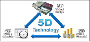
4D CAD models are effective in-- to confirm the completeness of the schedule plan, to find out the inconsistency in the level of details among the schedule activities and schedule sequence, to find out any impossible schedule sequences, to identify the potential time- space conflicts, to evaluate the execute ability of a construction schedule and to anticipate accessibility problems.
Special use of 4D CAD models: 4D CAD models permit the users to identify errors or potential problems just before the construction procedure. 4D CAD models now are being used in huge projects and process plants. Companies are becoming conscious about the benefits and they are starting to investigate the possibilities as a means to amplify their competitiveness (Figure 11).
5D CAD
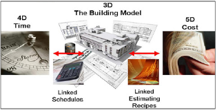
X and Y axes express 2D on paper with length and width; 2.5D creates a false sense of depth in 2D surface along width length and width; X, Y and Z axes express 3D with real length, width and depth; Adjoining time with 3D creates 4th dimension that is 4D; where- by adding together the financial cost data with 4D, creates a 5D platform process [11]. 5D is a project delivery process for all phases of construction process, virtually eliminating the need for duplication in effort that reduces cost. 5D proposal enables an organization and their teams to transform their project delivery, earlier than a planned period of time that increases effectiveness and efficiencies to the project delivery process. [Therefore 5D = 3D (X, Y, Z) + 4D (time) + Cost.] Actually, 5D Model is a 4D model intelligently linked with cost information for a project (Figure 12).
Figure 12: 3D, 4D and 5D concept (B).
Conclusion
Actually, Computer Aided Design or CAD is used by architects, engineers, drafters, artists, and others to create precision drawings or technical illustrations. CAD software can be used to create twodimensional (2-D) drawings or three-dimensional (3-D) models. CAD is a technology for design and technical documentation, which replaces manual drafting with an automated process. CAD helps to construct documentation, explore design ideas, visualize concepts and simulate how a design performs in the real world. CAD allows engineers to design variants with nominal physical models to achieve lower product development costs, better speed, better productivity, quality guarantee, faster time-to-market.
References
- Greenwood k and Vaughan g (1959) 19-The effect of weft yarn irregularity on picks pacing and weft cover factor. Journal of the textile institute transactions 50(5): 337-352.
- Dormor C (2014) Warp & weft: woven textiles in fashion, art and interiors, Jessica hemmings. Textile 12(2): 255-257.
- Lomax J (1949) A suggested method of testing woven fabrics for measurement of resistance to slippage of warp threads over the weft, or weft over the warp. Journal of The Textile Institute Transactions 40(8): 525-526.
- Karnoub A (2015) The effect of warp and weft variables on fabric's shrinkage ratio. Journal of Textile Science & Engineering 5(2).
- Zhang Z, Yu C (2011) Study on drafting force and sliver irregularity on drawing frame. Journal of The Textile Institute 103(3): 1-7.
- Mcmahon J (1986) Weft tension during double-rapier weft insertion in weaving. Journal of the Textile Institute 77(5): 356-358.
- Garaventa D (1981) A discontinuous warp and weft textile of early horizon date. Nawpa Pacha, 19(1): 167-176.
- Tevis J (2015) Warp and weft. Places Journal.
- Ghosh G And Bhaduri S (1962) Dependence Of Hook Removal At Drawing On Some Drafting Parameters. Textile Research Journal 32(10): 864-866.
- Hartley H (1926) 25-fabric analysis-the contraction of warp and weft. Journal of Textile Institute Transactions 17(5): 254-258.
- Kendall F (1949) The institute is not responsible for the opinions of correspondents. A suggested method of testing woven fabrics for the measurement of resistance to slippage of warp threads over the weft, or weft over warp. Journal of The Textile Institute Transactions 40(4): 247-252.
© 2018 Shariful Islam. This is an open access article distributed under the terms of the Creative Commons Attribution License , which permits unrestricted use, distribution, and build upon your work non-commercially.
 a Creative Commons Attribution 4.0 International License. Based on a work at www.crimsonpublishers.com.
Best viewed in


.jpg)


 Editorial Board Registrations
 Submit your Article
 Refer a Friend
 Advertise With Us
.jpg)


.jpg)


.bmp)
.jpg)
.png)
.jpg)


.jpg)


.png)

.png)


.png)


