- Submissions

Full Text
Research & Development in Material Science
The Sway of Effect Pulse Energies of LSP Pathways on AHSS-DP 350/600
Baidoo Philip*
Department of Mechanical & Automotive Technology Education, University of Education, Ghana
*Corresponding author: Baidoo Philip, Department of Mechanical & Automotive Technology Education, University of Education, Winneba, Ghana
Submission: November 25, 2019;Published: December 03, 2019

ISSN: 2576-8840 Volume 12 Issue 3
Abstract
Fatigue crack growth test was executed to determine fatigue behavior in the metallic plates of AHSSDP350/ 600 however, this new material is widely used this day in automobile manufacturing industry henceforth controlling fatigue character is a major challenge in the production unit. The influence of laser shock peening with multiple choice of pulse energies on AHSS-DP350/600 was investigated and its improvement of material properties was the ultimate objective. Measuring compared of both residual stress and fatigue cycle behavior, observation of morphologies, impact hardness of facture surfaces and roughness/damage fractal was performed. It resulted that the compressive residual stress can be injected into the outer layer of the specimen, with LSP pulse energy of S20J, S30J, D20J, and D30J. It again indicated that shocking pulse of square sharp edge introduced tiny cracks on the outward layer which the wave’s inner compressive residual stress vice versa with enclosure significantly stepped up with enlargement of LSP coverage area. LSP sample of D30J significantly revealed higher influence among other specimens.
Keywords: AHSS-DP350/600; Laser shock peening; Fatigue crack growth; Pulse energy; Residual stress; Fatigue crack initiation
Introduction
Laser shock processing (LSP) is accountably novel material outward layer body modification technology. It employs high power laser to inflict a well-built hit wave on material outer body layer to refine the material structure and induce residual stress beneficially into outward appearance Cheng et al. [1] worked on the effects of LSP on Nano-hardness, elastic modulus and surface residual stress of Fe-Ni alloy and investigated. The importance of tiny-hardness and elastic modulus on Fe-Ni alloy after LSP were measured by the Nano indentation technology. The marked residual effort outward layer by XRD with sin2ψ and scanning electron microscopy (SEM) observation of the microstructure before and after LSP solutions were captured. Execute resulted that outer appearance of the tiny-hardness, elastic modulus and outward residual effort in LSP region, were obviously raised to a desirable point as against non-LSP region. Banderas et al. [2] emphatically alarmed on a paper the negative side of an absorbent overlay on the residual stress field using LSP setup and the energy level were evaluated. The Residual defects spread in multiples have a character of inner depth governed by the drilling behavior. It was seen that the overspread of residual stress move the write-about to a position changed on the outer side on the specimen. The prevention of coating the specimen surface after LSP have improved wear and contact fatigue properties of this aluminum alloy. Guan et al. [3] confirmed also in the work done on tiny-indentation used to handle measuring tiny films on mechanical properties, including elastic modulus and tiny-hardness. The pithy-hardness and elastic modulus samples manufacture have a series of effects by LSP during LY2 aluminum alloy worked. The outcome of the result shown Nanoindentation techniques values increased by 58.13% and 61.74% as compared to non-LSP. LPS improved metal mechanical strength which governed fatigue property and corrosion resistance were alarmed. Hill et al. [4] investigated that the advance-cycle fatigue feats in accordance with 7085-T7651 aluminum treated with a sample of LSP and anodization. The Stress-feats and fatigue-data were ignited in a high-level humidity environment which used smooth (Kt = 1) specimens test at a stress ratio (R= 0.1). This resulted that shocked specimens chanced-out higher significant improvement in fatigue performance.
However non-anodized specimens had a value of 5-14 extension fatigue life per stress level conformity and anodized specimens had a value of 8-9 extension per fatigue character. Non-LSP anodized had reduced fatigue character at most stress locational levels. The LSP anodized and non-anodized specimen have unique-similar characters at high stress (life < 105 cycles) but anodized one had limited lives at lesser stress. Curtis et al. [5] emphasized that the characteristic of LSP and dual-LSP treatment on the fatigue style of 2024-T351 was done. The test showed that fatigue character of life and improvement affected the three cases of LSP and dual treatment displaying fatigue performance superior shot peened. The fractographic analyzed that proportionate lesser character of the LSP was caused by ductility loss. Berthe et al. [6] made a clearer revealed that 55C1 steel was irradiated with a highpower neodymium-glass laser with application to induce plastic shock waves within targets. LSP experiments were confirmed in plasma-confined regime with water to step-up LSP-induced peak value stresses. Physical and mechanical processed were reviewed to characterized stress oscillation coated steels with a VISAR velocimeter system. The changes governed 55Cl residual stress and hardiness of convenient protective coatings 7-8 GPa peak value stress levels were achieved which authorized the generation. The upper residual stress score of 80% yield strength kept outward layer integrity from detrimental roughening. Surface mating new lifestyle is done in accordance with different suit LSP were 30% step-up on bending fatigue limits. Cui et al. [7] worked on LSP treated tensile made agreement with material manufactured by 7050 aluminum (Al) alloy. The first grouped sample was treated by two paths of shocks and second by four of paths of shocks. Experimental resulted that the fatigue lives off the second grouped stepped-up among others. Comparatively traditional processed techniques can directly handle the treatment location and its deeper depth. Harris et al. [8] during their work on “Surface pre-stressing to step up fatigue strength of components by LSP”. It’s a competitive technique which provides multiple robust governed fatigue. Dai et al. [9] made this statement that to charmed fatigue improvement on structure material, LSP must use the effects of residual stress on fatigue behavior.
The crack propagation of LSP worked hole marvelously good during this investigation. The changed location microstructure of 7050 aluminum at different intensities shown that LSP had an obvious inhibitory action to crack initiation and growth respect to fatigue. These investigations have verified that LSP attempted to minimize the condemned fatigue crack paths (FCP). However, the researches focused on a comparative study on different pulse energy levels of AHSS-DP 350/600 peak outrage influence concernment on fatigue. In order to satisfy this requirement, a dog bone specimens in Figure 1 non-LSP and LSP of different energies of 20J and 30J on a single-sided LSP impact and single double sides LSP impact named: (S20J; S30J; D20J; and D30J) and non-LSP impact were done on specimens before the following tests: hardness, roughness, residual stress, fatigue cycle, and microstructure morphologies.
Figure 1: a) Specimen drew dimensions and b) LSP paths.

However, up to date, few works eliminated fully the amount of percentage of delay time to forming micro-crack accounts for the prolonging fatigue life contributed by LSP energies in a comparative manner. Therefore, LSP energies enhancement of fatigue property was investigated. Comprehensively the affected of LSP on crack forming and its propagation behavior of stiffness/ rigid, martensitic and bainitic in AHSS-DP 350/600 plate were also investigated. The deformed outer body layer was studied governed the demonstration of the fatigue crack initiation sites and fatigue crack spacing thereby fatigue benefits offered by LSP have been revealed in AHSS-DP 350/600.
Experimental Procedures
The automobile, transportation industry now highly uses AHSSDP 350/600 plates which have a good low-temperature impact, homogeneous microstructure, good cool forming performance, low ductile-brittle transition and finally good resister to corrosion. AHSS-DP 350/600 is used under the harsh environment of automotive industries and transportation platforms. The chemical composition and mechanical properties of AHSS- DP350/600 were shown in Table1 & 2; [10].
Table 1: Mechanical properties of AHSS-DP350/600 [16].

Table 2: Chemical properties of AHSS-DP350/600 [16].

Improving fatigue property of AHSS-DP 350/600 plays a pivotal role in prolonging material service life, and LSP is a novel antifatigue technology for a betterment expansion of metal dis-fatigue life function in both span and periodic cycles. According to GB/ T6398-2000 experimental conditions on the dog bone specimens prepared with the dimensions shown in Figure 1, to do reconnoiter on the effect of LSP on the FCG rate on AHSS-DP 350/600. The positions of the LSP zone, for AHSS-DP 350/600 were carefully marked by marking pen input to distinguish from different zones treatment. The below steps shown were used to handling the specimens:
a) Cutting specimens at stated dimensions by electrodischarge machined (EDM);
b) Grinding and polishing samples with SiC paper at different grades of roughness;
c) Cleaning samples in deionized water and saving in drying box;
d) Eliminating machined surface residual stress of dog bone specimens by naturally aging treatment for a particular interval of time.
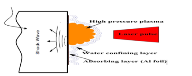
Principle of LSP and experimental parametersThe LSP utilized a heavy energy laser pulses to hit the outer body layer of material and then formed a plasma. The restrained plasma created a maximum outer ward layer force propagating into the material as a shock wave. When the force of shock wave hammered the dynamic yield strength of the material, it produced a change of plastic state in the near-outward body layer. This adopted LSP principle was schematically availed in Figure 2. The volume LSP impacts in the temped zone of the dog bone of AHSS-DP 350/600 were carried out using a Q-switched Nd: YAG (Neodymium doped Yttrium Aluminum Garnet). A numerical control workbench was used to handle specimens. All samples were sunk into a water bath when they were processed by LSP. A water outer layer with thickness almost 1mm was used as a transparent confining layer. Professional aluminum foil thickness of 0.1mm was used to absorbing the layer from damaging sample surface. The following were LSP parameters used: laser energies 30J &20J; pulse width 15ns; spot diameter/ square 4*4mm2; spot spacing 3.4mm; laser densities 12.5gw/cm2 and 6.25gw/cm2.
Figure 1: Schematic principle of LSP.
Measurements of residual stress
Prior to measure the residual stress, the specimens were cleaned manually by ethanol to remove the sticky aluminum foil produced during LSP. All readings on residual stress championed by X-ray diffraction with sin 2Ψ method. An X-ray tube with a chrome anode operated at 22.0kV was used. The X-ray beam diameter was nearer to 2mm and the source was Cr Ka ray. The feed angle of the ladder scanning was 0.5s. The scanning starting angle and terminating angle were 163.00 0 and 148.000 respectively. Measurement done equally on LSP regions parallel to the laser swept direction over the central hole. Each test point was repeatedly three times on both sides.
Rockwell hardness testStudies have proofed that despite a lot of testing system for indentation, this methodological test among the effective and efficient indentation hardness tests was used. This test uses measurement deformation characters happens when the material before test governed by penetration steps with a specific type of indenter. Dual forces in conformity are applied differently to the indenter at specified rates of different points and with specific dwell times. This material is governing with different accordance in an inner indenter at periodic intervals of times during the testing cycle. The values governed by measurement that derived constantly to yield a number falling within an arbitrarily defined range of number known as the Rockwell hardness scale. The indenter brought to alignment and mesh with material and an initial load of force was applied. The initial force hold-up time (dwell time) was applied whiles the depth of indentation read. The additional force applied to step-up the previous force as a major load. The applied force was pended for a particular interval of time and after that force reduction which returns to the previous force level. This work done the used force of 150gf in 10s.
Roughness structure observationThe outward body layer integrity talks about the influential of material outward property and condition upon its performance. Its cleary understood that the method used for outward body layer material finishing and its multiplex merging roughness residual stress were strongly in accordance with the fatigue corrosion style of materials. The roughness measurement-work influence of outward body layer finishing done on materials characteristically was picked for the most critical applications.
Fatigue test equipmentFatigue tests were conducted for different energies of both sides of single impact and double-sided impact shocked specimens as against non-shocked on an electro-hydraulic servo control machine phased same environmental condition respectively. This experiment took place under a constant load amplitude of 18.2 KN, 3 Hz of frequency governed by the ratio of 0.1 in normal room temperature.
Fracture morphologies observationThe fractured end of the bracken specimen’s outward layer was cleaned after the fatigue cycle test and kept for the normal dried system after careful studies captured by SEM, JSM-6490LV.
Results and Discussion
LSP process normalizes and injected massive density welldistributed and stationed dislocations, which may cause lattice distortion and generate high amplitude compressive residual stress highly-involved the fatigue deformation limitation. Chen et al. [11] emphasized the style of mechanical properties and fatigue signals deformation on the morphology of aluminum (6061-T6) govern by LSP. Resulted in that fatigue live outcome subjected to an influential LSP value. The value increased with the increase of the impact number. LSP transformed the location of fatigue crack initiation (FCI) from upper outward body layer to sub-outer body layer and changes in accordance with an increment of the impact number. Gu et al. [12] reported that the structural value of micros after evolution grain refinement in ANSI 304 stainless steel transformed to multiple LSP impacts. More on multidirectional twin matrix (MT) of mechanical properties and these intersections led to grain subparts at the top outward body layer during multiple LSP impacts. Furthermore, a novel structure with sub-micron triangular blocks was found at the upper outward layer of the sample which subjected to three different LSP impacts. Stacking challenges in accordance with multiple layouts due to the pile-up dislocation layers and formation of sub-micron triangular blocks by the intersection of MT-MT in conformity with multiple directions.
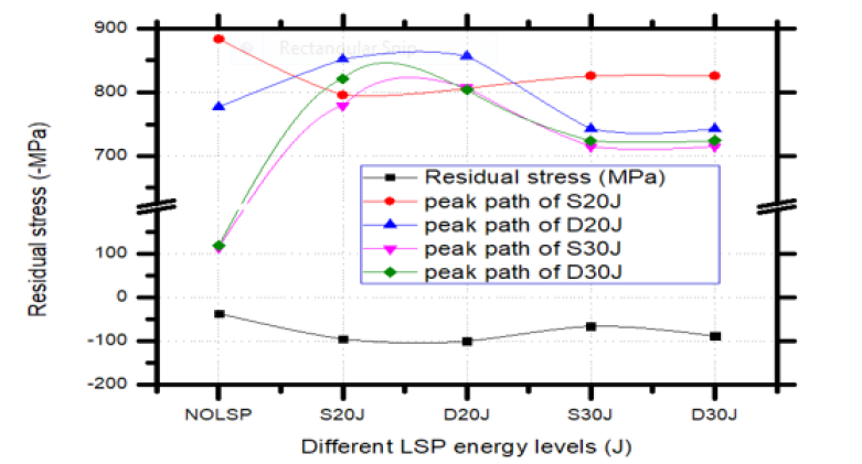
However, as we worked the outcome of residual stress revealed the distribution before and after LSP on the outer layer over the central-hole performance. This outcome results and distribution curve of the cross-correlation function with and without LSP were presented in Figure 3. It was real that residual stress probably generated during the machining and tooling processes of fabricating specimens distributed on the outer layer surface before LSP. This behavioral converted to fully compressive residual stress after the LSP process.
From Figure 4 the residual stress magnitude stepped up with the increase of LSP coverage area, when the NOLSP residual stress of 36.67MPa of a higher path of 763MPa from 1 to 3, increased its residual stress to 95.03 MPa after LSP of S20J specimen and further increased to 99.83 MPa after LSP both sides which are represented by D20J respectively.
However, from Figure 3b, the distribution track of crosssectional function peak value from the point of D20J, from 1 to 3, the peak residual stress increased from 777MPa to 852MPa, and this value gradually increased to 857MPa as the specimen subjected to a 3 paths LSP process. Again Figure 4 from the point of LSP of the energy of 30J pulse of single and double peened (S30J and D30J) the residual stress value of D30J was 88.11MPa is maximized than that of S30J of 65.33MPa value respectively. From Figure 3d from 1 to 3 of S30J, the peak residual stress increased from 114MPa to 779MPa and this value gradually increased to 808MPa as specimen subjected to 3 paths LSP process. It alarmed that induced outer layer surface peak compressive residual stresses were increased by 3 times in D20J and 2 times in D30J when the LSP path increased from 1-3 in both paths.
Figure 3: X-Ray diffraction analyzer distribution curve cross-correlation function and peak paths: a) NOLSP, b) D20J, c) S20J, d) S30J, and e) D30J.
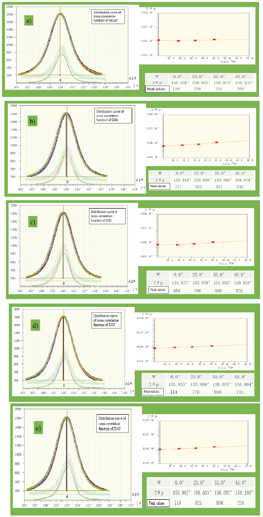
Figure 4: Residual stress analysis and different LSP energy levels.
Another point, in consideration of Figure 3a, 3c & 3e; from 3(a) from 1 to 4, the peak residual stress shut from 110MPa to 738MPa and the value drop to 731MPa and back to 763MPa. Like wised Figure 3c the peak value from 1 to 4 indicated a higher value of 884MPa from a start, decreased of peak value to 796MPa and increased to 806MPa and to 826MPa. From Figure 3e from 1 to 4 indicated that the second peak value was 821MPa as the higher and decreased to 804MPa and further decreased to 724MPa. Although capturing influences, there may be an exit some discrepancy between the proper values and the measured values due to the test approach. Despite that, the induced residual stress can also be found significantly increase under LSP scope and coverage area. However, the increment of outward layer surface compressive residual stress style of saturating as the LSP paths increased.
Fracture roughnessAlthough roughness influences the flow of oils in forming processes, having the proper roughness means having the proper oil contact. This makes an intricate distinction between elements able to make parts in mesh and catastrophe. On the aesthetic manner (appreciation of the beauty) side, roughness gives signer, either shiny or dull. The dull outward body layer over the entire treated outward body layer of the specimens’ metal plate was checked. The influence between the highest and lowest of the roughness of specimens was our ultimate investigation. From Figure 4, a result of the single-sided impact and single double-sided impact LSP specimens of S20J, S30J, D20J, and D30J and without LSP were analyzed. It was indicated that from the referenced of without LSP, the smoothness was 2.76 micrometer (μm), S20J (2.87μm), S30J (3.04μm), D20J (3.103μm) D30J (3.704) respectively. The outward layer texture of specimens D30J was 3.704μm and that of S30J (3.04μm) were quantified by deviations in the lay of the normal specimen without LSP of a real surface from its ideal form of without LSP 2.76μm, followed by D20J (3.10μm) and then S20J (2.87μm) respectively.
However, in rear nature, it is often necessary to pinpoint both the amplitude and frequency to ensure that a surface is fit for a purpose. Cheng et al. [13] emphasized on thermal technique on both LSP and WLSP with a subsequent post-shock contribution. Likewise, the differences in energy levels of shock. The fatigue life was delighted revolving stability of compressive residual stress and outer layer surface strength as sample D30J exhibited the highest. The roughness plays a significant occurrence in determining how an object of AHSS-DP 350/600 will interact with the environment of engineering. The specimen’s roughness outward body layer usually wears faster and quickly which have higher frictional coefficients than smooth specimens outward body layer of D30J (3.704μm), this may be a fine forecaster of the performance of a mechanical component of AHSS-DP 350/600.
For automotive industries and shipment materials, its higher roughness asymmetry on the outward body layer may form nucleation sites for cracks and corrosion when the force applied on to it such as specimen S20J with a result of 2.76μm respectively. For material-meal waste and degradations, surface factuality gives more meaningful predictions of mechanical forecasts of interactions at metal outward layer. However, contribute to decreasing the lifespan of the AHSSS-DP350/600/metal which is not our expectation. But resulted that the lower the energy level the higher smoothness and the higher the energy the higher the roughness level which is vice versa. Therefore, an object outward layer with a higher fractal dimension large value will usually have the influence of higher friction and wear to fatigue fracture (Figure 5).
Figure 5: Roughness test of single and double spot LSP result against different LSP pulse energy levels.

Fracture hardness
The rapture of AHSS-DP350/600 alarmed earlier on the outward body layer during manufacturing resistance of metal/ material to plastic deformation. However, temper resistance to scratching abrasion of metal that contributed to reverse a material from being deformed earlier when the foreign load is applied. The greater the metal hardness and reversed to the deformation. Therefore, the long span of AHSS-DP 350/600 specimen’s comforts ability, long life span after unique treatment was our optimal expectation. The experiment was performed on non-LSP and LSP treated specimens with different energy levels.
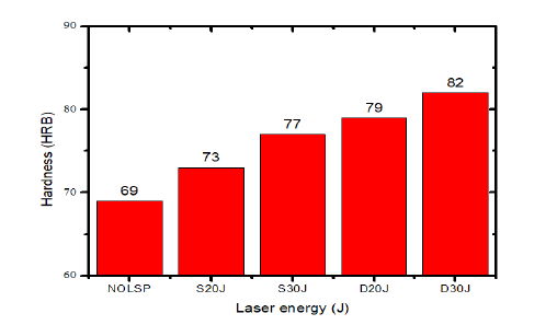
Figure 6 indicated results of specimens of NOLSP (69μm), S20J (73μm), S30J (77μm) D20J (79μm) and D30J (82μm) respectively. It revealed that D30J gave a higher result of 82μm and followed by D20J of 79μm, S30J of 77μm and without LSP specimen of 69μm respectively. Again, for the single pulse, specimens revealed that S20J gave a higher hardness result of 72.10μm, followed by S25J of 71.50μm, S30J of 70.0μm and non-LSP was 69μm respectively. This implied that LSP pulse with higher pressure plasma and its propagation contributed a lot to the unique arrangement of the atoms grain boundaries and increased. However, the positioned layer boundaries of grain and its arrangements star, the lighter the individual crystal grains, the harder the material becomes because metal material tends to deform at grain edges. Increasing the number of grain layer boundaries not only expanding the hardness but also makes it more brittle.
Figure 6: Single and double spot performance of LSP pulse on the hardness test against LSP pulse with different energy levels.
Analysis of fatigue experiment
The specimen’s non-LSP and LSP waves-irradiating were tested under the cycle loading and finally broke into two pieces, as shown in Figure 7 below. However, fatigue life davit as a result of both LSP and non-LSP of different energies in Figure 8. These results were compared to the fractured period and time of different shocking energy specimens as indicate in both Figure 8 & 9 respectively. However, Figure 8 indicated that the specimen without LSP had a fatigue cycle life to failure of 53562 as against those with LSP with different energies level and impact times of S20J, S30J, D20J and D30J also had fatigue cycle life to failure of 64201, 66143, 102076 and 102301 respectively. Montross et al. [14] investigated the influence of processing characterized and parameters analyzed on LSP shocking waves in conformity metal components. The LSP has great governed potential as a means of stepping up the mechanical characteristics performance of components which this cannot do without a selection of energy level on experimental based.
Figure 7: Images of material with and without LSP after fracture: a) NOLSP, b) S20J, c) S30J, d) D20J and e) D30J.

Figure 8: The fatigue life cycle of specimens subjected to different LSP processes.
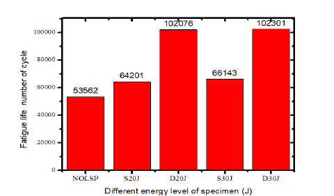
From Figure 9 it emphasized on cycle failure as against time of fractured that specimen without LSP used 17914 seconds for fracture whiles that of S20J, S30J, D20J, and D30J indicated 21403, 22056, 33876 and 34101 seconds respectively. It indicated a clearer difference of 16289 seconds between (D30J) 34101 seconds and (NOLSP) 17914 seconds. Again, Peyre et al. [15] shown in his paper that very small tiny outward layer gradients are found after LSP while Webster et al. [16] reported that residual stresses can have greater accordance with influence on the fatigue style of structural values of engineering components. However, Figure 8 & 9 were clearly shown that the higher dog bone LSP significantly fatigue cycle life was indicated by D30J and followed by D20J, S30J, S20J, and NOLSP. Therefore, specimen with the LSP indicates about 48739 fatigue life cycle increment as compared to without LSP before fractured comforted the above reports completely.
Figure 8: Different energies of LSP and time of fracture.

Again, it was noted that LSP specimens of D30J had a tramandouce improvement of cracks initiation at the surface and edges of the specimen followed by D20J, S30J, S20J, and NOLSP, however, the edges of the specimen with LSP were treated equally. Therefore, the location to minimum hardness level as evident on the micro harness and fatigue in Figures 6, 8 & 9 have revealed. However, this study revealed that hardening-strength introduced by LSP of energy(ies) were not the only suppressing of the crack propagation in peened fatigued specimens of which it supported views from some researchers, although it was postulated that crack closure was not the only cause for the crack growth retardation. The specimens LSP energies influence microstructure dynamic of closure as indicated, therefore the higher LSP energy the greater impact hardness on the specimen.
Fatigue fracture morphologiesDuring the accomplishment of admitting crack, under the cycle loading, all the period originates from the non-strong point of the specimens. LSP wave owns a very higher and powerfulness pulse width of 15ns dozen with spot square (4*4mm2) of nanoseconds generally course the solid particles to generate an intricateextremist strain rate under the conformity of LSP waves. The AHSS–DP 350/600 own conformity in mechanical and physical characteristics of martensitic and bainitic ferrite which increase the hardness and strengthen strictures of the specimen’s report confirmation.
The observation done on this paper revealed that FCG of AHSSDP 350/600 is seen in the center and the pre-crack at the edges of the shocked spot square specimens. This emotionally stirred governed affected shocked outward layer owns a sharp edges influence on earlier crack but due to the inner generated compressive stress reversed as vice versa. The fatigue striation links stepped up as crack path increasing and it initiated from crack grew conformity until failure. The then previous in conformity with fatigue-crack narrowed by LSP specimens as observed. This alarmed that fatigue striation was very large in LSP specimens which indicated that the crack distances were small. However, the smaller-tiny suppresses intricate effect on the material governed fatigue crack initiation and expansion from Figure 10 respectively.
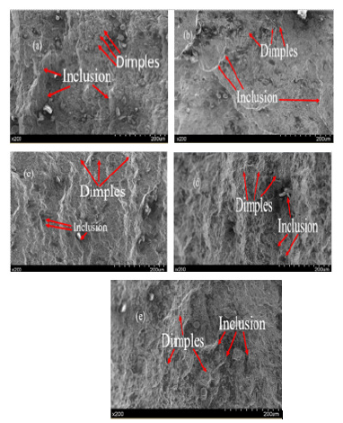
However, from Figure 10 again, the martensitic governed on the then stress intensity factor and metallurgical factors such as the higher stiffness/rigid and anti-intrusion. Therefore, the observation in Figure 11, that the overdue of stiffness by the energy level saw the ductility increases with strength and typically martensitic. Higher stiffness was accordance contributed factor of non-earlier cracks at the outward layer edges of the dog bone specimens during a fatigue cycle test. From Figure 12 cracks formed by crack sources and inclusions extend in radiation shape on LSP region and the FCG region. The fatigue fracture morphology had intricated obvious characteristics of dimples outward layer compressive residual stress in the surface layer of the LSP specimen’s offsets partial tensile stress. The secondary cracks engross large amounts of energy of fatigue crack extension, resistance was increased and FCG rate was effectively delayed by LSP specimens.
Figure 10: Morphologies of fatigue crack growth region on AHSS-DP 350/600 specimens: (a) Without LSP magnified image of (b), (c) S20J magnified of (d), (e) S30J magnified of (f), (g) D20J magnified of (h), (i) D30J magnified of (j).

Conclusion
The impact of LSP of different energies on AHSS-DP 350/600 specimens were investigated. The fatigue cycles, residual stress, morphologies, microhardness and roughness on the surface of the specimens treated and untreated were investigated. The fatigue fracture characteristic of AHSS-DP 350/600 specimens before and after LSP were discussed and analyzed:
A. Residual stress analysis of LSP can be seen that the induced outward layer peak compressive residual stresses are increased by 3 times in D20J and 2 times in D30J when the LSP paths increased from 1 to 2 to 3 in both paths. It indicated that shocking pulse of square sharp edge introduced tiny cracks on the outward layer which the wave’s inner compressive residual stress vice versa with enclosure significantly stepped up with enlargement of LSP coverage area.
B. Quality of the specimen’s surface treatment of different energies of LSP was all improved. However, the highest fatigue cycle life before fractured among the specimens was D30J as compared to NOLSP respectively. It was significantly indicated that clearer differences of 16289 seconds before failure as compared to without LSP respectfully.
C. The fatigue roughness of striation of the specimens of different energies with and without LSP revealed that the higher the energy levels the higher roughness and the lower the energy level the lower the smoothness of the surface of the specimens.
From the AHSS-DP350/600 specimens with different energies, there was collectively changed of fatigue crack initiation outward layer and the fatigue striation spacing with LSP. However, it’s an alarming fact that the totality of all the experiments and its observations done on LSP specimens in this paper on AHSSDP350/ 600 had a great influence as compared to without LSP significantly.
Figure 11: Fatigue fracture macrostructure morphology :( a) NOLSP, (b) S20J, (c) S30J, (d) D20J and (e) D30J.
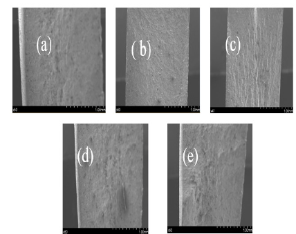
Figure 12: Morphologies of final fracture region on AHSS-DP 350/600 specimens: (a) NO LSP, (b) S20J, (c) S30J, (d) D20J, and (g) D30J.
References
- Cheng GG, Feng AX, Jiang YF, Lu JZ, Zhang L (2009) Effects of laser shock processing on mechanical properties of Fe-Ni alloy. Mater Des 30: 3673-3678.
- Banderas A, Gomez-Rosas G, Molpeceres C, Ocaña JL, Porro J, et al. (2006) Effect of an absorbent overlay on the residual stress field induced by laser shock processing on aluminium samples. Appl Surf Sci 252(18): 6201-6205.
- Guan HB, Lu JZ, Luo KY, Qian XM, Zhang LF, et al. (2010) The microstructure mechanism for mechanical property of LY2 aluminium alloy after laser shock processing. Mater Des 31(5): 2599-2603.
- Hill MR, Luong H (2008) The effects of laser peening on high-cycle fatigue in 7085-T7651 aluminium alloy. Materials Science and Engineering: A 477(1-2): 208-216.
- Curtis SA, De los Rios ER, Peyre P, Rodopoulos CA, Romero JS (2003) Effect of controlled shot peening and laser shock peening on the fatigue performance of 2024-T351 aluminium alloy. J Mater Eng Perform 12(4): 414-419.
- Berthe L, Peyre P, Scherpereel X (1998) Laser-shock processing of aluminium-coated 55C1 steel in water-confinement regime, characterization application to highcycle fatigue behavior. J Mater Sci 33(6): 1421-1429.
- Cui CY, Lu JZ, Luo KY, Zhang L, Zhong JW, et al. (2011) Effects of different shocked paths on fatigue property of 7050-T7451 aluminium alloy during two-sided laser shock processing. Mater Des 32(2): 480-486.
- Harris F, Hammersley G, Hackel LA (2000) Surface prestresing to improve fatigue strength of components by laser shot peening. Opt Lasers Eng 34(4-6): 327-337.
- Dai FZ, Ren XD, Ruan L, Sun GF, Yang HM, et al. (2013) The effects of residual stress on fatigue behavior and crack propagation from laser shock processing-worked hole. Mater Des 44: 149-154.
- http://www.autosteel.org
- Chen KM, Huang S, Lu JZ, Sheng J, Wang CD, et al. (2012) Effect of repeated impacts on mechanical properties and fatigue fracture morphologies of 6061-T6 aluminium subject to laser peening. Materials Science and Engineering: A 539: 360-368.
- Gu YY, Lu JZ, Luo KY, Sun GF, Zhang YK, et al. (2010) Grain refinement mechanism of multiple laser shock processing impacts on ANSI 304 stainless steel. Acta Metall 58(16): 5354-5362.
- Cheng GJ, Liao YL, Suslov S, Ye C (2012) The mechanisms of thermal engineered laser shock peening for enhanced fatigue performance. Acta Mater 60(13-14): 4997-5009.
- Graham C, Lin Y, Montross CS, Tao W, Yiu Wing M (2002) Laser shock processing and its effects on microstructure and properties of metal alloys: a review. International Journal of Fatigue 24(10): 1021-1036.
- Peyre P, Fabbro R, Merrien P, Lieurade HP (1996) Laser shock processing of aluminium alloys. Application to high cycle fatigue behaviour. Material Science and Engineering A 210(1-2): 102-113.
- Webster GA, Ezeilo AN (2001) Residual stress distribution and their influence on fatigue lifetimes. International Journal of Fatigue 23(Suppl 1): S375-S383.
© 2019 Baidoo Philip. This is an open access article distributed under the terms of the Creative Commons Attribution License , which permits unrestricted use, distribution, and build upon your work non-commercially.
 a Creative Commons Attribution 4.0 International License. Based on a work at www.crimsonpublishers.com.
Best viewed in


.jpg)


 Editorial Board Registrations
 Submit your Article
 Refer a Friend
 Advertise With Us
.jpg)


.jpg)


.bmp)
.jpg)
.png)
.jpg)


.jpg)


.png)

.png)


.png)


