- Submissions

Full Text
Research & Development in Material Science
Investigation on HSLA Steel Weld Metal; Heterogeneous Microstructures and Mechanical Properties: Propose to Modify Welding Procedure Specification
Dhruvi Patel1, Manjusha BS2 and Ketan K1*
1 Applied Chemistry Department, India
2 Department of Applied Science, India
*Corresponding author: Ketan K, Applied Chemistry Department, India
Submission: November 06, 2018; Published: November 30, 2018

ISSN: 2576-8840 Volume9 Issue2
Mini Review
Experiment and results. Single and multi- run HSLA steel welds were produced by MMAW process in flat and vertical up welding position. In this context, further work was carried out in parent plates 6.3, 8, 10 and 12.7mm thickness in bead on plate and Butt welds with E7018 LT and E 8018 (higher Ni content) electrodes. The microstructural study results in these welds are as follows: [1]. Flat welding position, 6.3 and 8mm thickness in bead on plate and Butt welds with lower heat input, fast cooling rates, shorter available time distance within initial austenitic temperature range, the weld microstructure consisted of pro eutectoid ferrite and inter granular acicular ferrite within pro eutectoid (prior) austenite grains. EPMA study revealed Mn and to some extend Si concentration were in their interface’s boundary region. The (segregated) alloying elements were not directly corresponding with each other’s. It shows that during pro eutectoid ferrite formation and its consequence growth, adjacent to prior austenite grain, Mn and possibly Carbon as an austenite stabilizer, have diffused out from newly formed pro eutectoid ferrite phase, they set up a diffusion profile with the rest of the proeutectoid austenite, surrounding the pro eutectoid grain interface. Furthermore, the intergranular acicular ferrite grain boundaries in proeutectoid austenite grains were covered with dark etching films (layer) constituents. Therefore; higher welding speed, lower heat input, specific high cooling rate could create proeutectoid austenite grains thermodynamically with new supersaturating condition, suitable for inter granular acicular ferrite formation within prior austenite grains with diffusion control solid phase transformation Figure 1.
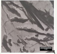
Single run vertical up welds 6.3 and 8mm thickness in bead on plate and Butt welds were prepared in the same parent plate and electrodes as in Item No.1 [2]. However; they had chemically lower concentration of alloying elements than those in Item welds. These welds with higher heat input, slower cooling rate and consequently longer available time distance within initial austenitic tempera ture range, the Initial austenite grains decomposed to other high temperature (Figure 2) dark etching microstructural constituent phase, i.e. lamellar type structural component. This could be due to the longer available time distance as well as suitable kinetic condition in initial austenite grains. Typical optical microscopy results revealed some pattern like the prior austenite grains with randomly dispersed ferrite grain, with no dark etching constituent’s films (layer) covered at their grain boundaries interface (Figure 3). EPMA study revealed there were random Mn distribution map throughout the matrix. There were some striations present in ferrite grains, which possibly could be formed by shear mechanism from the solidification and phase transformation state. The possible strain produced by the shear transformation activates many adjacent nuclei so that ferrite type plates form side by side type. The interior of some grains consisted of lamellar component type structure i.e. feathery bainitic lath structure forming side by side filling the interior of the grain (Figure 4). However, in some prior austenite grains there were also isolated dispersed fine ferrite type structure.
Figure 1:Tem extraction carbon Replica, Proeutectoid and Intergranular acicular ferrite weld Sample X1 (12.7mm).
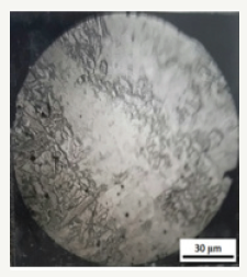
Figure 2:Tem extraction carbon replica, Intergranular acicular ferrite weld. Metal sample X1(12.7mm).
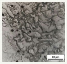
Figure 3:TEM extraction carbon replica, Intergranular acicular ferrite, microstructure of single run weld plate X1 (12.7mm).
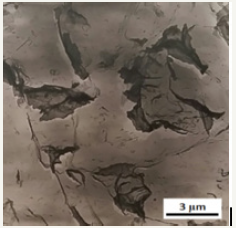
Figure 4:Tem extraction carbon replica, intergranular acicular ferrite, micro structure of single run weld plate X1 (12.7mm).
Single run weld microstructure-sample X (12.7mm thick plate). Microstructural studies revealed the proeutectoid ferrite grains were surrounding prior austenite grain. In some cases, dispersed ferrite grains were within pro-eutectoid ferrite region. The prior austenite grains interior had transformed to dark etching intergranular acicular ferrite. Direct extraction carbon replica (TEM) results revealed pro-eutectoid ferrite and intergranular acicular ferrite structure. The intergranular acicular ferrites were separated by grain boundaries which were covered by a cluster or film (partition) of a dark etching constituent (Table 1). EPMA studies revealed fine second phase particles (less than 1μm) consisting of different alloying elements. Thin foil study results by TEM study revealed various ferrite morphologies, some with high dislocation density, which were not necessarily within the ferrite grains but mostly in the grain boundary regions (Figure 5). The grain boundaries were free of particles; however, they were present within the ferrite grains. Single run weld microstructure, sample Y (12.7mm thick plate). Microstructural studies revealed a combination of aggregated fine interlocking ferrite grains, like intergranular ferrite and some coarser ferrite grains as well as side plate type microstructures [3].
Figure 5:Tem extraction carbon replica microstructure single run vertical-up, weld Y.
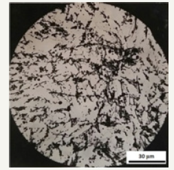
Table 1:

Direct extraction carbon replica results showed the presence of heterogeneous ferrite, some within the packets of coarser grains. Their grain boundaries did not appear as a continuous dark etching constituent film, but with dark etching constituent particles (possibly carbide). It appears that, at first the austenite transformed to disperse ferrite and then particles were precipitated on the available ferrite grain boundaries rather than distributing the same within the matrix grains. However; austenite did not transform to pro-eutectoid ferrite and intergranular acicular ferrite type structures like the weld X. Single run welds produced by E8o18 electrode (higher Ni content) revealed: In flat welding position, there were:
A. Dispersed pro eutectoid ferrite
B. Dark etching microstructural constituent with no clear ferrite grain boundaries in matrix
C. No intergranular acicular ferrite
D. With the nucleation of some fine recrystallized ferrite grains. Vertical up welding position, there were:
a. Dispersed dark etching component type micro structural feature,
b. Some feathery lath type structure.
In all these welds, in the last run fusion and heat affected zone interface the solidification is phenomenon of epitaxial growth structure (Figure 6). However, in previous weld run there was neither epitaxial growth nor typical refined grains structure which is defined by Dube classification and IIW modification. In the inter run layer, there were heterogeneous ferrite grains, internal defects, porosities, and precipitated micro alloying elements which are the cause of weld mental toughness deterioration (Figure 7). Therefore, this is essentially because of micro structural variation which is due to.
Figure 6:Tem extraction carbon replica, microstructure. Single run vertical-up weld Y.
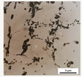
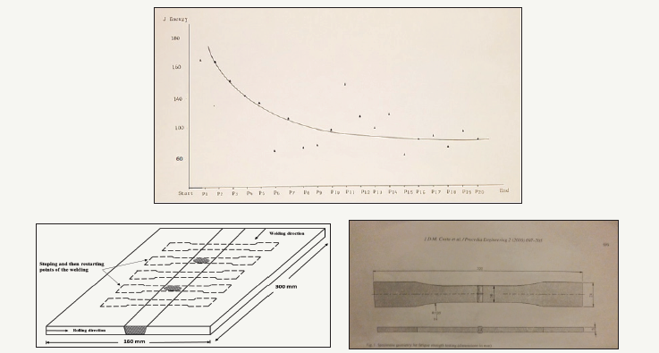
Figure 7:Different specimens impact energy(J) from plate p (vertical-up) welding position. Specimen p1 is from the starting (bottom) of the weld and p20 from the end (top) of the plate.
7a: Discontinuous welding, samples from stop/ start point in a welded plate (with Red color curve).
7b: Continuous welding plates (with blue color curve).
1. Applied thermal history and slower cooling rate,
2. Transmitted thermal stresses
3. Various weld dilution with parent plate and previous weld runs,
4. Inherited weld metallurgical characteristics from different rolling condition and parent plate specification. Thus, there is a need for re-evaluate
• HSLA steel multirun weld microstructure definition,
• Codes,
• Standards for tolerance acceptance for weld metal microstructural defects, their welding procedure specification (WPS) with a new comprehensive one for as-cast, inter-run region and previous weld runs microstructural feature.
Multirun weld metal mechanical properties were improved:
1. In Cu bead welded plates
2. Position those Charpy impact test specimens provided from start welded part have higher impact test energy value than those from middle and finishing (top) part of the welded plate in vertical up welding. The essential cause of toughness deterioration could be due to:
• Applied thermal history and slower cooling rate • Transmitted thermal stresses
• Various weld dilution with parent plate as well as previous weld run,
Inherited weld metallurgical characteristics from different rolling condition and parent plate specification (Figure 7a). Therefore; there is a need for re-evaluate the weld metal microstructural definition, codes and standards for tolerance acceptance of the weld metal microstructural defects. Their welding procedure specification with a new comprehensive one for as-cast, inter-run region and previous weld runs microstructural feature. Further research work results concerning HSLA steel weld metal with arc stop and start points welding condition and its fatigue test result are as follows: HSLA flat Butt weld metal was prepared by MMA Welding process in two different conditions:
Discontinues welding: welder will stop the arc at certain marked point and restarted the arc at the same point (Figure 7b). Continuous welding. Welder continues the arc without stopping it in the length of the plate. Before welding the plates were fixed in position by using welding fixtures. The parent plates were marked for showing the specific points that the welder should stop and restart the arc welding from that point.
After cutting the welded plates, the fatigue test specimen from those marked regions were specified as well. The welded joints were machined to a standard dimension for fatigue test specimens as shown below. The tensile and fatigue tests were carried out at room temperature by servo hydraulic Instron UK 8502. The fatigue test was carried out in uniaxial tensile-compression loading condition (R=-1) and a constant amplitude. This condition was used uniformly for all the specimens with the repeated loading direction which are parallel to the specimen axis. Fatigue experiments were conducted on 3 specimens at each stress level. The fatigue- tested specimens fractured surface were studied by using Scanning Electron Microscope (Philips, XL-30) at different magnification as well as in polished and etched specimens by Optical Microscope in order to analyzed fracture surface and possible microstructural variation in that region.
Conclusion
The mechanism of intergranular acicular ferrite formation in prior austenite grains is a diffusion control solid phase transformation. The Manganese and other austenite stabilizing alloying elements were depleted from the proeutectoid ferrite matrix and piled up on their proeutectoid ferrite-proeutectoid austenite grain boundaries interface. This is a stronger theory to contribute to increasing the nucleation chance of intergranular acicular ferrite, rather than acicular ferrite nucleation on oxide inclusions in all these welds.
In vertical up welding position, with lower welding speed, and consequent longer cooling rate time, and/or lack of Mn content, there is a chance for saturation and consequence formation of second phase (Precipitated) particles during longer available time distance up to real eutectoid transformation temperature for, depletion the metal matrix (austenite) solid solution from those alloying elements, and other solid state phase transformation. Therefore; higher temperature phase transformation products due to this delay time favoring formation of particles i.e. carbides, and different phase i.e. side plate, lamellar type structural component in HSLA steel weld metal.
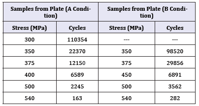
In low impact energy test specimens, there were some heterogeneous type microstructure in the inter run region with mixed equiaxed, elongated ferrite grains, segregated bands, accompanied array of inclusions and porosities with micro alloying elements precipitated particles (Table 2). They were not identified and classified by the welding procedure specifications and relevant acceptance criteria. Therefore; the WPS and PQR from the point of inter run region of multi run weld metal need to be revised and modify Figure 8.
Figure 8:Fatigue test results comparison, (stress vs. Cycle) for three specimens in each specific stress. Discontinuous welding, with red color curve, and continuous welding blue color curve.
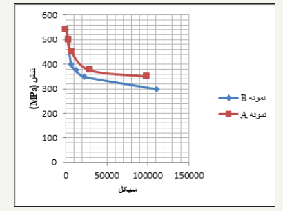
Table 2:Stress-cycle fatigue test results for different welded specimen conditions.
Further work.it is necessary to study, evaluate:
1. A new definition, guidelines, code and standards for different type of weld metals macro and micro structure for tolerance of acceptance of heterogeneous microstructure and imperfections present in previous runs and their inter run reheated region, as well as their effects on mechanical properties.
2. A new high strength welding consumables which meet the market requirements by Production of a new coated electrode and their associated welding procedure specification and procedure qualification records in order to prevent the entrapments of micro alloying elements in the precipitated particles, inclusions and second phase particles as well as aiming to control the type and tolerance of acceptance in weld metal heterogeneous microstructure , in their inter run and root run region.
To investigate the cause and condition for formation of intergranular ferrite with dark etching grain boundaries films and/ or dark etching ferrite grain boundaries precipitated particles in weld metals, it is necessary in certain welding condition to investigate the effect of alloying elements which are producing grain boundaries precipitated particles in conjunction with depletion of ferrite matrix from certain grain refining alloying elements.
References
- Hosseinioun MM, Moeini G (2016) Acicular ferrite nucleation as a diffusion-controlled process in high strength low alloyed (HSLA) steel weld metal. Materials Testing: 59(7-8): 661-672.
- Hosseinioun MM, Moeini G, Konke C (2017) An investigation on multirun metal made of HSLA steel-heterogeneous microstructures and mechanical properties: Propose to modify the welding procedure specification. RDMS 8(5): 1-2.
- (2018) 4th International conference on welding and failure analysis of engineering materials, Egypt.
© 2018 Mir Mostafa Hosseinioun. This is an open access article distributed under the terms of the Creative Commons Attribution License , which permits unrestricted use, distribution, and build upon your work non-commercially.
 a Creative Commons Attribution 4.0 International License. Based on a work at www.crimsonpublishers.com.
Best viewed in


.jpg)


 Editorial Board Registrations
 Submit your Article
 Refer a Friend
 Advertise With Us
.jpg)


.jpg)


.bmp)
.jpg)
.png)
.jpg)


.jpg)


.png)

.png)


.png)


