- Submissions

Full Text
Research & Development in Material Science
Additive Manufacturing by MMA Welding Process Characteristics and Microstructural, Mechanical Properties: Propose to Modify the Welding Procedure Specification
Mir Mostafa Hosseinioun *, Ghazal Moeini and CarstenKonke2
1Department of Marine Engineering, Amirkabir University of Technology, Iran
2Department of Marine Engineering, Bauhaus University Weimar, Iran
*Corresponding author: Mir Mostafa Hosseinioun, Department of Marine Engineering, Amirkabir University of Technology, Tehran, Iran
Submission: October 10, 2017; Published: February 20, 2018

ISSN: 2576-8840Volume3 Issue4
Abstract
In this investigation, high strength low alloy (HSLA) steel plates, welded by Manual Metal Arc (MMA) process. The microstructure was studied accompanied with its effect on the mechanical properties. Microstructural features in each weld run as well as inter run region of the multi run weld metal were studied and the essential cause of deteriorated weld metal toughness were explained. The micro structural studies revealed:
1. Inter granular acicular and pro-eutectoid ferrite in the as cast last run
2. Refined grains in previous runs
3. Some heterogeneous ferrite grains as well as internal defects, porosities, and precipitated micro alloying elements in the inter-layer region with previous runs.
In the last run fusion and heat affected zones interface the solidification is phenomenon of epitaxial growth structure. However, in previous weld run there was neither epitaxial growth nor typical refined grains structure which is defined by Dube classification and IIW modification. The weld metal mechanical properties were varied in different parts of the welded plate due to the weld dilution with parent plate and inherited weld metallurgical characteristics in comparison with those from HSLA steel plate.
Therefore; there is a need for re-evaluate the codes and standards for definition and tolerance acceptance of the weld metal microstructural defects with comprehensive one in the as-cast structure, inter-run region and previous runs as well as their welding procedure specification.
Keywords: HSLA steel; Weld metal mechanical properties;Microstructural defects
Introduction
Steel industry within certain manufacturing procedure under definite planed control are producing flawless, homogeneous, fine and ultra-fine acicular ferrite grains which is known as HSLA steels, but not specifically HSLA weld metal [1-8]. This defined procedure is controlling the time, temperature, strain rate, thermal cycles, and deformation, rolling conditions, austenite grain size, recrystallization, grain growth, recovery and steel solid phase transformation. The HSLA steels have certain specifications, such as steel chemistry, rolling and cooling parameters, micro structure and its associated mechanical properties as well as considering satisfy processing requirements such as weldability, machinability, formability, and recyclability and corrosions resistance. Therefore, they can produce deformed plates consisting homogenous acicular ferrite with completely different procedures from intergranular acicular ferrite and refined ferrite grains in the weld metal which produced in various welding conditions and. heat inputs [9-12]. The HSLA steels mechanical properties requirements i.e. toughness and fatigue strength have been relatively easy to achieve. However, the multi run weld metal mechanical properties requirement i.e. toughness and fatigue strength in welded structure produced in different welding condition which is known as special process is more problematic [13-15]. Research work to improve safety of the structures of HSLA steels resulted in production of fine acicular ferrite grains under the
(i) Oxidation, de-oxidation processes
(ii) Specific solidification modes
(iii) The presence of proper amount of alloying elements
(iv) Certain final chemical compositions
(v) Hot and cold controlled rolled operations
(vi) Suitable thermo-mechanical treatments
(vii) Controlled solid phase transformation
(viii) Specific precipitation, aging processes in conjunction with solid phase transformation (specific precipitation and aging processes).
However, different thermal cycle heating (heat treatment) for this steel plate or pipe is obviously not recommended. Furthermore, the primary grain refinement mechanism in controlled roll steel is recrystallization of austenite during deformation as well as steel chemistry and cooling parameters. The next stage grain refinement is enhanced through a combination of controlled rolling parameters, such as:
i) Reheating temperature, percentage of reduction, deforming temperature, inter pass temperature
ii) Cooling conditions (such as heating and cooling rate, as well as plate finished cooling temperature)
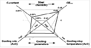
iii) iii) The influence of micro alloying elements and Carbon equivalent content with these controlled rolling working conditions in industry as shown in Figure 1.
Figure 1: Different approaches to reach the strength level of X100 by varying steel chemistry, carbon content, (Ceq) and cooling parameters.
In addition; the other important parameters are such as:
a. Optimum reheating temperature which could lead to the best possible initial austenite grain size, this is starting point for further control of the mechanical properties during the rolling process.
b. Maximum possible deformation ratio during the first rolling stage for the first grain refinement of recrystallized austenite.
c. The finished rolling temperature as close as possible to the Ar3 transition point for a proper control of pancaking of the non-recrystallized austenite with high dislocation density.
d. Transformation into fine grained lower bainite after accelerated cooling i.e. a cooling rate of above 20k/s and a cooling stop temperature below 400 °C are the main process parameters.
This is the procedure to produce controlled roll steel with fine granular ferrite and a hard phase mainly composed of bainite by optimum TMCP conditions with a high strength, large uniform elongation and good low temperature toughness. In comparison with the restricted above mentioned rolled steel production procedure, the desire weld metal metallurgical characteristic and properties cannot be performed properly by using WPS and PQR in MMA welding process in order to modify and optimize it by complicated welding variables.
Therefore; the above mentioned procedure in rolled steel neither have been considered nor were under controlled for each weld run in multi-run MMA welding process. Generally, in multi-run welding due to induced high temperature gradient, and cooling rates as well as non-equilibrium phase transformation, the microstructure is locally destroyed and the mechanical properties are deteriorating. Therefore, it is essential to quantify each weld run and inter run weld individual constitution, and its micro structures, which are influencing the final mechanical properties of multi run weld metal [16-21].
In Dube classification, there are three main constituents, namely allotriomorphic ferrite, intergranular and side plate ferrite for microstructural studies in wrought steel with controlled production procedure in steel industries. However; the number of constituents are too limited to describe fully allotriomorphic structure or to distinguish primary and secondary side plates, lamellar type structure, reheated bead and partially re-crystallized structure which are present in multi run weld metals [22-24]. In addition to Dube classification which belongs to years ago, recently Thewlis G [25] has been performed in depth investigation to cover and explain a classification and qualification of microstructures in steel. He has used IIW microstructure classification as a basis for recognizing complex microstructures for welded zones. These definition and classification of wrought steel structure are traditionally used for different weld metals produced by various welding process and variables for the as cast structure as well as those reheated regions in inter-run and refined previous runs with the heterogeneous micro structure which have different degree of dilution, recrystallization, refinements and aging characteristics.
The weld metal micro structural development is depending on the solidification and consequent solid phase transformation of the weld pool. The principles of solidification control the size and shape of the grains, segregation and the distribution of inclusions, porosities, defects and solid phase transformation products which control the final weldment microstructure and mechanical properties [26-32].
In steel casting solidification mechanism, the solid crystals from the melt require heterogeneous nucleation of solid particles, principally on the mould walls followed by grain growth [33-35]. In comparison, among all weld metal solidification parameters, growth rate, temperature gradient, undercooling and alloy compositions are playing major roles in microstructure of the fusion zone. In the weld pool these parameters are varying considerable in the as cast structure and inter run region structure. The weld pool solidification and microstructural development are based on these parameters which are explained in the literature [36-37]. Each run in multirun weld metal shows different types of microstructure. They consist of, as cast and partially refined grains diluted with parent plate and previous runs as well as solid phase transformation, recrystallization and recovered refined microstructure.
These micro structure and consequently its quality depends on the welding parameters i.e. heat input, cooling rate, dilution and degree of recrystallization. The solidification and phase transformation under the effect of arc movement, stirring, electromagnetic Lorentz forces and solute redistribution in inter runs and consequent changes in chemical compositions. Comparing the production process procedure in steel industry and welding procedure specification, it revealed that refined intergranular acicular ferrite type micro-structure in as cast last run weld metal and refined grains in the previous root runs are completely different from the acicular ferrite refined grain type microstructure in controlled rolled steel plate.
In addition, comparison welding with casting processes revealed, since solidification of the weld metal starts from absence of the mould wall, the solidification proceeds spontaneously start with no nucleation barrier by epitaxial growth of the partially melted base metal grains as well as the as cast structure of first run (previous). The nucleation process in such a weld is eliminated during the initial stages of solidification, because of the mechanism of epitaxial growth, wherein atoms from the molten weld pool rapidly deposited on pre-existing lattice sites in the adjacent solid base metal. Therefore; in a single run and last run weld metal, the structural characteristics of the grains in fusion zone interface are mainly determined by as received rolled base metal. whilst, in multi run weld, each weld run grain structural characteristics are mainly determined by its previous weld deposited grains structure, which had been produced with various metallurgical characteristics, in certain welding conditions, chemical compositions and solid phase transformations, heating and aging processes [32,33].
Crystallographic effects will influence grain growth by favouring growth along particular directions (<100> for cubic metals). Weld rapid solidification interactions with heat source conditions will provide optimum growth conditions when one of the easy growth directions coincides with the heat-flow direction in the weld metal. Thus, among the randomly oriented grains in a polycrystalline specimen, grains with <100> crystallographic axes closely aligned with heat-flow directions are desirable. However; without additional nucleation, this will promote a columnar grain structures. Under certain conditions it is also possible to change the epitaxial columnar growth to equiaxed growth by inoculation or changing welding conditions [34-37].
Therefore; the single and multi-run weld metal microstructure are also predominantly controlled by the heat source, inherited parent plate and previous weld run structural characteristics, crystallographic orientations as well as parent plate annealing twins. This process generates weld metal grains in the same crystallographic orientation as the immediately contiguous parent plate grains across the fusion zone/heat affected zone interface.
However; in multi-run weld i.e. in each consequences runs, the lower part of its initial weld runs, with the originally as cast structure has been heat treated and transformed to partially recrystallized, refined grains and some porosities, also it might be associated with dislocations pile up, second phase particles and aging which cannot be predicted or evaluated by the existing WPS and PQR requirements.
Weld quality. Each weld run experienced various cooling rates, solid phase transformation, and different degree of recrystallization, recovery, solid solution, hardening and aging, which are different from rolled steel parent plate production procedure but not in metallurgical (microstructural) defects. Weld discontinuities (mechanical defects). The various weld metal physical, mechanical defects and their quality level for imperfections are defined and designated as physical, internal and external in steel industry.
Many codes and standards for weld quality level of imperfections in shop fabrications are explained in old German DIN8563, British BS PD 6493 (later BS 7910), ISO5817, ISO 6520 in respect to the weld quality and mechanical properties. Typical of known common weld metal surface imperfections (discontinuities) were classified recently as ISO. Doc. DTS 20273: 'the relationship between weld quality and fatigue strength' (to complement ISO 5817).
The mechanical properties, such as yield and tensile strength, module of elasticity and fatigue strength are depending on the micro structural parameters. However; the above mentioned standards are based upon workmanship criteria, as well as uniform type of microstructure but not considering the different metallurgical features i.e. weld metal heterogeneous microstructure, for evaluation and prediction of the weld metal properties. Therefore; the microstructural inhomogeneity’s which are present in the bead interior of the reheated region in multi run weld metal are not included in these codes and standards.
In addition, the tolerance of acceptance of microstructural constitution ofweld metal, dilution with parent plate, the consequent change resulted in chemical compositions and microstructure, the thickness of each layer and inter layer, as well as degree of solid solution, precipitation hardening and aging re-crystallized, refined structure and porosities are not defined by the welding procedure specification (WPS), procedure qualification record (PQR) and IIW guide lines. Therefore, it is necessary to make additional revision to the current standards about definition of MMA multi run weld metal microstructure, and /or in a newly comprehensive revised microstructural defects (not only mechanical defects) code and standard.
In this investigation HSLA steel plates specified Y with 12.7mm thickness, were multi run welded by MMAW process. Experimental work has been carried out in both down hand (flat) and vertical up welding positions to find specific relation between microstructure and mechanical properties of the joint. It appears that improving the welding procedure specification (WPS) and procedure qualification record (PQR) are needed to be defined and develop.
Experimental Procedure
Table 1: Chemical composition of electrode wire (wt%).

Table 2: Welding condition for multi-run butt welds.

Table 3:

1VU: Vertical up
2DH: down hand
3Plates R and S were prepared in the down hand welding position on a copper based plate.
The MMA welding technique is used to produce 8 different butt weld joints with E7018LT AWS electrode. Electrodes were preheated for at least one hour at 250 °C and inter pass temperature was considered 170 °C. Typical electrode wire is given in Table 1. Weld metals were made according to ISO 2560. Multi run welding conditions are shown in Table 2. The simple Y butt joint design with 60° angle was used. Labelling of the plates and welding positions are shown in Table 3. Special care was considered to allow the temperature of the plates fall down to approximately 170 °C before starting the next pass. Each experiment plates and weld specimens were prepared after cross section cutting of the welded zone.
Chemical composition analysis was carried out from parent plate X and Y as well as different weld metals. In addition, chemical analysis for Mn, Si, O and C were carried out on some drilled specimens as shown in Tables 4 & 5.
Table 4: Chemical composition (wt%) of single, triple run weld and parent plate X, Y (12.7mm).
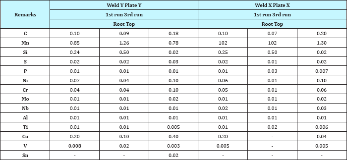
Table 5: Chemical composition (wt%) multi-run weld metals, and plate Y (12.7mm thick), vertical-up and flat welding (wt%).

Metallography
Optical microscopy (OM) was performed on the weld metal specimens. Transmission electron microscopy (TEM) was carried out on the samples by using an accelerating potential of 80KV for carbon replicas and 100 KV for thin foil study. The samples were taken from the cross-sections, top surfaces and adjacent to the fracture path in tensile, charpy impact and fatigue test specimens. Direct carbon replicas were produced to clarify the features of the optical microscopy results. It has been possible to add the information derived from both thin foil technique and extraction carbon replicas to optical microstructural results.
The fracture surfaces were examined by means of the SEM using 25KV accelerating voltage and 35° tilt, and then specimens were studied optically and by TEM. Electron probe microanalysis (EPMA) was used to investigate any possible segregation of certain alloying elements e.g. Mn and Si, in different weld metal area, i.e. intergranular ferrite and pro-eutectoid ferrite as well as inclusions and second phase particles chemistry.
In this context extensive metallographic examinations were carried out by using mean linear intercept measurement with test patterns of either circular or straight parallel lines for quantitative metallography. The circular pattern consists of three concentric and equally spaced circles with total circumference of 500mm. These patterns were used for measuring the width of the equiaxed and elongated grains respectively. The patterns were successively applied to five randomly selected spaces fields. Low (x60) and high (x1500) magnification examinations were carried out in order to assess the prior austenite grains.
High magnification (x1000) examination was carried out for measurement of each weld interrun and the re-crystallized refined grain size in multi-run weld metals. Quantitative data on the proportion of different micro structural constituents in the weld metal microstructure were produced by using a swift point counter. The data was obtained by counting 1000 points in each reading.
Results
Macrostructure
Macro-structural studies for different welds revealed the presence of various solidification substructures with the presence of solute bands, with alternate light and dark etching bands or contours show the variations of solute content and consisting of solute enrichment due to a sudden increase of growth rate. Some weld metals exhibited disoriented dark etching columnar grains located along the weld axis. There were also some cases where the columnar grains established near the fusion boundaries grow continuously to the centre of the weld metal. Based on solidification mode, heat extraction direction, cooling rates, and variation in solute content and growth rate, they could lead to the formation of various solidification sub-structures in each run consist of equiaxed and elongated dendrite type structure, consequently, solid phase transformation austenite to ferrite lead to form different weld metal micro structures and their associated mechanical properties.
Figure 2: The fractured path throws solidification sub-struc-ture layer in broken impact test specimen with 217 J im-pact energy (enlarged in reprinting).
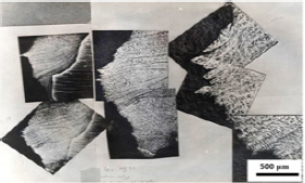
Figure 3: Fractured path throw solidification sub structure a. Layer in broken impact test specimen P2 b. Multi-layer weld in broken impact test specimen P21
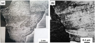
Typical weld metal solidification sub-structure from broken impact test specimen is shown in Figure 2. The fractured path follows the minor ripple bands in the direction of the macro solidification sub-structure layer in each weld run through the direction of the macro-solidification pattern as shown in Figures 3a & 3b.
In addition to the presence of solute bands in multi run weld metal, they revealed how the fracture path has propagated and changed directions in transverse cross section area through elongated dendrite from each weld run.
Microstructure
In this investigation micro structural studies were carried out in tensile, impact and fatigue test specimens from multi run weld metals. Due to the removal of most part of the first and last run welds surface during sample preparation by machining, more attention has been paid to the third run weld metal micro structure and their interface with other weld runs which were around the V notch in impact, as well as surface area of tensile and fatigue test specimens, the result revealed three main following microstructural categories:
Last run as cast structure
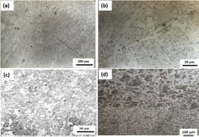
Figure 4a: Weld metal heat affected zone interface (epitaxial growth) 4b: optical micro structure multi run weld metal, specimen no.4, Plate J last run
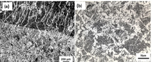
The micro structural studies in the fusion zone and parent plate HAZ interface revealed the presence of epitaxial growth type structure which is shown in Figure 4a. In the top surface last run with the equiaxed macro solidification sub-structure the micro structure is consisted of equiaxed pro-eutectoid ferrite and inter granular acicular ferrite as shown in Figure 4b.
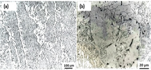
In transverse cross section with the elongated macro solidification sub-structure area there were various proportion of different micro structural constituents present, i.e. some elongated pro-eutectoid ferrite type optical micrographs are depicted on Figure 5a as well as precipitated particles are shown in Figure 5b.
Figure 5a: M2 Last run sample no.2.
5b: last run impact test specimen
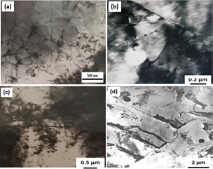
Furthermore, micro structural studies in the last run welds with Optical Microscopy and Direct Extraction Carbon Replicas revealed typical of inter granular acicular ferrite and pro-eutectoid ferrite as well as (blocky phase) grains surrounded by a dark etching constituent. Inclusions with their certain chemical composition were distributed randomly in both pro-eutectoid ferrite and inter granular acicular ferrite type's micro structure and no evidence of inclusion separation was observed due to their particular composition. Therefore, they were not necessarily associated with specific phase i.e. proeutectoid and/or inter granular acicular ferrite or even lamellar (side plate) type structure. TEM extraction Carbon replica and thin foil studies show more dislocated granular ferrite grains and some dark etching constituents as shown in Figures 6a-6d.
Figure 6: TEM, thin foils microstructure from wed metal,
6a: Last run near the notch region no. J4
6b: Third run near the notch specimen F5
6c: Inter run below notch region sample P18
6d: TEM extraction carbon replica, microstructure of the last run weld metal, below the notch inter run region P8.
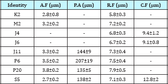
The mean linear intercept measurement quantitative metallographic results for some welds obtained from last run with the as cast structure and first run refined ferrite grains were listed in Table 6. For the last run it shows about 70% acicular ferrite with grain size content from 2.7±0.2μm to 3.8±0.2μm with the average 3.2μm accompanied with theprior austenite grain size averageof 156±2.3μm (Table 6).
Table 6: Quantitative metallography from multi-run weld metals. Mean linear intercept and 95% confidence limits values given in pm.
Inter run region
In this region, interface between two welds layer were not similar to the epitaxial growth phenomenon as shown in Figure 4a. They were consisted of different micro structural constituent; some of them were not aligned with each other's such as:
Discontinuous coarse prior austenite grains growing within the previous cast structure as depicted in Figures 7a-7c. There was heterogeneous type structure consisted of coarse and recrystallized grains with some fine particles as shown in Figure 7d.
Figure 7: As cast structure
7a: With internal defects, inter-run region last run interface sample P9
7b: With internal defects (surface fissure) specimen P21
7c: Typical optical micrographs as cast structure inter run region.
7d: Recrystallized inter run region last run interface.
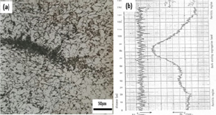
Macro segregation bands possibly due to sudden change in the welding parameters and the resultant change in growth velocity were also present in the inter run region. The line scan data across these dark etching bands revealed the presence of high Manganese concentrations, whilst Silicon diffused evenly without any regional homogeneity. However, no Sulphur was detected associated with this Manganese segregation bands, this can be observed in Figures 8a-8b. The hardness of these segregation bands in different specimens varied between 310-380 VPN.
Figure 8: Segregation in inter run recrystallized region specimen M2
8b: Typical line scan electron probe micro analysis for Mn and Si across the dark etching segregation band specimen M2 respectively.
Micro structural study result of different weld specimens with low impact energy (less than 60 Joule at -20 °C) and low fatigue strength revealed that, there were some dispersed dark etching constituents in the ferrite matrix with blocky type ferrite structure accompanied with fine precipitated particles as shown in Figures 9a-9c.
Figure 9: TEM extraction Carbon Replica, second run (inter run) micro structure at -20 °C
9a,9b: Specimen with low impact energy (H11. 57 J)
9c: Specimen H10 with 45 Joule energy
9d: no.4, third run plate M1 with 138 Joule
9e: no. P1, plate P below the notch region, with 165 Joule
energy.
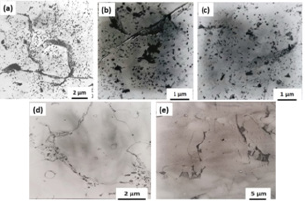
However; typical Extraction Carbon Replicas micrograph of weld metal microstructure with high impact energy ((i.e. more than130 Joule at -20 °C) are depicted in Figures 9d-9e.They have no dark etching constituent's ferrite grain boundaries film in comparison with those shown in Figures 9a-9c.
Furthermore, in this weld metal region macro structural studies revealed they have cellular solidification sub-structures and less dilution with parent plate in the previous or next runs (thinner inter-run region).
Refined region
Figure 10: Optical micro structure multi run weld metal
(flat weld), specimen J4
10a: First run
10b: Inter run region.
10c: TEM extraction carbon replica, microstructure of first run weld metal specimen S7 with high impact energy 217 Joule at -20 °C.
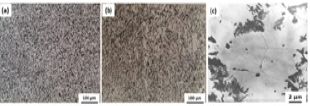
Typical weld metal microstructure in first root run with refined ferrite grain size about seven microns with well-defined type fine grain micro structure which were depicted in Figure 10a. However; in comparison there was some inconsistency in grain size measurement in some welds due to the presence of heterogeneous fine and coarse grains microstructure as shown in Figure 10b.
Figure 11:
11a: Optical micrograph multi run weld metal, first run, specimen E5 recrystallized region with voids formation (in-ternal defects)
11b: Polished11c: SEM micro graph surface multi run weld metal recrys-tallized region with voids formation (internal defects).

Typical Extraction Carbon Replicas micrograph of weld metal with high impact energy (217 Joule at -20 °C) consisted with smaller and more equiaxed refined grains as depicted in Figure 10c. However, in some specimens there was some porosity which might demonstrate the remainder (residue) of cluster of unexpected oxide particles in the first run refined grains which were not present in the weld metal as cast structure, and inter run regions as shown in Figure 11a. SEM micro structural study of the first run weld metal in both as polished and etched conditions revealed some of them as shown in Figures 11b-11c.
Figure 12: TEM extraction carbon replica, weld metal microstructure specimen k5
12a: Inter run (second run) region
12b: Third run region
12c: Thin foil wed metal micrograph from J4 Last run near
the notch region
12d: First run specimen J4
12e: TEM thin foils micrograph with precipitated particles, Specimen P18 third run region.
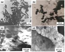
TEM thin foil study by window technique from different welds with low impact energy revealed the presence of various microstructural features such as fine precipitated particles within the heavily dislocated ferrite grains as shown in Figures 12a-12d.
Electron diffraction patterns revealed the presence of low angle grain boundaries which are not generally as effective crack arresters.
Figure 13: Weld metal microstructure of crack propagation in last run as cast structure unbroken tensile test specimen J4. unbroken tensile test specimen refined region crack propagation.

Micro structural study of nickel plated multi run weld unbroken tensile test specimens revealed the presence of micro cracks mostly at the grain boundaries as well as in the pro-eutectoid ferrite region along the common interface with prior austenite grains. The micro cracks separation was not usually within the ferrite grains matrix. After the onset of necking, the crack extended into cavities followed by coalescing leads to final separation as shown in Figure 13. Similarly, micro structural studies of fatigue tested weld metal specimens revealed presence of micro cracks at the interface of grain boundaries as depicted in Figures 14a-14c.
Figure 14:
14a,14b: Micro structure weld metal fatigue specimen fractured surface with surface tearing and fissures
14c: As polished sample.

Figure 15: Typical SEM-MPA micrographs,
15a: Different second phase particles weld metal no. P15
15b: Associated carbon distribution map, different second phase particles weld metal no. P15
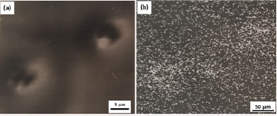
SEM-MPA micrographs, of carbon distribution map and EDAX prints from different second phase particles from weld metal specimenno. P15 with low impact energy are shown in Figures 15a-15b respectively. Considering certain amount of austenite and ferrite stabilizing alloying elements are available in solid solution and/or in second phase particles Therefore; The carbon entrapment particles could deplete the metal matrix from such a strong austenite stabilizing alloying element in the presence of ferrite former elements in solid solution, promoting earlier decomposition of austenite, due to provided suitable kinetic condition for proeutectoidferrite formation. Microstructural study in transverse cross-section in that specimen revealed that both equiaxed and needle type ferrite grains were present.
The relative proportion of acicular ferrite in the last run sample with low impact energy (60 Joule at -20 °C) is 14%, whilst the proportion of the coarse ferrite grains is 68%. However, there were region of the coarse ferrite grains with randomly distributed pockets of inter granular acicular ferrite within the prior austenite grains. The prior austenite grain sizes in last run multi run welds are generally larger than single run welds , their value for multi run weld produced in down hand and vertical-up welding position, were 138±2 and 207±19 microns respectively.
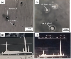
SEM-EPMA studies have been carried out for multi run weld metals; the result revealed coarse and fine particles, consisting of different alloying elements in all type of microstructures. Typical related micrograph and EDAX analyses are shown in Figures 16a-16d. Apart from the fine slag inclusions in these weld metals, there were particles consisting of Fe, Mn and Ti accompanied with the porosities.
Figure 16:
16a,16b: Typical SEM - MPA micrograph of second phase particles specimen P15
16c, 16d: Typical EDX print from second phase particles specimen P6.
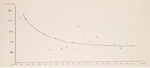
Mechanical Testing; Impact test weld metal specimens from each welded plate were tested at -20 °C, 0 °C and +20 °C. In addition, twenty weld metal impact test specimens from plate P prepared in vertical up welding position were tested only at -20 °C. Specimens from plate P were cut and marked as number one to twenty from welding start point at the bottom of the plate toward the end of the plate to the weld finishing point in the upper part of the vertical up welding position respectively. The impact test results from plate P are shown in Figure 17.
Impact test specimens from plate P had more scattered impact energy value than the rest of the welded plates. Impact test specimens from the start welding position in plate P had higher impact energy value than those obtained from the finishing part (top) the welded plate. Impact test specimens from weld metal plates S and R (prepared in down hand welding position on a copper bead position) had the highest impact energy values in comparison with the rest of the welded plates.
Figure 17: Impact energy of different specimens from plate p (vertical-up) position, specimen p1 is from the starting (bottom) of the weld and p20 from the end (top) of the plate.
The outcome of this experimental work is in agreement with the results of other researchers [38-41] which have suggested that addition of alloying elements such as Manganese and increasing the cooling rate resulted in prevention of formation of heterogeneous ferrite grains in inter runs and refined grain in the previous weld runs.
Discussion
For production of HSLA steel, conventional and controlled rolling operations are used within certain restricted manufacturing conditions. In this context the main strengthening mechanisms include:
(i) Dislocation strengthening
(ii) Grain boundary strengthening
(iii) Solid solution strengthening
(iv) Precipitation (particle) strengthening - second phase particles may be dispersed (stable particles mechanically added and then sintered) or precipitates (particles formed from supersaturated solid solution). The latter type is more present in practice. The limitation of this mechanism is governed by the influence of the particles size and shape, on the toughness value, instead of the strength.
(v) Texture strengthening-the resistance to dislocation movement due to the presence of texture and preferred orientation in structure.
(vi) Phase transformation strengthening-the resistance to dislocation movement due to the presence of newly formed phases introduced by the solid phase transformation which starts simultaneously with deformation.
This mechanism gives new opportunities for research challenges of steel and weld metal in the near future. Comparing such a controlled industrial working conditions and procedure in steel production, with multi-run weld metal production revealed that such a controlled variable in steel industries neither have been considered nor have been under control in welding for each weld run. It is common to consider the multi run weld metal microstructure as acicular ferrite in last run and refined grains in previous runs as a preferred micro structural feature from the point of their improved mechanical properties. However; due to variation of welding parameters and heating cycles during multi run welding, the micro structure could be deteriorated and lead to poor mechanical properties. Weld metal grain structure is predominantly controlled by welding parameters and the base metal characteristic. In multi run welding each new weld run is expected to re-crystallize inter pass (HAZ) layer as well as previous runs in to fine grain structure. The inter pass layer is heated up to austenitic region but not possibly the best initial austenite grain size which is necessary for the starting point for further control of the microstructure and its associated mechanical properties as a result of solid phase transformation. Furthermore, the grain growth rate in newly formed grains may take place, depending on the
(i) Weld heating rate
(ii) Peak austenite temperature
(iii) The residence time at that peak temperature
(iv) The weld cooling rate i.e.as the cooling rate decreases, the residence time increases, substantially coarsening grain size could occur.
Therefore; each multi run weld will have produced grains with different micro structural constituents. I.e. reducing the heat input in each run could lead to minimization of the softening of the well- meant in combination with an improvement of its toughness.
In addition Babu [42], in his investigation concerning classification and quantification of microstructures in steels, did not explain clearly about acicular ferrite and its formation mechanism in multi run weld deposit. This could be due to the metallurgical characteristics of the previous weld runs, as well as variation of welding parameters and thermal cycles particularly in the inter-run of previous weld runs, as well as variations in chemical compositions, degree of stiffness, restraining conditions, different degree of recrystallization and grain refinement of prior austenite grain size in weld metal in comparison with various production procedures and inherited physical and metallurgical characteristics of HSLA parent plate. In another author's research work results [43] concerning microstructural studies of single run flat and vertical up welds in different thick HSLA steel plates following results were revealed: The as cast microstructure in 6.3mm thick plate in flat welds were consisted of pro-eutectoid ferrite and intergranular acicular ferrite within prior austenite grains.
a. In the as cast microstructure single run vertical up welds the microstructure showed dispersed ferrite grains and some lamellar type structural feature accompanied with striations, in addition inside some grains, there was also feathery side by side lath type microstructure present.
b. In single run weld vertical up position in 12.7mm thick plate, based on the amount of manganese content, pro eutectoid, intergranular ferrite and fine/coarse interlocking side plate ferrite structure can be detected. Furthermore, in austenite transformation to pro-eutectoid and acicular ferrite structure, manganese as an austenite stabilizer alloying element is playing an important role in the nucleation and growth of the ferrite grains. It should be added that cooling rate accompanied with the presence of other alloying elements which has influenced the type and morphology of the final ferrite microstructure and constituent products.
c. In multi run weld metals, each weld run has its specific metallurgical and structural characteristics, it diluted with parent plate as well as previous weld run, therefore due to the effect of uneven welding heat input, thermal stresses and heat treatment, as well as different chemical compositions, and cooling rate; the prior austenite grain size, are affecting final weld metal solid phase transformation as well as various degrees in re-crystallized, recovered and grain refinement in each weld run, consequently final micro structure and mechanical properties of whole weldment.
d. In this context the narrow elongated ferrite phase layer presence in between prior austenite grains interface was observed in the vertical up welding position (higher heat input). This could result in thin melted ferrite layer structure in the interface of the previous solidified weld metal in transverse cross section area. These types of structural features were consisted of grain boundaries discontinuity with the previous weld metal grains which was different from fusion zone epitaxial growth type solidification structure Figures 4 & 7.
e. This ferrite might be regarded as a rapidly solidified cast structure (i.e. solid ferrite plus liquid at grain boundaries Delta ferrite) with different thermal and solidification history from those previous solidified pro-eutectoid/ prior austenite grains.
f. It appears that during cooling the solidified liquid grain boundaries generates impurities or inclusion network in the prior austenite grain boundaries which might be associated with increasing the weld heat input in vertical up welding position. This also could possibly cause,
i. Restriction in austenite grain growth
ii. Decreasing in ductility and fatigue strength of the inter run region.
g. The diluted regions with the original wrought steel parent plate showed the epitaxial growth type structure. However; those diluted welds with previous weld runs not only revealed nonepitaxial growth structure but also grains with different micro structural features. They mainly consist of partially recrystallized, refined grains microstructure with some defects such as porosities which have not been defined by Dube classification and IIW modification.
h. Macro and micro structural studies for multi run weld metals bead interior revealed the following result for inter layer of reheated regions produced in flat and vertical up welding positions.
i. In the last run top surface multi run weld metal as cast structure, there were equiaxed macro solidification sub structure consists of equiaxed pro-eutectoid ferrite and inter granular acicular ferrite type micro structure. The interesting point is due to certain welding condition and cooling rate the equiaxed macro solidification sub-structure revealed dispersed fine pro-eutectoid ferrite microstructure and fine inter granular acicular ferrite type structure.
j. In transverse cross section area in multi run weld metal cast structure there were elongated macro solidification sub-structure with various proportion of different micro structural constituents, i.e. elongated pro eutectoid ferrite type micro structure Figure 5a & 5b. As well as precipitated particles, Macro structural study in transverse cross section area in broken impact test specimens weld metal showed different equiaxed and elongated solidification sub structure in each weld layer.
k. The fracture path propagation as well as micro structural variations in each weld runs were affected by the solidification sub-structure as shown in Figure 2, 3a & 3b. It appears that some research work is necessary to investigate the relationship between different solidification sub-structure and final weld metal microstructure at room temperature as well as its possible effects on crack growth resistance or crack propagator.
As the optimistic principal behind traditional WPS and PQR guide lines, in respect to the weld metal macro and micro structural requirements which they have not been considered and developed for many years. Therefore; there is a need for re-evaluate the related codes and standards for definition and tolerance acceptance weld metal micro structural constitution and their defects with a comprehensive one for
i. The as cast structure with the acicular, lamellar type structure,
ii. Heterogeneous type micro structure in the inter run region and previous runs
iii. Micro alloying elements precipitated particles
iv. Discontinuous coarse prior austenite grains within the previous weld run microstructure as it can be seen in Figure 7a-7d.
The first run in multi run weld metals expected to be consisted of refined ferrite grains. The average refined ferrite grain size was about seven micro meters. However, in the first run and inter run regions, each one showed different micro structural constituents.
In multi-run weld metals there were second phases and precipitated particles, consist of grain refining alloying elements i. e. Al, Si, Mn, Ti, Nb in different regions rather than usual simple iron oxides as expected. It depends on heat cycles, the presence of austenite and ferrite stabilizer and carbide former alloying elements.
It seems that their formation could deplete the matrix from solid solution of these alloying elements and affecting further solid phase transformation and grain refinement. Therefore: Possible concentration alloying elements i. e Ti. as a ferrite former present in solid solution, can encourage austenite to ferrite transformation? Rather than to consider entrapped Ti present in inclusion which are acting as ferrite nucleation site? it appears that without considering diffusion control solid phase transformation in austenite decomposition in HSLA steel weld metal inclusions can not only act as ferrite nucleation site by ignoring the effect and presence of alloying elements in austenite solid solution in conjunction with certain cooling rates for achieving different type of solid phase transformation in austenite decomposition.
Conclusion
1. In this investigation, the following result was obtained from HSLA multi run weld metal microstructural studies and their associated mechanical properties:
2. In as cast structure of multi run weld metal last run top surface, there were equiaxed macro solidification sub-structure. In this region the microstructure was consisted of fine inter granular acicular ferrite, thicker and shorter equiaxed pro-eutectoid ferrite rather than elongated one.
3. In last run transverse cross section area there were different equiaxed and elongated macro solidification sub structure with elongated pro eutectoid ferrite.
4. The macro structure of transverse cross section area of impact test specimens revealed the effect and influence of this type of macro structure on crack path and its propagation which can be consider for further study.
5. In the impact test specimens inter run, there were some heterogeneous type microstructure with mixed equiaxed, elongated ferrite grains, segregated bands, accompanied array of inclusions and porosities with micro alloying elements precipitated particles. They were not classified by the welding procedure specifications and relevant acceptance criteria. Therefore; the WPS and PQR for multi run weld need to be revised and some modification.
6. In the inter run region there were some discontinuous coarse prior austenite grains within the previous cast structure, with some fine ferrite present in between the prior austenite grains interfaces. This could be due to thin melted ferrite layer in the interface of the previous solidified weld metal. These types of structural features were consisted of grain boundaries discontinuity with the previous weld metal grains which was different from epitaxial growth type solidification structure in fusion zone, due to increasing the heat input and consequent slower cooling rate, lead to their entrapment in the prior austenite grain boundaries region. This type microstructure around impact test specimen notch region directly could affect the impact test energy result. There has been no evidence for certain type of inclusion to be associated with certain phases. Inclusions are as results of slag metal reaction with certain chemical composition and others specification from solidification stage. Who and how can classified and considered certain type inclusion to be present and/ or associated with solid phase i.e. acicular ferrite and not for the rest of the phase's PF, Side plate, Lamellar type ferrite and /or to be as a nucleation site for any of them?
7. Last but not least, extensive research work has been carried out in last few decades; in as cast weld metal structure but not austenite decomposition in the inter run region in order to find out the optimum size, number, type and compositional effect of non- metallic inclusions as a nucleation site for proeutectoid and acicular ferrite formation in steel industries .However; Special attention has not been paid to the fact that in austenite decomposition the alloying elements content also should be considered as:
a. Solid solution
b. Precipitated particles and
c. Strong ferrite or austenite stabilizing elements in solid phase transformation in conjunction with weld metal cooling rate which are influencing nucleation and growth of pro eutectoid ferrite and inter granular acicular ferrite and lamellar, side plate type microstructure during solid phase transformation of austenite to ferrite reaction, and their consequent strong effect on the mechanical properties of the joint?
Future Proposed Plan
Due to the effect of thermal cycles and other variables in each weldlayer, various weld metal micro structure will produced. Therefore
I. Additional revision and /or new comprehensive definitions and standards are required for different types of weld metal heterogeneous micro structural defects in addition to their mechanical defects (i.e. standards ISO: 5817, 6520 and ISO. doc. DTS 20273).
II. In this respect weld metal heterogeneous micro structural constitution, the tolerance of acceptance for heterogeneous microstructure, imperfections present in previous runs, inter run reheated regions, and their effect on the weld metal mechanical properties should be considered as well.
III. In design and fabrication stages of multi run weld metals, it is common to consider sound weld with over estimating mechanical properties in comparison with HSLA steel parent plate. However; in fact, in multi run welds with micro structural characteristic and defects, this is in contradiction with the traditional acceptance of WPS and PQR which has been established for sound weld metal microstructure.
Therefore, based on this experimental result, it is necessary to study, evaluate, and modify important issue such as existing welding procedure specification (WPS), guide lines, and future plan for heterogeneous weld metal microstructure in order to reduce over estimating mechanical properties as well as welding cost.
IV. It is necessary to produce a new welding consumable materials i.e. a new coated electrode and fluxes as well as their associated WPS and PQR for high strength low alloy steels weld.
In this context expecting to meet the market requirements for improving toughness and fatigue strength by preventing:
a. The entrapment of micro alloying elements by precipitated particles, in addition to its consequence hardenability, also could depleted the metal matrix from solid solution of austenite and ferrite stabilizing alloying elements this could influence phase transformation, grain refinement behaviour, and metal matrix stability.
b. The formation of weld metal heterogeneous microstructure, in the inter run and root run regions, as well as controlling their type and tolerance of acceptances.
V. Investigate the influence of alloying elements as well as welding conditions for increasing intergranular acicular ferrite content with its grain boundaries films (layers), this could possibly influence on the solid phase transformation and ferrite grain refinement behaviour.
VI. Study the Influence of uniformly distributed alloying elements in solid solution, and/or as grain boundaries concentration or precipitated particles in:
1. High temperature initial austenite grains,
2. Pro eutectoid (prior) austenite grains,
3. Pro eutectoid ferrite in conjunction with inter granular acicular ferrite and,
4. Low temperature eutectoid ferrite type structure in the multi runs weld metals.
VII. Investigate weld metal microstructural feature produced with similar parent plate and welding condition but different cooling rates, in order to promote the amount of inter granular acicular ferrite type structure consisting:
1. Dark etching grain boundaries films (layers)
2. The elongated, equiaxed and dispersed pro eutectoid ferrite grains
3. The side plate type ferrite structure and /or lamellar component type structure i.e. feathery bainitic lath structure.
4. The dispersed ferrite grains (component) with dark etching ferrite grain boundaries particles.
VIII. Investigate the effect of cooling rates, in respect to the effect of alloying elements in austenite decomposition for the formation of dark etching constituent films and /or precipitated particles at grain boundaries.
References
- Irvine KJ (1967) Strong, tough structural steel: The Iron and steel Institute 104: 1.
- Pickering FB (1975) High-Strength, low alloy steels-A decade of progress Proceeding conference, Proc conf micro alloying 75, Washington DC, USA, pp. 9-31.
- Hamre EC, Gilroy Scott AM (1975) Properties of acicular ferrite steel for large-diameter line pipe. Proc Conf micro alloying 75, Washington DC, USA, pp. 375-386s.
- Gladman T, Dulieu D, Mcivor ID (1975) Structure property relationships in high strength micro-alloyed steels. Proc conf micro alloying 75, Washington DC, USA, pp. 32-35.
- Loder D, Michelic SK, Bernhard C (2017) Acicular Ferrite Formation and Its Influencing Factors-A Review. Journal of Materials Science Research 6(1): 1927-0585.
- Morcinek P, Heczko SV, Prnka T, Dobra C Alloying structural steels with acicular ferrite. Iron and Steel Research Institute.
- Grozier HD (1975) Production of micro alloyed strip and plate by controlled cooling. Proc conf micro alloying 75, Washington DC, USA, pp. 241-250.
- Meyer L, De boer H (1977) HSLA plate metallurgy, alloying, normalizing, controlled rolling. JOM 29(1): 17-21.
- Kobe AT (1985) Microstructural strengthening mechanism in high strength low alloy steels. Proc conf, China, pp. 259-271.
- Evans GM (1983) Effect of heat-input on the microstructure and properties of C-Mn all-weld-metal deposits. IIW-Doc-IIA-490-79 1(28): 1-69.
- Grong O, Kluken AO (1992) Microstructure and properties of steel weld metals. Key Engineering Materials 67-70: 21-46.
- Easterling K (1985) Solidification features of weld metal: Metallography and interpretation of weld microstructures. Proc Conf Denver, Colorado, USA, pp.1-22.
- Garland JG, Kirkwood PR (1974) The notch toughness of submerged-arc weld metal in micro alloyed structural steels. IIW Document IX-892-74.
- Masumoto J (1979) Effect of micro alloying elements on toughness of steel weld metal. IIW Doc WIII-E-38-79.
- Souni E, Beaven MPA (1987) Local brittle zone microstructure in welding. Metallurgy of Structural steels 303-318.
- Hansen S (1988) Justification for the use of HSLA steels in various applications. Proc conf micro alloyed HSLA steels ASM: 31-42.
- Grabin VF, Denisenko AV (1978) Metallurgy of welding of low and medium alloy steels. Kiew, Naukova, Dumka, P. 272.
- Takaki S, Kawasaki K, Kimura Y (2001) Mechanical properties of ultrafine grained steels. Journal of Materials Processing Technology 117(3): 359-363.
- Mori N, Homma H, Wakabayashi M, Ohkita S (1982) Characteristic of mechanical properties of Ti-B bearing weld metals. IIW DOC II: 980-982.
- Abson DJ (1987) Small particles in weld metals-A Review. IIW DOC IXJ- 122.
- Widgery DJ (1978) New Ideas on submerged ARC welding. Proc conf Trends in steels ND consumables for welding. The welding Institute, P. 217.
- Dube CA (1948) PhD Thesis, Carnegie Institute of Technology.
- Mehl RF, Dube CA (1951) The eutectoid reaction' phase transformations in solids. In: Smoluchowski R, Mayer JE, Weyl WA (Eds.), Wiley, New York, pp. 545, 1951.
- Dube CA, Aaronson HI, Mehl RF (1958) La formation de la ferrite proeutectoïde dans les aciers au carbone. Rev Met: 201-210.
- Thewlis G (2004) Classification and quantification of microstructures in steels. Materials Science and Technology 20(2): 143-160.
- Abson DJ, Dolby RE (1980) A scheme for the quantitative description of ferritic weld metal microstructures. The welding Institute WIRB 4: 21.
- Garland J (1974) Weld pool solidification control. Metal constructions 6: 121-127.
- Pargeter RJ (1983) Quantification of weld metal microstructure. IIW DOC IXI-78.
- Olabi AJ, Hashmi MJS (1996) The microstructure and mechanical properties of low carbon steel welded components after the application of PWHT. Journal of Materials Processing Technology 56(1-4): 88-97.
- Lars-Eric S (1994) Control of microstructures and properties in steel arc welds. Library of Congress Cataloguing-in-Published data, British.
- Choi CL, Hill DC (1987) A study of microstructural progression in as deposited weld metal. Welding Journal 57: 232.
- Kou S (2002) Welding Metallurgy, (2nd edn), John Willy and sons Inc, New York, USA.
- Glover AG, McGrath JT, Tinkler MJ, Weatherly GC (1977) The influence of cooling rate and composition on weld metal microstructures in a C/Mn and a HSLA steel. Welding research supplement 9: 267s-273s.
- Frederikson H, Stjerndahl J (1982) Solidification of iron-base alloys. Materials Science and Technology 10(12): 575-585.
- Mehrabian R (1982) Rapid solidification. International Metal Review 27(1): 185-208.
- Kurz W, Fisher DJ (1998) Fundamentals of solidification. Trans Tech Publications Ltd, Zürich.
- Eastering K (1983) Introduction to physical metallurgy of welding. Butter worths, London.
- Ragu Nathan S, Balasubramanian V, Malarv izhi S, Rao AG (2015) Effect of welding processes on mechanical and microstructural characteristics of high strength low alloy naval grade steel joints. Defence Technology 11(3): 308-317.
- Oddy AS, McDill JMJ, Karlsson L (1996) Microstructural predictions including arbitrary thermal histories, re-austenization and carbon segregation effects. Canadian Metallurgical Quarterly 35(3): 275-283.
- Zhang C, Song X, Lu P, Hu X (2011) Effect of microstructure on mechanical properties in weld-repaired high strength low alloy steel. Materials & Design 36: 233-242.
- Bose-Filho WW, Carvalho ALM, Strangwood M (2007) Effects of alloying elements on the microstructure and inclusion formation in HSLA multi pass welds. Materials Characterization 58 (1): 29-39.
- Babu SS (2004) The mechanism of acicular ferrite in weld deposits. Current Opinion in Solid State and Materials Science 8(3-4): 267-278.
- Hosseinioun MM, Moeini G (2016) Acicular ferrite nucleation as a diffusion controlled process in high strength low alloyed (HSLA) steel weld metal. Materials Testing 58(10): 848-859.
© 2018 Mir Mostafa Hosseinioun , et al. This is an open access article distributed under the terms of the Creative Commons Attribution License , which permits unrestricted use, distribution, and build upon your work non-commercially.
 a Creative Commons Attribution 4.0 International License. Based on a work at www.crimsonpublishers.com.
Best viewed in


.jpg)


 Editorial Board Registrations
 Submit your Article
 Refer a Friend
 Advertise With Us
.jpg)


.jpg)


.bmp)
.jpg)
.png)
.jpg)


.jpg)


.png)

.png)


.png)


