
- About Us
- Information
-

The Author ensures that the research has been conducted responsibly and ethically with adherence to all relevant regulations. read more..
- For Authors
- For Reviewer
- Manuscript Guidelines
- Membership
- Publication Ethics
-
- Journals
- Reprints
- e-Books
- Videos
- Policies
- Contact Us
 COVID-19
- Submissions


Full Text
Research & Development in Material Science
Shear Field Size Effect on Determining the Shear Modulus of Glulam beam
Niaz Gharavi*, Murray MacCallum, Andrew MacIver, Ahmed Mohamed and Hexin Zhang
School of Engineering and Built Environment, Edinburgh Napier University, UK
*Corresponding author: Niaz Gharavi, School of Engineering and Built Environment, Edinburgh Napier University, 10 Colinton Road, EH10 5DT, UK
Submission: February 13, 2018; Published: February 23, 2018

ISSN: 2576-8840Volume3 Issue5
Abstract
The shear modulus of a timber beam can be determined using torsion test or shear field test method. The shear field test method is based on the measurement of the shear distortion of the beam at the zone with a constant transverse load in the standardized four-point bending test. The current code of practice advises using two metallic arms act as an instrument to measure the diagonal displacement of the constructing square. The size of the constructing square might influence the shear modulus determination. This study aims to investigate the size effect in the shear field test method. Six glue laminated beams were produced and tested. Analysis of Variance (ANOVA) was performed on the acquired data to evaluate the significance of size effect of the square. The results have shown that the size of the square has a noticeable influence on the value of shear modulus.
Keywords: Shear Field test method; Structural-sized test; Shear modulus of Glulam beam; Photogrammetry approach
Introduction
Figure 1: Shear field’s constructing square before deformation.

The shear stress and shear modulus can sometimes be the limiting factors in designing the timber structures. For instance, relatively deep beams are subjected to failure in shear. According to BS EN 408 [1], the shear modulus of a structural-size timber beam can be determined using the torsion test and shear field test method. This method is based on the measurement of the shear distortion of the beam at the zone with the constant transverse loading in the standardized four-point bending test as indicated in BS EN 408 [1]. Current testing code of practice, i.e. BS EN 408 [1], advised using two metallic arms act as instruments to measure the diagonal distortion of the constructing square. The diagonals deformation is defined as the shear deformation of the beam. The shear field test method was included in BS EN 408 [1] following Brandner et al. [3,4] recommendations for determining the shear modulus of structural timber and glue laminated timber. It has been instructed to measure the shear distortion of the beam at the middle of the constant shear span by measuring the changes in diagonals of the marked square (Figure 1) when subjected to flexural loading. According to BS EN 408, Shear modulus of the beam can be determined using equation 1.
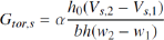
Figure 2: Shear field’s constructing square after deformation.

where  h0 is length of the un-deformed square diagonals (Figure 1), h and b are the cross-sectional depth and width, respectively, wi is the mean deformation of both diagonals of the square at both sides of the beam for the given shear load (Figure 2), Vs,i is the shear load as i being the load increment.
Although the square size was considered when assigning the shear correction factor (α), the impact of the size has not been experimentally investigated. This study aimed to study the impact of the size of the constructing square in the shear field test method. Since the recommended apparatus for measuring the shear distortion of the beam is limited to measure only one square at a time, the method is inefficient for this study. Therefore, a binocular stereo vision system was developed to capture the 3D displacement of a grid of target points. This approach is an accurate and noncontact method to extract the 3D coordination
of targeted object using two cameras. Six glue laminated beams were produced and tested according to the guideline given in BS EN 408 [1]. Analysis of Variance (ANOVA) was performed on the acquired data to evaluate the impact of size of the square in the determination of shear modulus of the beam.
Materials and Methods
Materials
Six laminated beams were produced. Three of the laminated beams were constructed as hybrid beams with three layers of timber and two layers of Laminated Bamboo Lumber. While the other three beams were constructed with five layers of timber. The beams were then tested in four-point bending test according to specifications given in BS EN 408 [1]. The beams were subjected to loading parallel to their glue lines. Each specimen was constructed with the dimensions of 142.5_190_3000mm, and then reduced to 142.5_178_3000mm to trim the excessive glues and flatten the surfaces. Phenol-Resorcinol Formaldehyde Resin (PRF) (Cascosinol Phenol Resorcinol Adhesive 1711 with Hardener 2520) produced by AKZO NOBEL, with minimum glue spread of 425g/m2 singlesided were applied (Figure 3).
Figure 3: Four-point bending test setup configuration.

Stereo vision system
The conventional method of measuring the displacement in the structural tests possess several limitations; they are limited to measure only one point and the physical interaction between measuring gauges and the specimen is often unavoidable. Because of these limitations, conventional methods could not be used in this research. Stereo Vision System is a triangulation-based approach, which allows us to determine the three-dimensional coordinates of any targeted point in the world and/or camera coordinate systems at any desired time [5,6]. Binocular vision system is similar to the method used by human and most of the animal's eyes for depth perception. The system works by taking two images of a scene of interest simultaneously from di_erent positions and angles. The employed system has described in details in Gharavi et al. [4].
Shear field test method
The shear field test was conducted following the specifications given in BS EN 408 [1]. Each specimen was supported vertically and transversely. The vertical supports were spanned 16 times the cross-sectional depth (h), while the lateral restraints were provided to prevent any transverse displacement. The loading was applied at the constant rate of 0.10mm/sec. The shear deformation of the beam was captured by binocular stereo vision system using two Canon EOS 70D cameras on one side and two Canon EOS 550D cameras on the other. All the cameras were equipped with 50 mm Canon EF f/1.8 II fix focal lenses. The cameras captured the images every 5kN load increment simultaneously till the fracture. The captured images were processed to extract the 3D coordinates of each target point in world coordinate system. Comparing every step with the initial coordinate of any target point reveals the displacement of the point in three dimensions. The target points were mapped on the side beams in a grid-like layout (Figure 4). Each target point can be considered as a corner of a square (Figure 4). Using each constructing square, the shear modulus of the beam can be determined following the equation 1. In this study the impact of the square size when the squares placed at the centre of the constant shear span was evaluated. The squares are symmetric to the neutral axis, this is due to the fact that the shear field test method is based on symmetric shear stress distribution over the cross-section of the beam [2].
Figure 4: Constructing squares in the case Four.

Results
Analysis of Variance (ANOVA) has been carried out on the impact of the size of the square in the determination of the shear modulus of the beam. The impact of the size of the constructing square on the variation of the shear modulus of the beam was analysed. As it can be seen from Figure 4, three squares with different dimensions were selected and based on the distortion of each square, corresponding shear modulus was determined. The shear modulus of each beam against the square sizes, i.e. Small, Medium and Large, are given in Table 1. The null hypothesis for the impact of square size was set to; "The size of the square will have no impact on the variation of the shear modulus of the tested beam". The ANOVA factor, F(2,15)=3:84, for the size impact rejects the null hypothesis. This implies that the size of the square will have an impact on the determination of the shear modulus. Based on the results of this experiments, measured shear modulus of the beam increased with the square size in five out of six tested samples. Authors think that the higher determined shear modulus in large squares may be due to heterogeneous characteristics of wood and non-uniform deformation near the edges of the timber. More research needs to be undertaken on the significance of the impact of the square size in the determination of the shear modulus for different cross sections and species.
Table 1: Measured shear modulus of the beam based on square size (Figure 4).

4P: 4-Point bending
Hi: Hybrid beam
Gi: Glulam control beams
i: {1,2,3}
Conclusion and Recommendations
The size ofthe constructing square in the shear field test method was examined using ANOVA analysis. The results of this study indicated that the size of the square has an impact on the mean shear modulus of the timber beam. It is recommended that the measuring square with the edge length of a half of the cross-sectional depth is an appropriate setup. Further research is required in order to draw a solid conclusion regarding the significance of this impact. Stereo vision systems are highly beneficial in the mechanical tests. These systems allow us to measure the 3D displacement, disparity, etc. of several target points simultaneously without any physical contact.
Acknowledgments
The authors would like to gratefully acknowledge the financial support provided by Lawrence Ho Research Fund and Peter KK Lee PhD Studentships. The help and assistance of Roshan Dhonju in the production and testing stages are greatly appreciated.
References
- BS EN 408, BSI (2010) Timber structures-structural timber and glued laminated timber-determination of some physical and mechanical properties. The British Standards Institution, London, UK.
- Brandner R, Freytag B, Schickhofer G (2008) Determination of shear modulus by means of standardized four-point bending tests. In: CIB W18, St. Andrews, Canada, USA, pp. 41-21-1.
- Brandner R, Gehri E, Bogensperger T, Schickhofer G (2007) Determination of modulus of shear and elasticity of glued laminated timber and related examinations. In: CIB-W18. Bled, Slovenia, Europe, pp. 40-12-2.
- Gharavi N, Zhang H, Xie Y, He T (2018) End effect on determining shear modulus of timber beams in torsion tests. Construction and Building Materials 164: 442-450.
- Valsaraj A, Barik A, Vishak P, Midhun K (2016) Stereo vision systemimplemented on FPGA. Procedia Technology 24: 1105-1112.
- Wohler C (2013) 3D computer vision: efficient methods and applications, (2nd edn), Springer, London, UK.
© 2018 Niaz Gharavi, et al. This is an open access article distributed under the terms of the Creative Commons Attribution License , which permits unrestricted use, distribution, and build upon your work non-commercially.
Editor In Chief


.jpg)


Signup for Newsletter

Quick Links
 Editorial Board Registrations
 Submit your Article
 Refer a Friend
 Advertise With Us
Our Recent Edition

.jpg)


Top Editors


.jpg)


.bmp)
.jpg)
.png)
.jpg)


.jpg)


.png)

.png)


.png)


Financial Support

Sponsors

Latest e-Books

Latest Video

 a Creative Commons Attribution 4.0 International License. Based on a work at www.crimsonpublishers.com.
Best viewed in
a Creative Commons Attribution 4.0 International License. Based on a work at www.crimsonpublishers.com.
Best viewed in