- Submissions

Full Text
Research & Development in Material Science
Design and Performance Enhancement of Vivaldi Antenna
Sunita Rani, Himanshu Monga* and Silki Baghla
Department of ECE, JCDM College of Engineering, India
*Corresponding author: Himanshu Monga, Department of ECE, Director of JCDM College of Engineering, Sirsa, Haryana 125055, India
Submission: December 04, 2017; Published: January 25, 2018

ISSN: 2576-8840Volume3 Issue2
Abstract
In this paper, a computer aided design of Vivaldi Antenna is developed which is used to study the effect of different parameters such as rate of opening of exponential slot and size of the radius of circular slot of the Vivaldi Antenna. The proposed design resulted in enhancement of gain and reduction in reflection losses. COMSOL Multi physics simulator is used to design the proposed Vivaldi antenna.
Keywords: Vivaldi Antenna; COMSOL Multiphysics; Copper Plate (FR4, 3.38 dielectric value)
Introduction
The Vivaldi antenna is a special kind of tapered slot antenna (TSA), having an exponentially tapered slot profile. It is first recognized by Gibson in 1979 [1-3]. It is useful for wide-band applications [4]. This research focused mainly on miniature antennas with a low losses and high gain. The aim of this research is to compute the far-field pattern and to compute the impedance matching of the structure [5,6] (Figure 1).
Figure 1: Vivaldi antenna structure.
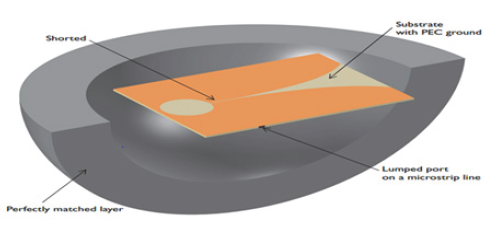
The proposed Vivaldi antennas consist of a micro strip feed line, micro strip line to slot line transition, and the radiating structure. Radiating structure is exponential tapered and the radiation takes place along the axis of the tapering [7-9]
This antenna comprises of three different types of slot lines which are:
a. The circular slot which is used to realize the impedance matching of the micro strip transmission line.
b. The rectangular slot which is used to couple the electromagnetic wave from the micro strip transmission line.
c. The exponential tapered slot which is used.
In this Vivaldi antenna model, the tapered slot is patterned with a prefect electric conductor (PEC) ground plane the top of the dielectric substrate. One end of the slot is open to the air and other end is finished with a circular slot. On the bottom of the substrate, the shorted 50Ohm micro strip feed line is modeled PEC surface. The entire molding domain is bounded by perfectly matched layer (PEC) which act like an chamber absorbing all radiated energy.
Related Work
Dhawan [1] Presented the design and detailed results of the Vivaldi Antenna with the selection of FR4(2.33) substrate material. This antenna is showing remarkable performance at a frequency of 7.5GHz and VSWR equal to-24.5dB with high directivity and narrow beam width. Ying [3] proposed one design that starts from a single balanced Vivaldi antenna unit, designs and analyses the electromagnetic characteristics of balanced Vivaldi antenna array. Then get a high-gain more than 35dB successfully by a parabolic antenna with the feed of 4 x 3 x 3 Vivaldi array. ANU [8] designed an antenna which used in the band from 2.1GHz to 9.2GHz with a fractional bandwidth of 125.66%. Corresponding to the design frequency of 2.8GHz a peak gain of 6.122dB and minimum S11 of -28.5dB is achieved [10-12].
Design Parameters of Proposed Antenna
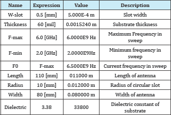
General parameters that are used during the design of Vivaldi are given in Table 1.
Table 1: Design parameters.
Design Procedure
The proposed VIVALDI antenna is designed using COMSOL simulate with following step:
a. Select the dimensions.
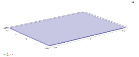
b. The Vivaldi antenna is realized on a thin dielectric substrate. The Vivaldi block with the dimensions given in Table 1 is drawn on substrate FR4. The length of the Vivaldi antenna is 110mm, thickness is 1.5mm and breadth is 80mm Figure 2.
Figure 2: Substrate.
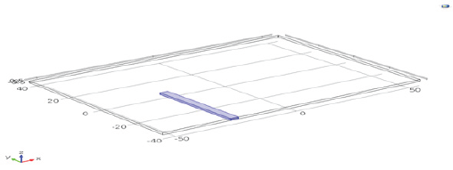
c. In the next step, feed line is selected. In this work the feed line with the line width=3.2, Depth=0+w_slot/2, Height =thickness breadth of 5mm and length 16mm is drawn. Shown in Figure 3.
Figure 3: Feed line.
d. Under a plane geometry node we define and create the geometry sequence for a work plane. The plane geometry node also contains some settings for the visualization of the work plane's geometry. Plane geometry for the proposed antenna with the radius of 10mm is show in Figure 4.
e. Apply electromagnetic wave in frequency domain and the antenna is made up of FR4 material with electrical permeability Figure 4-6.
Figure 4: Plane geometry.
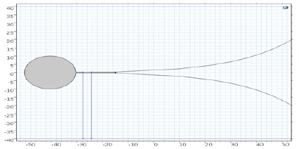
Figure 5: Electromagnetic waves, frequency domain.
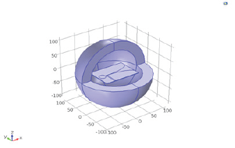
Figure 6: Mesh.
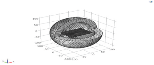
f. In this step, the antenna will be divided into small part. A The proposed antenna is analyzed with variation in radius mesh imported into COMSOL can be used to construct geometry.
Discussion & Results
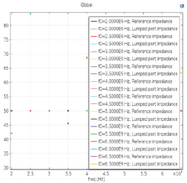
The proposed antenna is analyzed with variation in radius and it is found that at radius of 10mm. The designed antenna provides maximum electric field of 64 as show in Figure 7. When then electric field of Vivaldi antenna is 64 the designed antenna promotes the gain from 7.95dB in the desired frequency band (2 to 6.5GHz) as shown in Figure 8. The improved antenna gain can be used for applications like microwave imaging and radars. The result of our simulation can be seen in the form of SWR plot. According to our result SWR parameter is minimum 1.14 at 3.5GHz as shown in Figure 9 & Figure 10 Show the Far field radiation pattern for FR4, beginning frequency is 2GHz and 6.5GHz that is the finish frequency. In this far field, radiation pattern diagram highest output frequency at 4.5GHz. With the selection of feed purpose employed in this model, the S11 parameter is minimum at 3.5GHz as shown in Figure 11 & Figure 12 shows a good Impedance matching occur at 3.5GHz.
Figure 7: Electric field of Vivaldi antenna.
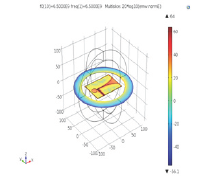
Figure 8: Gain of Vivaldi antenna.
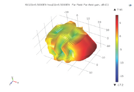
Figure 9: (SWR).
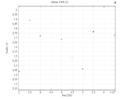
Figure 10: Far field Radiation Pattern.
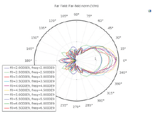
Figure 11: S-parameter.
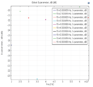
Figure 12: 1D Impedance matching.
Conclusion
The proposed Vivaldi antenna is simulated using the COMSOL. The proposed antenna is low- profile and uses low cost FR4 substrate. Here the geometry is not restricted and it takes a shape such that the objective of maximum gain and minimum S11 is achieved. The designed antenna can be design frequency from 2 to 6.5GHz. This antenna is showing good impedance matching performance at a frequency of 3.5GHz. The proposed antenna is giving high electric field of 64. Low reflection losses are -24 and gain of antenna is7.95db. The proposed antenna is low-profile and uses low-cost FR-4 substrate. To validate the simulation results, the antenna would be fabricated and tested in near future.
References
- Rajveer D, Gurkiran D (2016) Vivaldi antenna simulation on defining parameters, Parametric study and results. IJCTA 9(11): 5129-5138.
- Matthias J, Ammann MJ, Mcevoy P (2008) UWB vivaldi antenna based on a spline geometry with frequency band-notch. IEEE.
- Yang Y, Wang Y, Fathy AE (2008) Design of compact vivaldi antenna arrays for UWB see through wall applications. Electromagnetics Research 82: 401-418.
- Han X, Juan L, Changjuan C, Lin A (2012) UWB dual polarized vivaldi antenna with high gain. IEEE.
- Kerarti DZ, Marouf FZ, Meriah SM (2012) New tapered slot vivaldi antenna for UWB applications. 24th ICM.
- Debdeep S, Vaibhav S (2013) SRR-loaded antipodal vivaldi antenna for UWB applications with tunable notch function. Proceedings of The International Symposium On Electromagnetic Theory. IEEE.
- Chittajit S (2014) Some parametric studies on vivaldi antenna. International Jornal of U-And -E Service Science and Technology 7(4): 323-328.
- 8. Anu RGS, Santhosh K (2014) Tapered slotted vivaldi antenna design using fourier series approach for UWB applications. ICCSC.
- Pandey GK, Singh HS, Bharti PK, Pandey A, Meshram MK (2015) High gain vivaldi antenna for radar and microwave imaging applications. International Journal of Signal Processing Systems 3(1): 35-39.
- Kalyani PD, Narlawar MS (2015) Design of novel vivaldi antenna for cognitive radio application in ultra wide band 3(3).
- Osama MD, Tamer GA, Ashraf SM, Hadia MEH (2016) A novel UWB vivaldi antenna array for radar applications. International Journal Of Scientific & Engineering Research 7(5).
- Ying L, Ai-Xin C (2008) Design and application of vivaldi antenna array. IEEE.
© 2018 Sunita Rani, et al. This is an open access article distributed under the terms of the Creative Commons Attribution License , which permits unrestricted use, distribution, and build upon your work non-commercially.
 a Creative Commons Attribution 4.0 International License. Based on a work at www.crimsonpublishers.com.
Best viewed in


.jpg)


 Editorial Board Registrations
 Submit your Article
 Refer a Friend
 Advertise With Us
.jpg)


.jpg)


.bmp)
.jpg)
.png)
.jpg)


.jpg)


.png)

.png)


.png)


