
- About Us
- Information
-

The Author ensures that the research has been conducted responsibly and ethically with adherence to all relevant regulations. read more..
- For Authors
- For Reviewer
- Manuscript Guidelines
- Membership
- Publication Ethics
-
- Journals
- Reprints
- e-Books
- Videos
- Policies
- Contact Us
 COVID-19
- Submissions


Full Text
Peer Review Journal of Solar & Photoenergy Systems
A Study of the Transient Behavior of a Photovoltaic Park in a Lightning Strike
Ioannis A Naxakis, Konstantinos N Koutras, Efstathios N Apostolakis and Eleftheria C Pyrgioti*
High Voltage Laboratory, Department of Electrical & Computer Engineering, University of Patras, 26500 Patras, Greece
*Corresponding author: Eleftheria C Pyrgioti, High Voltage Laboratory, Department of Electrical & Computer Engineering, University of Patras, 26500 Patras, Greece
Submission: December 28, 2020;Published: November 01, 2021

Volume2 Issue1 November, 2021
Abstract
This paper deals with the study and installation of a lightning protection system in a photovoltaic park located in Epirus, Greece after a potential lightning strike event. The transient behavior of the grounding grid of the photovoltaic park under investigation was evaluated, for several situations of lightning strikes, through its simulation in the ATP - EMTP program taking into consideration the phenomenon of ionization of the soil.
Introduction
The production of electrical power from Renewable Energy Sources (RES) is an increasingly urgent need to meet the current energy requirements. Towards this direction, a number of photovoltaic systems have been installed, which due to their location, are often exposed to difficult weather conditions, such as lightning strikes. Therefore, the design and proper operation of a suitable Lightning Protection System (LPS) is necessary. In order to test its transient behavior after the exposal to a lightning strike, a simplified model of a photovoltaic system, consisting of a typical arrangement of solar modules, is taken into account. Simulations are carried out in ATP - EMTP program [1-3]. The pi-equivalent circuit was used to model the transient behavior of the grounding system, with lumped R-L-C elements based on Sunde’s equation [4-10]. Two cases are examined: Case A, where the lightning current is entering from a side point of the structure and Case B, where the lightning current is entering from a middle point, with and without taking into account the soil ionization phenomenon. The simulations are executed with soil ionization electric field E0 of 300kV/m and the value of the electrical resistivity of the soil ρ is picked as 100Ωm. The photovoltaic grid will be subjected to a lightning current 150kA (1.2/50μs).
The characteristics of the required LPS depend on those of the construction and the level of protection to be achieved, IEC 62305 [11]. The solar park under study is located in Epirus, Greece with the external dimensions being 39.66m length x 47.83m width, occupying an area of 1,897m2. It consists of 416 photovoltaic panels and generates total power of 140kWp, as displayed in Figure 1. Based on the data from the Greek Meteorological Service, the annual average density of lightning in Epirus is Td.=50 days/year km2, therefore following the procedure described in IEC 62305-3 standard, the protection level II is determined. Therefore, after the choice of the air termination system and the down conductors, the grounding grid is designed.
Figure 1:Solar park.

Ground Grid Model Description
Based on the aforementioned analysis, a grounding grid model is selected, and simulation is carried out. By means of the equations (1)-(4), the parameters of the pi-equivalent circuit (Figure 2) are calculated.
Figure 2: Pi equivalent circuit.

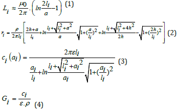
ρ=soil resistivity (ohms)
li=the total length of the ground electrode (m)
α=the diameter of the ground electrode (m)
h=the burial depth of the electrode (m)
μ0=the magnetic permeability of vacuum = 4π×10-7Hm-1
ε=dielectric constant of the soil (F/m)
αi = the equivalent diameter of the ground electrode when
ionization is included
In equation (5), for the calculation of the capacity ci, the equivalent diameter of the ground electrode ai (when the soil ionization is included) is calculated from the following equation in accordance with Mousa criterion [26]:

Imi=the current that is led to the point i (A)
E0=the intensity of the ionization field (V/m)
Calculation of the Ground Grid Elements
The ground resistivity ρ, the dielectric constant ε and the magnetic permeability μ0 were considered the same everywhere. The ground resistivity to be used is ρ=100Ωm. The dielectric constant will be ε=2.83x10⁻¹¹F/m. The earthing grid is of tape type and has an equivalent diameter α=40mm and the burial depth is h=1m. Initially, the simulations are performed without considering the ionization effect. Afterwards, new sets of measurements are performed which include the soil ionization. All the elements have been calculated for E0=300kV/m. The calculated parameters are presented in Table 1. The simulation of the ground grid is carried out at the ATP - EMTP program. The grid is constructed with combination of earthing mesh with earthing rods at each node of the grid. In the simulation, the connection of the metal support structure of the photovoltaic panels was also integrated, as depicted in Figure 2. The grid is subjected to a lightning current 150kA (1.2/50μs) at two different points, (Case A and Case B) neglecting the ionization effect. Subsequently, the same procedure was followed taking into account the soil ionization.
Table 1:Parameters of the simulation for ρ=100Ωm neglecting and regarding the ionization effect.

Simulation Result
Figure 3-6 show the resulted voltages at nodes 5, 11, 18 and 31, for applied current waveform of 150kA, 1.2/50μs ignoring and considering the soil ionization respectively. It is observed that in all cases the node of the current injection generates much higher voltage values in relation to the other nodes. Considering the phenomenon of ionization, the only parameter which is affected is the parallel capacity c and the conductivity G. The reason is that they depend on the cross-section area of the conductor thus the capacity c is increased, and the resistance G is decreased. These changes depend also on the values of the soil ionization field that is inversely proportional to the equivalent cross-section of the grounding conductor.
Figure 3:Current entering from the side of the structure (Case A) and Current entering from the center (Case B).

Figure 4:Case A-Voltages at nodes for 150kA (1.2/50μs) without soil ionization.

Figure 5: Case B-Voltages at nodes for 150kA (1.2/50μs) without soil ionization.

Figure 6: Case A-Voltages at nodes for 150kA (1.2/50μs) with soil ionization.

In Figure 7-9, the bar diagrams of the peak voltage values on nodes of interest are presented for both cases with resistivity ρ=100Ωm. In addition, Table 2 shows the peak voltage values appearing at nodes 5, 11, 18, 31, respectively, for lightning current 150kA, 1.2/50μs, resistivity ρ=100Ωm and E0=300kV/m. Figure 7-9, as well as Table 2, clarify the fact that the node of the current injection in Case A generates much higher voltage values with respect to the other nodes. It also shows that considering the ionization of the soil, the appearing voltage peaks are considerably lower than the case without taking it into account.
Figure 7:Case B-Voltages at nodes for 150kA (1.2/50μs) without soil ionization.

Figure 8:Case A- Bar diagrams at nodes for 150kA (1.2/50μs) with soil ionization.

Figure 9:Case B- Bar diagrams at nodes for 150kA (1.2/50μs) with soil ionization.

Table 2:Peak voltage values at 5, 11, 18, 31 nodes for lightning current 150kA, 1.2/50μs.

Conclusion
In this study, the efficiency of a proposed lightning protection system in a photovoltaic park located in Epirus, Greece is examined through simulation in ATP-EMTP. The grid is constructed with combination of earthing mesh with earthing rods at each node of the grid. From the presented simulation results, it is evident, as expected, that higher voltages appear at the node, which the injection current is applied. However, the occurring overvoltage at the striking node at the middle of the grid is lower than the corresponding one at the side. This could be explained based on the fact that, when the current is injected from the middle (Case B), there are more paths to disperse faster than in Case A. Also, the injection current in the more remote node in each case is very low, which means that voltage is decreasing drastically with the distance from the node. Finally, the influence of the soil ionization can be concluded from the peak voltage values appeared in the simulation. It is shown that the greater the ionization the smaller the displayed voltage values at the nodes.
References
- Dommel HW (1986) EMTP Theory Book, BPA, Oregon, USA.
- Lightning impulse performances of grounding grids for substations considering soil ionization.
- Pastromas SA, Naxakis IA, Xerra SI, Koutras KN, Pyrgioti EC (2020) Evaluation of wind turbine earthing system, proc of the 21st International symposium on high voltage engineering. Lecture Notes in Electrical Engineering 598: 316-328
- Sunde ED (1968) Earth conduction effects in transmission systems, Dover Publ. New York, USA.
- Sunde ED (1940) Surge characteristics of a buried bare wire. AIEE Trans 59: 987-991.
- Sunde ED (1949) Earth conduction effects in transmission system. Dover, New York, USA.
- (2009) Modeling of grounding electrodes under lightning currents. IEEE Transactions on Electromagnetic Compatibility 51(3): 559-571.
- Velazquez R, Mukhedkar D (1984) Analytical modelling of grounding electrodes transient behavior. Ieee Transactions on Power Apparatus And Systems 103(6): 1314-1322.
- (2011) Grounding grid transient analysis using the improved transmission line model based on the finite element method. European Transactions on Electrical Power Euro. Trans Electr Power.
- Lin Y, Guang Ning W, Xiao Bin C (2013) An optimized transmission line model of grounding electrodes under lightning currents. Science China Technological Sciences 56(2): 335-341.
- IEC 62305-3, Protection against lightning - part 3: Physical damage to structures and life hazard.
© 2021 Eleftheria C Pyrgioti. This is an open access article distributed under the terms of the Creative Commons Attribution License , which permits unrestricted use, distribution, and build upon your work non-commercially.
Editor In Chief


.jpg)


Signup for Newsletter

Quick Links
 Editorial Board Registrations
 Submit your Article
 Refer a Friend
 Advertise With Us
Our Recent Edition

.jpg)


Top Editors


.jpg)


.bmp)
.jpg)
.png)
.jpg)


.jpg)


.png)

.png)


.png)


Financial Support

Sponsors

Latest e-Books

Latest Video

 a Creative Commons Attribution 4.0 International License. Based on a work at www.crimsonpublishers.com.
Best viewed in
a Creative Commons Attribution 4.0 International License. Based on a work at www.crimsonpublishers.com.
Best viewed in