- Submissions

Full Text
Peer Review Journal of Solar & Photoenergy Systems
Smart Solar Photovoltaic Panel Cleaning System
Nasib Khadka1,2*, Aayush Bista1,2, Binamra Adhikari3, Diwakar Bista1,2 and Ashish Shrestha1,2
1Department of Electrical and Electronics Engineering, Dhulikhel, Nepal
2Center for Electric Power Engineering (CEPE), Dhulikhel, Nepal
3College of Engineering, Canada
*Corresponding author: Nasib Khadka, Department of Electrical and Electronics Engineering, Dhulikhel, Nepal
Submission: September 23, 2019;Published: October 21, 2019
Volume1 Issue3 October, 2019
Abstract
With the increasing demand for renewable energy, solar photovoltaic technology is being a topic of concern. However, due to the accumulation of dust and dirt over the panel surface, performance of photovoltaic system degrades to a noticeable amount. In order to address this issue: a fully automated, cost worthy and efficient system needs to be invented. This paper presents the design and fabrication process of a prototype along with its testing on a demonstration photovoltaic module; furthermore, depicting the implementation of the developed model on large-scale solar farms. The prototype of this system comprises of a cleaning robot and a cloud interface: the cleaning robot is mobile, and able to clean the entire solar array back and forth, with its separately driven cleaning rotatory brush; whereas, the cloud interface is a human-machine interface featuring the distant monitoring and control of the robot. Additionally, to notify the performance of distantly placed solar farm, a sensing unit consisting of sensors was added to this system, which updates the input and output parameters of the farm to the cloud interface. Furthermore, in this study, a month-long data of totally clean and dusty panel, were processed with regression analysis, and the regression model was developed to predict the suitable time for cleaning action. An Internet of Things based model is suggested for a large-scale solar farm having: a sensing unit, which senses the conditions of the farm; robotic unit: robots placed on each array of solar farm, which perform cleaning action if and only if, the command is sent from the operator or the sensing unit; and the cloud interface: interfacing each and every unit of the smart solar photovoltaic panel cleaning system.
Keywords: Renewable energy; Performance; Prototype; Solar farms; Robot; Cloud; Regression analysis; Internet of things
Introduction
Power generation from renewable sources has grown drastically in recent years, due to increasing energy demand as well as the environmental and economic concerns with fossil fuels [1,2]. Photovoltaic (PV) is one of the renewable energy sources with the greatest future projection as it possesses features such as simple installation, high reliability, low maintenance cost due to absence of moving parts and zero fuel cost [3]. Solar photovoltaic energy is harnessed from solar radiation; for a monocrystalline solar PV panel under standard test condition, it is seen that only 15-18% of solar radiation is utilized to produce electricity [4]. Achieving maximum efficiency has been a challenge and this efficiency changes due to several factors like: lower irradiance; higher air mass; higher temperature; regardless of this, solar radiation is failed to be harnessed due to accumulation of foreign particles like dust, bird excrement, snow, and many other [4]. Large scale PV systems are immensely affected by dust deposition on solar panels. Conventionally, the panels are cleaned with water and the process is labour intensive and is proven to be expensive in large scale PV system [5]. Accumulation of dust particle increases the temperature of solar panel up to 10% resulting decrease in net output power [6]. It not only increases module temperature, but also blocks the solar radiation that can reduce the system efficiency significantly. From an experimental study for two different setups: indoor and outdoor, it is evaluated that the efficiency decreased by around 30-40%, and in particular, moss deposition could reduce the output power by up to 86% [7]. An average of 1% with a peak of 4.7% in two month observation period was observed in the United States, 40% degradation in 6 month period in Saudi Arabia, 11% decrease in efficiency in the tropical climate of Thailand and from 33.5-65.8% reduction in efficiency from a study conducted in Egypt [8]. Making consideration to reviewed facts and figures interlinked with efficiency reduction, significant improvement in the output of the solar panels can be achieved by an effective method of cleaning.
There have been numbers of solar panel cleaning technologies, although very few or none of them includes condition-based solar panel cleaning. Dust covered solar photovoltaic panel might not need cleaning, or maybe cleaning action performed just due to visual inspection might not be effective in terms of economics. In fact, it is necessary to analyse that, whether the investment used to perform cleaning action covers the investment itself and regains the performance which was degraded due to dust deposition. Upon looking at the necessity of solar panel cleaning, it is very lucid that a complete system comprising of mechanical cleaner, a condition monitoring device and a better human-machine interfacing unit is required covering each and every aspect of power plant economics.
Different existing techniques for improving efficiency of the solar PV is discussed, which shows the practicality in the implementation of such inventions [4]. In this paper, a solar panel cleaning model is developed, and a 3D sketch is proposed for its implementation on large scale solar farms. Smart solar photovoltaic panel cleaning system consists of three major units: Robotic, Autonomous and cloud. A prototype of the proposed model is fabricated and experimented on 50Wp solar PV module of 660mm*600mm. Free body diagram is used to address the dynamics of the robotic unit. Autonomous unit consists of a couple of sensors in order to update the condition of solar panel covering output as well as environmental parameters. The regression model is programmed in the processor of autonomous unit and, is used to calibrate the automatic cleaning function of the model: to do so, the data collected from an experimental set up was processed. Human- Machine as well as Machine-Machine interfacing was achieved using third party cloud-based interface named UBIDOTS. With complete prototyping, a 3D sketch was done to represent the practicality of the Smart Solar Photovoltaic Cleaning System in solar farms. The novelty of this study lies within the implementation of Internet of Things and autonomous cleaning feature. However, some technoeconomic analysis is required before implementing the proposed cleaning system as depicted by aforementioned sketchs.
Model Development
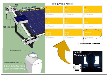
The developed model consists of two different units: Robotic Unit and Autonomous Unit. The two units communicate through an internet cloud-based platform known as UBIDOTS. Robotic Unit acts as a slave unit, as it follows command either from autonomous unit or from UBIDOTS interface directly on operator’s demand. The motors move robotic unit back and forth through the rails over the panel. Two limit switches are placed at right and left end to sense the end of the panel array. Also, robotic unit consists of a rotational brush which cleans the panel as the unit moves. The block diagram in Figure 1 shows all of the units comprising the proposed model.
Figure 1:Working mechanism of the proposed model: Block diagram.
Autonomous Unit, known as master unit, sends a command to robotic unit to perform cleaning action. This unit comprises of sensors to sense light intensity, dust density, temperature/humidity and output power in order to generate automatic cleaning signal and display the condition of solar panels/farm. The important three variables: illuminance, current and voltage (output power) are taken as the input parameter and real-time slope is calculated. This real-time slope is compared with slope of the reference line. If the real-time slope is less than the reference slope, the master unit sends a cleaning command to the slave unit. The autonomous unit keeps on sending command unless the performance of PV is recovered. Figure 2 represents the flow of automatic cleaning and gives thorough review of how autonomous unit work.
A cloud-based interface is used for human-machine as well as machine-machine interfacing; for the prototyping, third party webbased platform named UBIDOTS is used. Using UBIDOTS deviceagnostic API: Application Program Interface; any hardware can be connected to the UBIDOTS Cloud over HTTP Hypertext Transfer Protocol; MQTT: Message Queuing Telemetry Transport; TCP: Transmission Control Protocol; UDP: User Datagram Protocol or Parse a custom or industrial protocol
After successful connection of particle photon or any other hardware, data can be stored, manipulated, visualized in real-time, not only that it can generate an alert signal, if anything goes out of track [9]. In the devices section, real-time data is monitored showing each and every variable with real-time values associated with them; which can be depicted by Figure 3(a). In the dashboard section, acquired data is visualized in different forms like line, chart, double axis, scatter plot, histogram, and bars as shown in Figure 3b, 3c & 3d). In the same section, operator can send the cleaning signal through a switch as shown in Figure 3b. “Event” is a feature in UBIDOTS which notifies the user through email, text message, telegram or webhook under specified receiving network address, when certain parameters exceed the limit.
Figure 2:Working mechanism of the proposed model: Flowchart.
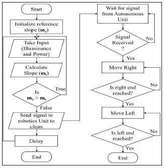
Figure 3:HMI interface Real Time Variables Updated. Operator’s Demand Button. Power vs Time. Illuminance vs Time.
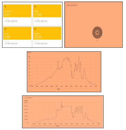
Figure 4:Free body diagram of robotic unit Where, μ=0.2(the coefficient of friction between mild steel and plastic tyre) [10] m= 5.37kg (mass of robot) N=Normal Reaction force g= 9.8 m/s2(acceleration due to gravity) 𝞡= Tilt angle 𝞃= Required Torque

Prototyping the Robotic Unit
The developed cleaning system model comprises of three major units viz. robotic unit, autonomous unit and cloud interface. In the following subsections, prototyping of the robotic unit is explained.
Idea generation
The question regarding the cleaning method used by the robot, its movement across the panel as well as adjacent panel is addressed by selecting the best choices among the listed ones in Table 1. To achieve effective cleaning, roller was selected as the best cleaning method among all other methods. To avoid the stress of cleaner weight and to achieve better mobility, movement across the panel and adjacent panel was expected to be achieved by attaching a separate rail at top and bottom ends.
Design evaluation and selection
Several designs were sketched, and among them the best design: robotic design was proposed and proceeded towards fabrication process. Different designs along with their defects are shown in Table 2. The reason for selecting a robotic design is primarily associated with its large-scale application. The requirement of separate power supply for robotic design can easily be addressed by the use of either lightweight battery or a separate solar module or both, over the top of it, which can supply the required power
Table 1:Idea generation with components and method selection.

Table 2:Different design and their defects.

Torque requirement of the selected design
The torque requirement of the motors used to drive the robot is evaluated using a free body diagram as shown in Figure 4. It is to be noticed that the weight of the robot is approximated by adding the weight of individual components to be fabricated. To calculate the torque required, it is assumed that sine component of total weight of robot is exerted at the upper end of rails, whereas the cosine component exerted at the lower end: under equilibrium condition [10].
The force required on lower part of robotic unit is given by Equation 1 and 2:
Fd = μ N1 (1)
Fd = μmg cosθ (2)
The torque required on the lower part of robotic unit is given by Equation 3:
τ d = Fd × radius of wheel (3)
Fd = 0.2 × 5.37 × 9.8 × cos30° = 9.11N
Td = 9.11 × 3.5 × 10−2 = 0.3189Nm
Thus, the force and torque required on the lower part of robotic arm are 9.11N and 0.3189Nm respectively.
Similarly, for the upper part of robotic arm we calculate force and torque using Equation 4, 5 and 6:
Fu = μ N 2 (4)
Fu = μmg sinθ (5)
τ u = Fu × radius of wheel (6)
Fu = 0.2 × 5.37 × 9.8 × sin30° = 5.2626N
τu =Fu × 3.5×10−2 =0.1482Nm
The force and torque required on the upper part of robotic arm are 5.2626N and 0.1482Nm respectively. It is to be noted that shaft of the motor at the upper end is perpendicular to the panel surface whereas, at the lower end, it is parallel. Hence, to match with the above torque requirement, appropriate motor with motor torque greater than 0.3189Nm and 0.1482Nm is to be selected.
Table 3:Evaluation of prototype developed.
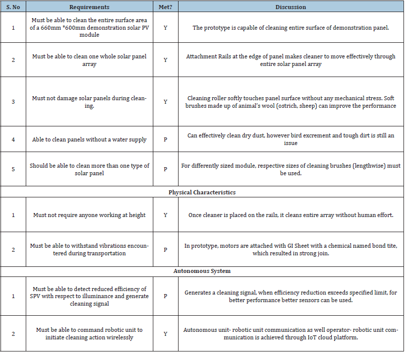
Key: Y/P/N = Yes/Partially/No
3D Design and fabrication of the robotic unit
The 3D design of robotic unit is shown in Figure 5, which majorly consists of stepper motor for translational motion, PMDC; Permanent Magnet Direct Current; motor for rotatory motion of cleaning brush, control circuitry box, power supply solar module. The fabricated prototype is shown in Figure 6 mounted on a demonstration solar module of 50Wp.
Control circuitry
The prototype of the robotic unit is operated by a microprocessor named particle photon; and has motor drivers for each motor controlled by digital pin of the microprocessor. Particle photon is capable of communicating solely with cloud through inbuilt wi-fi antenna connected to a wireless network connection.
Prototyping the Autonomous Unit
The autonomous unit consists of sensors and a microprocessor: Particle Photon. Data from sensors are taken by the I/O pins of the microprocessors. Particle photon communicates with cloud in same manner as in robotic unit. Autonomous unit mainly features real-time updates of the solar farm and automatic cleaning on performance degrade below a specified limit using a preprogrammed regression model.
Parameters and associated sensors
The autonomous unit prototype monitors input, output and influencing parameters which are directly or indirectly associated with the output power of the solar farm. In the prototype, light intensity is measured using illuminance sensor (TSL 2561), output power is measured using voltage and current sensor; additionally, influencing parameters like temperature and humidity are measured by DHT11 temperature and humidity sensor whereas, dust density is measured by a GP2Y1014AU0F dust sensor.
Automatic cleaning
The prototype of an autonomous unit is intended to generate a “time to clean” signal, when performance of the solar farm degrades below the specified limit. An experimental set up is done to develop a regression model by collecting data from two different scenarios: totally clean and completely covered dusty panel. The developed regression model is programmed in the microprocessor such that it detects the worst condition, when panel needs cleaning action.
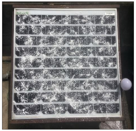
Experimental set-up: An outdoor experimental set up was done at Suryabinayak-09, Bhaktapur, Nepal (27˚39’10.3”N, 85˚27’37.2”E) using demonstration module (50Wp) inclined at 30˚ facing south. The experimentation was done for two different scenarios: totally clean module and dusty solar module as shown in Figure 7. Mainly two parameters are taken into consideration: illuminance and the output power, which are measured by their respective sensors. The experimental setup was left under natural sunlight condition for both with and without dust scenarios covering most of the illuminance’s values from, cloudy to clear and day to night. The value of illuminance and output power is taken at a sampling rate of 5 seconds and saved at cloud interface. It is to be noted that the sensor used to measure input sunlight has limitation up to 40,000lux [11], whereas at clear sky condition it is found to be 107527lux [12]; so , the output power below 40,000 lux is considered in this experimentation.
Figure 5:Robotic unit: 3D model.
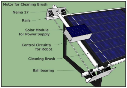
Figure 6:Robotic unit: Fabricated prototype.
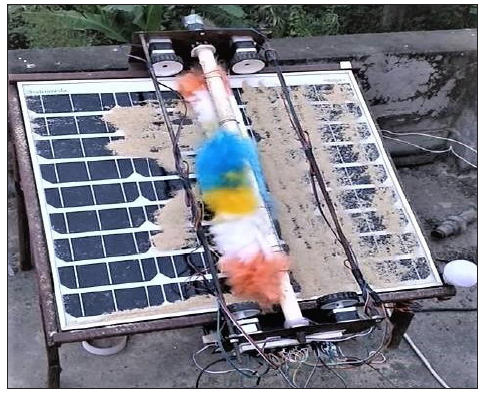
Figure 7:Experimental setup.
Regression model: The raw data collected from the experimental set up was retrieved from the cloud interface and processed through data pre-processing techniques: transformation to reduce noise and variability, feature selection to remove redundant and irrelevant data. Afterwards, regression analysis of the processed data is done in order to find the relationship between input variable: illuminance and output variable power. On finding the linear relation between input light and output power, a line of best fit using least square method is plotted from the regression analysis so done as shown in Figure 8(a & b). The equation of line of best fit were y = -2.6282350 + 0.0009607x for a clean panel; and y = 1.2287555 + 0.0002992x for a panel with dust.
Figure 8:Output characteristics of Dusty Panel. Clean Panel.

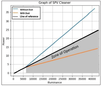
A regression model is developed by combining both linear regressions in a single plot. Slope of two lines of best fit is averaged as in Equation 7, which defines the zone of operation as shown in Figure 9. This zone of operation defines the condition, whether the solar plant requires cleaning action or not. If the coordinate defined by solar input and output power at any instant of power generation falls under zone of operation, the autonomous unit either notifies the operator or commands the robotic unit that cleaning action is required. The coordinate at particular instant along with the origin is joined to represent a line, whose slope termed as real-time slope as shown in Equation 8 is compared with the reference line assuring that the coordinate falls under the zone of operation.
Figure 9:Zone of operation for automatic cleaning.
Implementation at Large Scale Solar Farm
The accumulation of dust might not affect significantly in case of small-scale production, however, if the production is in the range of megawatts, even 1% reduction in efficiency might significantly affect the IRR (Internal Rate of Return) of the project. Smart Solar Photovoltaic Panel Cleaning System is mainly focused on its application in large scale solar farm having uniform solar arrays throughout the plant.
On making site visit
Smart Solar Photovoltaic Panel Cleaning System can be used in two different ways depending upon the site location. If the site is near, it is suggested to implant a single autonomous unit at the site which monitors the condition of the plant: output power, input light energy, temperature, humidity, dust density. Whenever the autonomous unit detects performance of plant under zone of operation, it alerts the operator and suggests performing cleaning action using a single robotic unit. Same robot is detached from the array and transferred to next array after cleaning the complete array back and forth and this process is continued until whole solar farm is cleaned. The advantage of this type of cleaning procedure is that it requires a single robot.
Without site visit
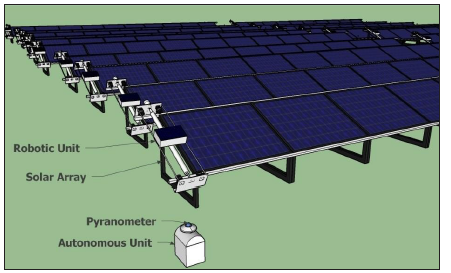
If the site is very far to reach involving high transportation cost, or if the site is subjected to frequent sand storm, it is suggested to implement a different model. Solar panel cleaning in aforementioned site can be cleaned without making a site visit, and to do so: multiple numbers of robotic unit need to be placed on each of the arrays. An autonomous unit is placed to sense the real-time condition of the site as mentioned earlier before. The autonomous unit is considered as master unit and commands robotic units to clean their respective array; else looking upon the condition of the plant, operators themselves can command robotic units remotely. If transportation to the site becomes expensive in comparison to multiple robotic unit installations, site can be modelled as shown in Figure 10.
Figure 10:3D modelling of the cleaning system with robots at each of the arrays.
System Evaluation against Requirements Set
The evaluation of the prototype developed for the Smart Solar Photovoltaic Panel Cleaning System is evaluated under requirements set at the initial state of prototype development and can be illustrated as shown in Table 3.
Conclusion
In this paper, an Internet of Things based model naming Smart Solar Photovoltaic Cleaning System is presented, mainly focusing its implementation on a large-scale solar plant with standard panel configuration. The main goal of this work is to develop a cleaning system which requires least human effort. This model consists of two units: Robotic and Autonomous along with cloud-based Man-machine interface. These two units and human operator can communicate with each other via a cloud-based interface known as UBIDOTS.
The robotic unit was prototyped by fabricating a stepper motor driven robot capable of moving back and forth along the array through the added square section rails. To make the system even smarter and effective, autonomous unit was added. Autonomous unit measures the performance parameters of the solar plant and helps the operator making decisions, whether to perform cleaning action or not. For a distant solar farm site, automatic cleaning makes job easier, where cleaning action is achieved without making travel to the site. To achieve this function, an experimentally based calibration model needs to be programmed in the processing unit of the autonomous unit, practising the basics of Machine Learning. The autonomous unit generates an autonomous signal at the time of need and commands robotic units placed in each solar array. However, to implement automatic cleaning, each array requires a separate robotic unit. The innovation of this work is the automatic cleaning, which can be proven most effective for a large solar farm located in semi-arid areas, where frequent cleaning is required due to sand deposition. Additionally, before implementing the proposed model of Smart Solar Photovoltaic Panel Cleaning System, a cost worth based economic analysis must be done to make sure that the investment a plant owner willing to make on cleaning system will generate revenue in accordance to plant size, location: majorly the environmental conditions that the plant is subjected to.
Acknowledgement
This study was conducted at the Center of Electric Power Engineering (CEPE), Kathmandu University, Nepal, and funded by the Energize Nepal Project Office, Kathmandu University (PID: ENEP-CEPE-18-01).
References
- Komoto K, Cunow E, Breyer C, Faiman D, Megherbi K, et al. (2012) IEA PVPS Task8: Study on very large scale photovoltaic (VLS-PV) 38th IEEE Photovoltaic Specialists Conference pp: 001778-001782.
- Mondal AK, Bansal K (2015) A brief history and future aspects in automatic cleaning systems for solar photovoltaic panels. Advanced Robotics 29(8): 515-524.
- Chine W, Mellit A, Pavan AM, Kalogirou SA (2014) Fault detection method for grid-connected photovoltaic plants. Renewable Energy 66: 99-110.
- Khadka N, Adhikari B, Bista A, Shrestha A (2018) Solar panel cleaner technology: A 5th International Conference on Developments in Renewable Energy Technology, Kathmandu, Nepal.
- Mazumder MK, Sharma R, Biris AS, Horenstein MN, Zhang J (2011) Chapter 5-electrostatic removal of particles and its applications to self-cleaning solar panels and solar concentrators. Developments in Surface Contamination and Cleaning. pp: 149-199.
- Dorobantu L, Popescu M, Popescu C (2011) Yield loss of photovoltaic panels caused by 7th International Symposium on Advanced Topics in Electrical Engineering (ATEE), pp: 1- 4.
- Sulaiman SA, Singh AK, Mokhtar MMM, Rabee BMA (2014) Influence of dirt accumulation on performance of PV panels. Energy Procedia 50: 50-56.
- Hassan A, Rahoma UA, Elminir HK, Fathy A (2005) Effect of airborne dust concentration on the performance of PV modules. J Astron Soc Egypt 13(1): 24-38.
- IoT and cloud tools. Ubidots, USA.
- Coefficient of friction, rolling resistance and aerodynamics.
- Adafriut TSL2561 Luminosity Sensor.
- (2004) Illuminance-recommended light level. Toolbox E.
© 2018 Nasib Khadka. This is an open access article distributed under the terms of the Creative Commons Attribution License , which permits unrestricted use, distribution, and build upon your work non-commercially.
 a Creative Commons Attribution 4.0 International License. Based on a work at www.crimsonpublishers.com.
Best viewed in


.jpg)


 Editorial Board Registrations
 Submit your Article
 Refer a Friend
 Advertise With Us
.jpg)


.jpg)


.bmp)
.jpg)
.png)
.jpg)


.jpg)


.png)

.png)


.png)


