- Submissions

Full Text
Novel Research in Sciences
Porous Titanium Composite Plates for Electrolyzers - A Contribution to Faster Acceptance of Lower-Cost Electrolyzers
Thorsten Hickmann*
Eisenhuth GmbH & Co. KG, Germany
*Corresponding author: Thorsten Hickmann, Eisenhuth GmbH & Co. KG, Friedrich-Ebert-Straße 203, D-37520 Osterode am Harz, Germany
Submission: September 20, 2021;Published: October 08, 2021
.jpg)
Volume9 Issue3October, 2021
Mini Review
An almost abrupt change in attitude towards applications in the field of renewable energies
has emerged in recent months, both among decision-makers in politics and in companies [1].
In particular, the topic of hydrogen production by electrolysis plays an eminently important
role. In water electrolysis, water is split into its constituent ¬parts hydrogen and oxygen using
electrical energy. The resulting hydrogen is of interest to future energy systems for a number
of reasons, including the fact that hydrogen can serve as a storage medium for electrical
energy from renewable energy conversion systems such as photovoltaic or wind turbines
[2]. Polymer electrolyte membrane water electrolysis is considered particularly suitable for
this type of application. In polymer electrolyte membrane water electrolysis, the water to be
split is fed via so-called porous transport layers to the catalyst layer where the water splitting
takes place. These porous transport layers must ensure the outward transport of the water,
the outward transport of the produced gas, and the electrical contacting of the electrode [2].
While a few years ago the topic of liquid metal injection molding made a furor and became
established in some industrial sectors, the technologies presented here to produce composite
materials from metallic powders has been able to establish itself in the energy storage media,
i.e., especially in hydrogen production [3]. The key idea here is that conventional polymers
are combined with the powders. For example, titanium powder is shown in (Figure 1).
Metal composite sheets can be produced in a continuous process. The tool geometry plays
an important role in the extrusion process. The plastic melt provided by the extruder flows
through the flow channels inside the die and is reshaped towards the outlet cross-section.
It turns out that the flow processes in the extrusion die have a significant influence on the
quality of the end product. The dimensioning of the flow channel geometry depends on a
variety of requirements and shows a significant dependence on the specific rheological
properties of the plastic melt, especially when highly filled materials are involved [3].
The next step is the extrusion process with the die shown in (Figure 2). Here it is
important that the temperature control is very homogeneous. This should also be investigated
in advance. After the extrusion process, the melt has to be cooled down and, if necessary,
smoothed [4]. Continuous production of the plates is possible. The decisive factor is that the
parameters can be set in such a way that porous plates can also be produced, which can then
be used as Porous Transport Layers (PTL). It is important that an exact quantification of the
permeation takes place accordingly, therefore the measuring method is explained in more
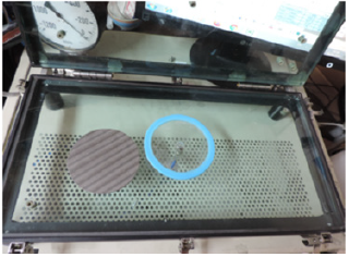
detail, see also (Figure 2). The plates are inserted between 2 glass plates in a U-shaped seal
made of silicone and are subjected to vacuum from one side. The other side is connected to the
atmosphere. After reaching the specified negative pressure, the vacuum side is hermetically
sealed. The subsequent change in pressure within a fixed time window is a measure of
the permeation through the test specimen. The measurements were carried out with the permeation measuring and testing system developed by Eisenhuth.
The procedure is as follows: First, the referencing is carried out.
For referencing, a geometrically identical dense acrylic disc with
the same seal is used.
Figure 1:Mixture of polymers and titanium powder to titanium composite material.
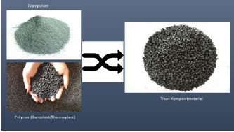
Figure 2:U-shaped ring seal together with a test specimen on the measuring device.
Calibration: The calibration refers to the determination of the
dead space, i.e., the volume that results from the measuring hoses
between the sample, pump, valves up to the transmitter (pressure
¬measurement). The dead space was determined with 15ml.
Calculation: The following algorithm is used to calculate the
permeation:
Qv=3600*Delta p*Vtot/(Delta t*pu)
Here the values are:
Qv ml/h Permeation
delta p mbar Pressure change during the measuring
time
Vtot ml dead volume=measuring volume
pu mbar Ambient pressure
The test procedure in the test device developed by Eisenhuth
is as follows:
Phase 1: After inserting the test specimen into the seal and
after closing the test device, the vacuum pump is switched on and
switched off at approx. 800mbar negative pressure.
Phase 2: Then the system check takes place for approx. 4s
together with the test object, without throttle distance to the
outside.
Phase 3: Throttle path to the outside with test specimen.
Phase 4: Hermetic sealing of the measuring device.
Phase 5: Relaxation time for seal, test item is active.
Phase 6: Start of measurement=>start pressure, time window
starts.
Phase 7: Measuring time.
Phase 8: End of measurement.
The permeation quantity is calculated per time period. The test
specimen in the seal lies tightly on the glass plate. A laterally airpermeable
felt plate is located on the test specimen. An upper plate,
acting as a plane weight force, presses the felt plate onto the test
specimen. Thus 2 test areas are created: On the one hand, there is a
measuring field under the test specimen as vacuum and measuring
space, on the other hand, there is the space with ambient pressure
above the test specimen. Permeation through the test specimen
therefore takes place from top to bottom. The pressure ¬measured
over time in the vacuum chamber is reflected in the permeation
flow. The ¬dead space is of decisive importance here. The smaller
the dead space, the steeper the pressure curve and vice versa. From
the (Figure 3) it can be seen that the pressure is maintained at about
500mbar after the start of the test procedure (after 10 seconds).
Constant pressure means: plate is tight. In the following, it is shown
for a permeable plate which can be used as a Porous Transport
Layer. (Figure 4) shows that the pressure is not maintained after
starting the test procedure (after 10 seconds). Falling pressure
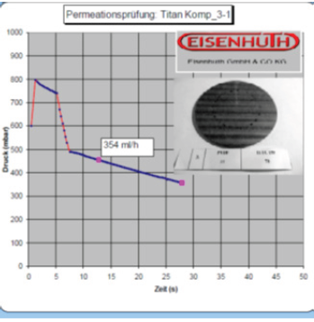
means: plate is slightly permeable. (Figure 5) shows that the
pressure is not maintained after starting the test procedure (after
10 seconds). A strongly decreasing pressure can be observed. This
means that the plate is highly permeable and suitable as a porous
transport layer.
Figure 3:Titanium composite plate: The curve from approx. 10 seconds is horizontal.
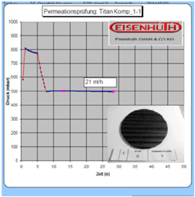
Figure 4:Titanium composite plate: The curve from approx. 10 seconds onwards drops very slightly.
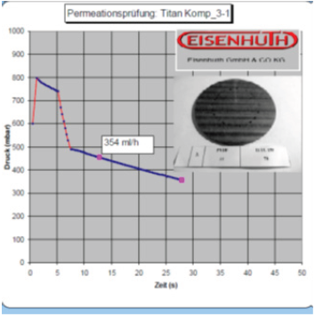
Figure 5:Titanium composite plate: The curve from approx. 10 seconds onwards drops very slightly.
Acknowledgement and Funding
The works were created in the project “Autark Elyss BB”. The project is funded by the state of Brandenburg via the ILB under the funding code 80257166, for which Eisenhuth, located in Wildau, would like to express its sincere thanks. The project is co-financed by the European Regional Development Fund (ERDF).
References
- (2019) Communication from the Commission to the European Parliament, The European Council, The Council, The European Economic and Social Committee and The Committee of the Regions: The European Green Deal, Brussels.
- Höh M (2017) Porous transport layers for polymer electrolyte membrane water electrolysis. PhD Thesis, 388: 1-203.
- Hickmann T (2008) Plastic applications in PEM fuel cells. VDI Reports, pp. 81-83.
- Bonnet M (2013) Plastics technology. Hamburg: Springer Verlag, USA.
© 2021 Thorsten Hickmann. This is an open access article distributed under the terms of the Creative Commons Attribution License , which permits unrestricted use, distribution, and build upon your work non-commercially.
 a Creative Commons Attribution 4.0 International License. Based on a work at www.crimsonpublishers.com.
Best viewed in


.jpg)


 Editorial Board Registrations
 Submit your Article
 Refer a Friend
 Advertise With Us
.jpg)


.jpg)


.bmp)
.jpg)
.png)
.jpg)


.jpg)


.png)

.png)


.png)


