- Submissions

Full Text
Integrative Journal of Conference Proceedings
Design and Optimization of Structural Energy Absorbers to Improve the Vehicle Crash Behavior in the Longitudinal and Transverse Directions
Moeid Hamidi and Fariborz Forouhandeh*
Department of Engineering, Shahrood Branch, Islamic Azad University, Shahrood, Iran
*Corresponding author:Fariborz Forouhandeh, Department of Engineering, Shahrood Branch, Islamic Azad University, Shahrood, Iran
Submission: February 16, 2023;Published: April 03, 2023

Volume3 Issue3April, 2023
Abstract
An accident or crash is an occurrence, where a force is imposed on the occupant during a very short period of time. Therefore, in designing the car structure and body, the accident time is increased to the most possible value. The purpose of the structure and body design is to absorb the maximal energy in the accident. This research tried to design and optimize a crash box to absorb the maximum energy and minimum force in the longitudinal and transverse impacts of the crash. A numerical simulation and an experimental test have been done to ensure its response accuracy. After taking a proper finite element model, considering the factors and variables levels in the structure, optimization has been also done to determine the best plan for maximum energy and minimum force absorption objectives. In this research, three factors of sheet thickness, number of inner squares, and profile material were considered with three levels for each factor. The thickness of 2, 4 and 6mm, the number of squares 1, 4 and 9 and the materials of aluminum, steel and copper have been investigated. They showed that the optimal thickness and the number of squares are 6mm and 9 respectively.
Keywords: Structural energy absorber; Vehicle crash behavior; Bending test; Longitudinal and transverse impact
Introduction
Safety of cars is one of the key factors in preventing losses in accidents. Thousands of people die every year on road accidents annually. Road accidents are one of the main causes of death in the world. So, the occupant’s safety is one of the areas that have attracted the automotive industry in recent years for designing the vehicles and cars. The need to protect the occupants in the accident happened from the front, back and the other sides have made modern cars equipped with a variety of systems. The purpose of the proper design of a car is to minimize the acceleration imposed to the occupant’s during the crash, which requires that the largest share of the energy resulting from the crash in the structure becomes absorbed by the momentary momentum and in the form of deformation energy, which makes the least distortion and damage to occupant’s chamber. In this regard, the designers have focused on two factors of body geometry and mechanical properties of new materials.
An accident or crash is a very brief occurrence, and during this short period of time, a crash force is imposed to the occupant. In designing the structure and body of the car, it is attempted to increase the crash time as much as possible. In this research, it was tried to design an optimal structure for maximal energy absorption in two conditions of longitudinal and transverse collisions. In this way, improvements have been made to the structure to reduce the acceleration of the occupants. Given the fact that the longitudinal and transverse rails in the structure of the vehicle are crucial for absorbing the energy of the accident and reducing the acceleration of the occupants, this problem has been investigated and its various forms in energy absorption and reduction of losses in the accident have been also analyzed. It should be noted that that in this study, the collision will be investigated in both the longitudinal and transverse modes, and the optimal mode will be extracted.
Numerous studies have been conducted on energy absorbers. Keskin et al. [1] investigated diaphragm-based methods to improve the performance of crash absorbers in rail vehicles. They investigated the effect of parameters such as the dimensions of the pipe and the optimal diaphragm, the location of the optimal diaphragm and the cone angle. They showed that by optimizing the energy absorption system, the Maximum specific energy absorption (SEA) can be increased up to 69.4%. Mortazavi Moghaddam et al. [2] designed a car crash box using a corrugated conical tube. In their research, they used Abaqus finite element software and did a pseudo-dynamic simulation of the problem. They showed that the use of corrugated thin-walled tubes under axial and diagonal loadings deforms regularly and almost stably. Bhardawaj et al. [3] analyzed the crash box in frontal crashes using ANSYS software. They investigated steel and aluminum for the crash box and also used square and rectangular geometries. They showed that the use of square geometry compared to rectangular geometry increases the amount of specific energy absorption by 16% and the maximum bearable force by 15%. Also, although the use of aluminum reduces the weight by 63%, the amount of specific energy absorption is reduced by 24% and the maximum tolerable longitudinal force is reduced by 64%. Xu et al. [4] addressed the multi-objective optimization of composite energy absorbers for rail vehicles. Their absorber was made in the shape of a bee nest. They used the particle swarm method for optimization. They showed that the energy absorber made of composite has better performance compared to other samples. Demirci and Yildiz [5] investigated crash boxes with different materials of magnesium, aluminum and high strength steel as well as different cross-sectional geometries. The ability to absorb energy of steel absorbers is better than aluminum and magnesium absorbers. On the other hand, energy absorption capacity per unit mass of energy absorbers made of lightweight materials is higher than steel energy absorbers. This advantage of lightweight alloys encourages car manufacturers to use them in the design of car structural components. Pyrs and Krzywoblocki [6] tried to optimize the crash box of thin-wall tubes using the macro element and evolutionary algorithm. In this research, a suitable route has been introduced to obtain the desired configuration of thin wall tubes for the construction of a crash box. The purpose of this work was to determine the optimal cross-sectional dimension of a tube to achieve maximum absorbed energy. Two optimization algorithms and visual studio software have been used there and the impact test has been evaluated for optimization process. In this process, squared and hexagonal tubes exposed to axial load have been investigated and the responses obtained from both optimization methods were compared. The obtained results are also in good agreement with those of the FEM and experimental tests.
Li et al. [7] filled three types of traditional crash boxes with honeycomb structures. Quasi-honeycomb core, the quasisquare honeycomb core, and the hexagonal honeycomb core. The evaluations have shown that the energy absorption has been enhanced in those three new structures. Still, the collision force was reduced in the quasi-honeycomb structure by 8.9% and the two others faced an increment of 5.6% and 9.6% in peak impact force for the hexagonal honeycomb core crash box and the quasi-square honeycomb core crash box respectively. Moreover, the result of filling all three types of crash boxes with Expanded Polypropylene (EPP) foam, was the increase of peak collision force in the EPP hexagonal honeycomb core crash box and the EPP quasi-square honeycomb core crash box.
“Investigating the performance of the crash box with a thin wall in energy absorption: Recent advances and future progress” is the title of research carried out by Baroutaji [8]. In the research, it has been mentioned that during the past decades considerable research and efforts have been made to reduce losses and deaths in accidents, in which the vehicle is put under impact load. Thin wall tubular components have been widely used in energy absorbing structures to reduce the destructive effects of impact loading during an accident, thus increase the performance of the structure. Comprehensive knowledge of material specifications and structural behavior of different parts in various loading conditions is essential for designing an effective energy absorption system. In addition, in this research, extensive studies have been conducted on the recent advances in the performance of impact in thin-walled tubes (focusing on subjects of the past decade, including the design of failure optimization and energy absorption responses from unconventional thin-walled structures, including multi-cell tubes, classified thick tubes and filled tubes). Thin wall tubes are widely used as energy absorption components. Yang [9] introduced a paper entitled Energy absorption of thin-walled tubes with prepacking origami patterns in which numerical simulations and empirical tests have been also performed. The effects of origami patterns have been investigated on energy absorption capacity and deformation of concrete structures. The results showed that the initial origami force was significantly reduced, while the energy absorption capacity could be improved or maintained. Zhang [10] conducted a study entitled «Crash box operation with conical tubes and nonlinear thickness distribution”. In this research, the performance of the accident box with conical tubes and different thickness distribution has been investigated.
The samples are made with the tube shrinkage process and axial collision tests are performed to determine the energy absorption properties. In order to improve the performance of the crash box, the benefits of tube shrinkage are reduced. During the tube shrinking process, by simultaneous increase of the thickness and hardness of the material, the energy absorption increases up to 1.2 times. In addition, although after the shrinking, the maximum force of the tubes increases, the uniformity of the load improves with respect to the increase in the failure force. Research was conducted by Mohsenizadeh et al. [11] entitled “Experimental Investigation on Energy Absorption of Auxetic Foam-filled Thinwalled Square Tubes under Quasi-static Loading”. The Auxetic materials are placed in the new material classification, which have significant benefits in terms of industrial and mechanical properties. Contrary to conventional materials, these materials have a negative Poisson coefficient under non-axial loading. In this study, it was tried to check the experimental conditions of the collision response and energy absorbed by the hollow square tubes and also the tubes filled by this type of foam, takes into account the type of deformation and the force-displacement curve. For this purpose, common standards for pipe tests have been also used. The results show that the tubes filled by this type of foam have a higher absorption capacity compared to the empty tubes. In addition, it has been shown that in this type of tubes, by increasing the severity of impact, the loading capacity is also increased. In presenting the results obtained in this study, the use of these types of pipes filled with acoustic foam has been confirmed for the cases which require the impact safety.
Sun et al. [12] explored a powerful discrete optimization algorithm based on the Taguchi method for designing the structure of the crash box. Structural optimization is one of the most important tools for improving the welded structures in the accident box. To do this, a powerful and innovative optimization algorithm has been proposed based on Taguchi’s approach. The study attempts to find out how to maximize the absorption of impact in welded structures, including suspect cases. For this purpose, a powerful and longterm optimization algorithm was initially presented based on the successful Taguchi approach for design purposes in a discrete space. In optimization process, maximum force was set as a target, while specific energy absorption (SEA) was considered as a limitation. The optimal results showed that not only the maximum force and specific energy absorption were improved, but also the strength of these two indicators was also increased significantly. The proposed algorithm could be used in other complex engineering problems to solve them.
Experimental test setup
In order to perform three-point bending tests and compression test, a device available in the Mechanical Laboratory of the University of Science and Technology has been used. The device (SANTAM and the STM-150 series) has a load cell to measure the applied pressure with a power rating up to 150kN.
Preparation of test samples
In order to conduct an experimental test, an aluminum profile was prepared, with a thickness of 2mm, cross section of 2cm* 2cm and length of 20cm. Note that two sets of separated sample profiles have been prepared for conducting two compression tests and two three-points bending tests.
Uniaxial tensile test
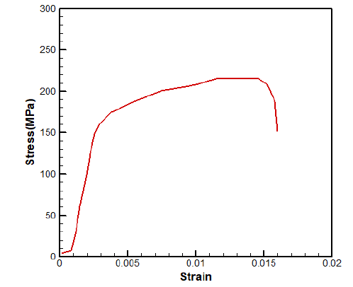
In order to obtain the mechanical properties of the prepared parts, it is required to take the uniaxial tensile test. The ASTM B557M [13] standard has been used to carry out this test. The stress-strain curve obtained by this test is shown in Figure 1.
Figure 1:The stress-strain curve obtained by the uniaxial tensile test.
Experimental test
Two compression tests (in order to simulate the longitudinal collision) and a three-point bending test (in order to simulate the transverse collision) have been performed to validate the finite element model.
Three points bending test
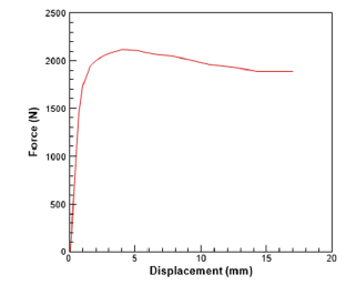
As stated, the three points bending test was used to evaluate the energy absorption in a transverse collision. Figure 2 shows the profile installed on the machine for this test (Figure 3).
Figure 2:Installation of the part in order to perform the three-points bending test.
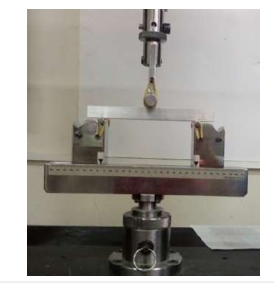
Figure 3:Force-displacement curve of the three points bending test.
The compression tests
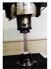
A compression test is also used to simulate a longitudinal impact. As shown in Figure 4, the part is mounted on the machine and is ready to take the compression test.
Figure 4:The part mounting and mounting clogs to conduct the compression test.
Simulation of Finite Element
In order to evaluate the amount of energy absorbed in different profiles, a finite element model is required to be validated by experimental test. ABAQUS analyst software has been used in this way. The Shell model has been also used via the properties of the materials obtained by the tensile test. The S4R mesh and R3D4 mesh have been used for modeling of profiles and the rigid parts, respectively. The properties of the used materials are listed in Table 1 (Figure 5,6).
Table 1:Properties of the aluminum materials obtained by the tensile test.

Figure 5:The force-displacement graph obtained by the compression test.
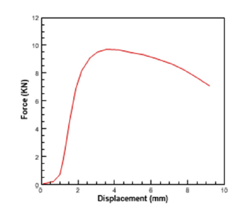
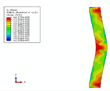
Figure 6:Tension contours of the compression model.
Simulation of compression test
In order to simulate the pressure test, an analytical rigid plate is used to compress the profile. Also, the lower part of the profile is fully bonded and the rigid plate moves downwards. Note that the rest degree of freedom of the rigid plate are also bonded. The connection of this rigid plate to the profile is through the Tie bond, in which case, the movement of the rigid plate and the upper edges of the profile are coupled together. After simulating and moving the rigid plate, the part is deformed similar to what shown in Figure 7. Tension contours are also observed in this Figure 7.
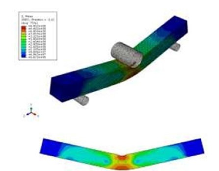
Figure 7:The tension contour of the three-point bending model.
Simulation of three-point bending test
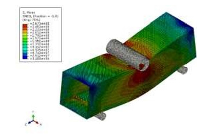
In order to simulate a three-point bending test, three fixtures that was used in the experimental test should be modeled. Two cylinders have been fixed below the part and one cylinder I set at the top of the profile for bending operations. The connection between the rigid parts and the profile surfaces is made by surface to the surface contact. After taking the simulation, the deformed profile along with the tension contour is according to Figure 8.
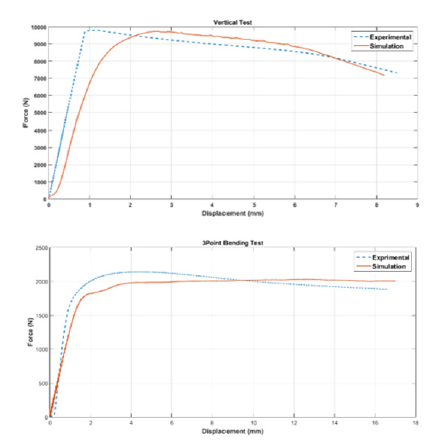
Figure 8:The force-displacement diagram of the compression test, b. The force-displacement diagram of the threepoints bending test.
Validation of the finite element model
In order to ensure the accuracy of the responses obtained from the finite element model, the force-displacement diagram obtained from the simulation was compared to the graph of the experimental tests. Figure 9 show the comparison of the obtained results obtained by the experimental and numerical simulation. As could be seen, the mean difference of two graphs is 15%, which indicates the accuracy of the finite element model. This difference is also due to the inaccuracy of the model construction and the normal test conditions.
Figure 9:Stress contour of the Test No.1 in three-Point bending test.
Design and Optimization of the Crash Box
Now that the finite element model is generated as a safe and accurate case, we start the design and optimization process of the crash box. In order to optimize this plan, three factors have been considered each of them has three levels. These factors are expressed in terms of each level in Table 2. In this table, the meaning of the number of inner squares is the number of cells located inside the cross-section area of the profile. The properties of the materials used for the steel and copper are shown in Table 3 [8]. Design experiments have been performed in Design Expert software, as 39 tests are designed for each of the longitudinal and transverse collisions by the software. It should be noted that the response of each experiment is derived from the simulation of finite element and is recorded in the optimization software. Meanwhile, the optimization software has designed some repeating tests to eliminate the calculation errors. Figures 10,11 show a sample of the simulations. In these Figures, the stress is shown in Pascal. After inserting the test results into the software, the optimization process should be performed in the software.
Table 2:Factors and levels of optimization.

Table 3:Specifications of steel and copper.

Figure 10:Stress contour of the Test No.34 in compression test.
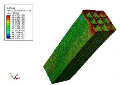
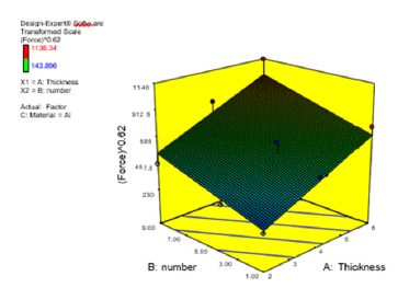
Figure 11:Effect of two parameters of number of squares and thickness on the value of force.
Optimization of transverse collision
After analyzing the data, the software defines a mathematical correlation between the absorbed energy and the force with the factors defined in accordance with Eq.1 for energy and in accordance with Eq. 2 for the force:
Material:Al(Energy)0.43=-1.56261+4.24938*Thickness+0.98 489*number+0.015386*Thickness*number-0.25233*Thickness2- 0.044567*number2
Material: St(Energy)0.43=-1.52866+3.94795*Thickness+0.89 698*number+0.015386*Thickness*number-0.25233*Thickness2- 0.044567*number2
Material: St (Force)0.62= -165.76093+110.83964*Thickness+3 5.89849*number
Material: Cu (Force)0.62=-119.19383+110.83964*Thickne ss+35.89849 * number
It should be noted that in the above equations, Thickness is the value of profile thickness and number, is the number of squares. 3D charts are presented to examine the effect of each parameter on the response. Effect of two parameters of the thickness of the profile and the number of squares on the response of the aluminum is shown in Figures 12,13. As shown in Figures 12,13, increasing the thickness of the profile, as well as increasing the number of squares, raises the value of force and absorbed energy. After analyzing the data, the maximum energy and minimum force gained in the transverse impact of the Design Expert Optimization software are listed in Table 4. As shown in Table 4, 4 solutions have been proposed for this purpose, as the most desirability of which is 0.83, in the condition where the thickness of the steel was 5.22 mm and the number of squares was 5.86 (Table 5).
Figure 12:Effect of two parameters of number of squares and thickness on the value of absorbed force.
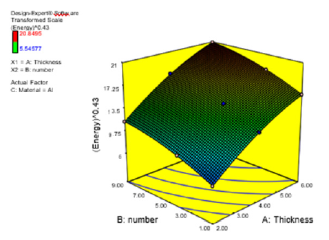
Figure 13:Effect of two parameters of number of squares and thickness on the value of longitudinal collision.
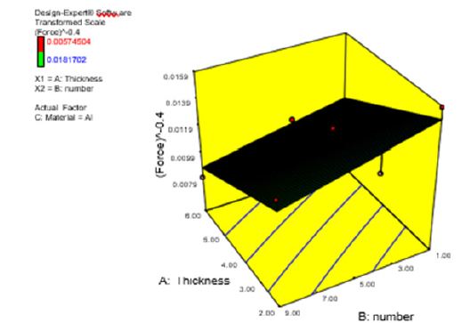
Table 4:The table recommended for the optimum conditions of the transverse impact.

Table 5:The optimum condition in transverse collision.

Figure 14:Effect of two parameters of number of squares and thickness on the value of absorbed energy of the longitudinal collision..
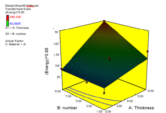
Figure 15:The optimal cross-sectional area in two longitudinal and transverse impact conditions.
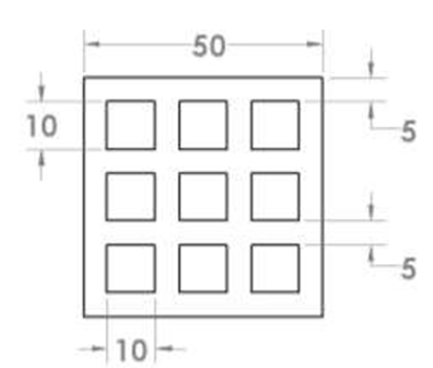
Table 6:The table recommended for the optimum condition of longitudinal collision.

Table 7:The optimum condition in longitudinal collision.

Optimization of longitudinal collision
The mathematical correlation defined by the software for
longitudinal collision is also shown by Eq.3 for energy and Eq.4 for
force:
Material: Al (Energy)0.85=+58.88500+9.11885*Thickness-
7.70242*number+3.75927*Thickness*number
Material: St (Energy)0.85= +63.62125-6.49093*Thickness
-4.48344*number+3.75927*Thickness*number
Material:Al(Force)-0.4=+0.017421-1.04055E-003*Thickness-
3.53936E-004*number+1.50174E 005*Thickness*number
Material:St(Force)-0.4=+0.018951-1.13781E-004*Thickness-
1.19584E-003*number+1.50174E-005*Thickness*number
Material: Cu (Force)-0.4=+0.013879+1.19725E-
004*Thickness-5.15863E-004*number+1.50174E-005* Thickness
* number
In the above equations, Thickness is the value of profile thickness and Number is the number of squares.
Figures 14,15 show the effect of two parameters of the thickness of the profile and the number of squares in aluminum on the response. As could be seen in these two Figures, the value of force and energy absorbed increases by increasing the profile thickness and also increasing the number of squares. For this purpose, 6 solutions are proposed, which are listed in Table 6. As shown in Table 6, 6 solutions have been proposed for this purpose, as the most desirability of which is 0.889, in the condition where the thickness of the aluminum was 6.00mm and the number of squares was 9.00. By rounding the numbers above, the optimal mode is shown in Table 5. As shown in Table 6, 7 solutions have been proposed for this purpose, with the most favorable of 0.889, with an aluminum thickness of 6.00mm and number of square of 9.00. The optimal mode is shown in Table 7.
Conclusion
This section summarizes the results obtained in order to
select the optimal scheme in which the absorption of energy is
maximized while the imposed force is minimized. Tables 4 and 6
proposed the conditions for longitudinal and transverse collisions.
The recommended priorities of the two longitudinal and transverse
collisions have been compared in Table 8. Obviously, in these
conditions the value of energy is Selected dramatically decreased
(13% of the previous conditions), while the energy absorption
value has a significant effect in the health of the occupant. Values
of the force and energy were, for choosing the optimal design plan.
There are two plans for finalization that are listed in Table 8. The
selection of aluminum has the following advantages over the steel:
A. Lower weight
B. Higher machining speed
C. Being less expensive
D. Lower machining cost
E. Resistant to corrosion
Considering the above explanations, the use of aluminum is more cost effective and more convenient. Regarding the items described in later sections, the optimal design is selected by the aluminum. This plan is described in Table 8.
Table 8:Comparison of the optimum conditions in longitudinal and transverse collisions.

References
- Keskin SA, Acar E, Güler MA, Altin M (2021) Exploring various options for improving crashworthiness performance of rail vehicle crash absorbers with diaphragms. Structural and Multidisciplinary Optimization 64(5): 3193-3208.
- Mortazavi MA, Kheradpisheh A, Asgari M (2021) A basic design for automotive crash boxes using an efficient corrugated conical tube. Proceedings of the Institution of Mechanical Engineers, Part D: Journal of Automobile Engineering 235(7): 1835-1848.
- Bhardawaj S, Sharma RC, Sharma SK (2020) Analysis of frontal car crash characteristics using ANSYS. Materials Today: Proceedings 25(4): 898-902.
- Xu P, Zhao H, Yao S, Che Q, Xing J, et al. (2019) Multi-objective optimisation of a honeycomb-filled composite energy absorber for subway vehicles. International journal of crashworthiness 25(6): 603-611
- Demirci E, Yıldız AR (2018) An investigation of the crash performance of magnesium, aluminum and advanced high strength steels and different cross-sections for vehicle thin-walled energy absorbers. Materials Testing 60(7-8): 661-668.
- Pyrz M, Krzywoblocki M (2017) Crashworthiness optimization of thin-walled tubes using Macro Element Method and Evolutiary Algorithm. Thin-Walled Structures 112: 12-19.
- Li X, Wang Y, Xu X, Cao X, Li R (2021) Energy absorption characteristics of crash box of new honeycomb core structure with foam-filled. Int J Automotive Technology 22(1): 221-230.
- Baroutaji A, Sajjia M, Olabi AG (2017) On the crashworthiness performance of thin-walled energy absorbers: Recent advances and future developments. Thin-Walled Structures 118: 137-163.
- Yang K, Xu S, Shen J, Zhou S, Xie YM (2016) Energy absorption of thin-walled tubes with pre-folded origami patterns: Numerical simulation and experimental verification. Thin-Walled Structures 103: 33-44.
- Zhang H, Zhang X (2016) Crashworthiness performance of conical tubes with nonlinear thickness distribution. Thin-Walled Structures 99: 35-44.
- Mohsenizadeh S, Alipour R, Nejad AF, Rad MS, Ahmad Z (2015) Experimental investigation on energy absorption of auxetic foam-filled thin-walled square tubes under quasi-static loading. Procedia Manufacturing 2: 331-336.
- Sun G, Fang J, Tian X, Li G, Li Q (2015) Discrete robust optimization algorithm based on Taguchi method for structural crashworthiness design. Expert Systems with Applications 42(9): 4482-4492.
- ASTM International. Committee B07 on Light Metals and Alloys (2015) Standard test methods for tension testing wrought and cast aluminum-and magnesium-alloy products (Metric). Duncombe JU (1959) Infrared navigation-Part I: An assessment of feasibility. IEEE Trans. Electron Devices ED-11: 34-39.
© 2023 Fariborz Forouhandeh. This is an open access article distributed under the terms of the Creative Commons Attribution License , which permits unrestricted use, distribution, and build upon your work non-commercially.
 a Creative Commons Attribution 4.0 International License. Based on a work at www.crimsonpublishers.com.
Best viewed in


.jpg)


 Editorial Board Registrations
 Submit your Article
 Refer a Friend
 Advertise With Us
.jpg)


.jpg)


.bmp)
.jpg)
.png)
.jpg)


.jpg)


.png)

.png)


.png)


