
- About Us
- Information
-

The Author ensures that the research has been conducted responsibly and ethically with adherence to all relevant regulations. read more..
- For Authors
- For Reviewer
- Manuscript Guidelines
- Membership
- Publication Ethics
-
- Journals
- Reprints
- e-Books
- Videos
- Policies
- Contact Us
 COVID-19
- Submissions


Full Text
Evolutions in Mechanical Engineering
Influence of Welding Regimes and Filler Metal on Weld Bead on 30CrMoV9 Steel Base Material
Svetislav Marković*
Faculty of Technical Sciences, University of Kragujevac, Serbia
*Corresponding author:Svetislav Marković, Faculty of Technical Sciences, University of Kragujevac, Serbia
Submission: October 8, 2024;Published: October 18, 2024

ISSN 2640-9690 Volume5 Issue4
Abstract
The research was aimed to determine the influence of the welding regimes and the filler metal types on the hard-faced weld bead and its Heat Affected Zone (HAZ). The welding process was performed on the plate samples (bead-on-plate test) of low-alloy steel 30CrMoV9. Five filler metals were used, four gas shielding welding wires of different chemical composition and one flux-cored wire. The welding regimes (electricity, voltage and welding speed) were varied, two regimes for each filler metal. After welding, the weld bead dimensions and hardness were measured and the bending test was carried out, as well. Based on the performed measurement and analysis, appropriate conclusions were drawn. Applied filler metal and arc energy can significantly affect the properties of weld beads and HAZ, but used base material 30CrMoV9 requires preheating and/or subsequent heat treatment.
Keywords:Welding; Hard facing; Filler material; Weld bead bending test
Introduction
Low-alloy steel is often used in the design of machine parts. When machine parts made of this steel wear out during the machine system operation, losing operational ability, it is necessary to replace or repair them. Repair of worn-out parts is carried out by hard facing, which is still one of the most important repair procedures. Hard facing is the deposition of thick coatings of hard, wear-resistant materials on a worn surface. Welding is one of the used processes to apply the hard facing layer using appropriate additional material-filler metal. It is very important to know what type of filler should be applied, as well as which welding method is the most appropriate. Also, it is necessary to know how repair welding affects the mechanical properties of the weld bead and whether the load capacity of the repaired machine part will be similar or the same as it was before failure and repair. After subsequent heat treatment (post heating), repaired hard-faced surface should have mechanical properties at the level of properties of the base material. Hard face welding on sample plates made of low-alloy steel 30CrMoV9, using different fillers and welding regimes, is considered in this paper.
Experimental Part with Results
The steel plates with dimensions of 150x80x10mm were used for hard face welding. The Base Material (BM) is the low-alloy steel 30CrMoV9 of chemical composition given in Table 1 [1]. Weld beads of various fillers were applied onto the 30CrMoV9 plates (Figure 1) by different single pass welding regimes of semi-automatic welding, using CO2 protective gas (C type [2]). Four fillers in the form gas shielding welding wire (diameter 1.2mm) and one filler as flux-cored wire (No.5) were used. The chemical composition of the fillers is given in Table 2 [3,4]. The welding input parameters, electricity, voltage and welding speed (travel speed of the welding torch) are varied for every type of filler metal. Each of the five used fillers was welded on the plate by two regimes. The welding regime parameters are presented in Table 3. Based on the values of current I, voltage U, and welding speed v, the energy supplied by the welding arc to the hard facing plate is calculated by the following equation:
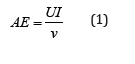
Table 1:Chemical composition of BM-low-alloy steel 30CrMoV9 (1.7707), %.

Table 2:Filler metal designation and chemical composition.

Table 3:Welding regimes.

Figure 1:Hard face welded steel plate.

Calculated arc energy, depending on welding fillers and regimes is given in Table 3. Heat input considers the influence which process efficiency has on the energy that reaches the workpiece to form the weld. HI is given by the equation:

Heat input, calculated based on arc energy considering the efficiency of 75% is given in Table 3. After welding, specimens (of width 15mm) were cut from the test plates (Figure 1), which were used to measure dimensions and hardness of the weld beads, as well as for bend testing. The measured cross-sectional dimensions of the weld beads are shown in Figure 2 and measured values (bead width, reinforcement height and penetration depth) are given in Table 4. Based on the measured weld bead dimensions, the weld penetration shape factor is:

Dilution-the area of base metal melted in relation to the crosssectional area of the bead (Figure 2) was determined using the formula:
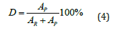
Table 4:Geometry parameters of the weld bead.

Figure 2:Cross-section of the weld bead (R-Reinforcement; P-Penetration; W-Width).

The hardness of the weld bead reinforcement area was measured, as well as the HAZ (Heat Affected Zone) hardness on different distances from the hard-faced surface (Table 5). The hardness distribution in HAZ is shown by the diagram in Figure 3. The hardness of HAZ is high near to the bead, decreasing under the hardness of the base material, on the depth of approx. (0.2 … 0.5) mm (Figure 3). The scheme of the bend test is shown in Figure 4. The weld bead is in the tension zone of the bent specimen. During the test, each specimen was bent until the first crack appeared on the weld bead. At that moment, the bending angle α (Figure 4) was registered (Table 6).
Table 5:Hardness of bead and HAZ.

Figure 3:Hardness distribution in the HAZ area.

Figure 4:Weld bead bend test.

Table 6:Bending angle corresponding to the first crack appeared on the weld bead.

Discussion
Under the applied experimental conditions and due to extremely large mass of the test plate concerning the beam mass (both reinforcement and penetration) and the high content of the base material in the beam, high values of the beam hardness with low plasticity were obtained. Furthermore, when the plates welded with higher arc energy and heat input, lower beam hardness and greater bending angles (until the appearance of the first crack) were obtained.
Based on the results from Tables 4-6, it may be concluded that:
A. Under all used regimes, a reinforcement height was higher
than the penetration depth in the base material;
B. With increasing of arc energy and heat input the width of the
beam is increasing as well;
C. In the case of welding with flux-cored wire (regimes 9 and 10),
at the same arc energies and heat inputs, a smaller penetration
depth is achieved compared to welding with gas shielding
welding wires, followed by the higher values of the weld
penetration shape factor WPSF;
D. With the increase of the arc energy and heat input, the
penetration depth also increases, whereby there is no clear
relation between the cross-section area Ap (beam penetration)
and the overall beam cross section area A;
E. Bending angle welding beam bending resistance) is increased
with increasing arc energy, heat input and bead width, but
with decreasing bead hardness.
The hardness distribution in the HAZ is given in Figure 3. Under applied welding conditions and concerning base material properties, high HAZ hardness is obtained near the bead, as well as decreasing hardness on the depth of (0.2…0.5)mm below the hardness of base material before welding.
Conclusion
The obtained results show that significant influence on the mechanical characteristics of the weld bead and the heat affected zone of the hard-faced steel 30CrMoV9 could be achieved, selecting the proper type of the welding filler and the arc energy, i.e. heat input. However, products made of this steel, with high demand in sense of resistance to crack damage, it is necessary to apply preheating and/or post heating treatment.
References
- (2000) Open die steel forgings for general engineering purposes-Part 3: Alloy special steels. British Standard, UK.
- American Welding Society (2008) Welding consumables-gases and gas mixtures for fusion welding and allied processed. (3rd edn), American Welding Society, USA, p. 14.
- AWS A5 Committee (2005) Specification for carbon steel electrodes and rods for gas shielded arc welding. ANSI/AWS, Florida, USA.
- ISO (2008) Welding consumables-wire electrodes and weld deposits for gas shielded metal arc welding of non-alloy and fine grain steels-Classification. (3rd edn), ISO, USA.
© 2024 Svetislav Marković. This is an open access article distributed under the terms of the Creative Commons Attribution License , which permits unrestricted use, distribution, and build upon your work non-commercially.
Editor In Chief


.jpg)


Signup for Newsletter

Quick Links
 Editorial Board Registrations
 Submit your Article
 Refer a Friend
 Advertise With Us
Our Recent Edition

.jpg)


Top Editors


.jpg)


.bmp)
.jpg)
.png)
.jpg)


.jpg)


.png)

.png)


.png)


Financial Support

Sponsors

Latest e-Books

Latest Video

 a Creative Commons Attribution 4.0 International License. Based on a work at www.crimsonpublishers.com.
Best viewed in
a Creative Commons Attribution 4.0 International License. Based on a work at www.crimsonpublishers.com.
Best viewed in