
- About Us
- Information
-

The Author ensures that the research has been conducted responsibly and ethically with adherence to all relevant regulations. read more..
- For Authors
- For Reviewer
- Manuscript Guidelines
- Membership
- Publication Ethics
-
- Journals
- Reprints
- e-Books
- Videos
- Policies
- Contact Us
 COVID-19
- Submissions


Full Text
Evolutions in Mechanical Engineering
Failure of Bolted Joint Under External Eccentric Loading Condition
Nagpure S1*, Jadhav TA2 and Kumar AS3
1Dept of Mechanical Engineering, India
2Senior Product Engineer, Advanced Engineering, Cummins Turbo Technologies, India
*Corresponding author:Nagpure AS, Post Graduate Student, Dept of Mechanical Engineering, India
Submission: October 03, 2018;Published: November 01, 2018

ISSN 2640-9690 Volume 2 Issue 1
Abstract
In turbocharger, there is possibility that the impeller may sometimes burst at high rotating speed due to high centrifugal forces and temperature conditions at such high speed. The occurrence of such type of failure is very less but the risk in high. Therefore, to ensure safety of end customer, a turbocharger goes through multiple tests, out of which one is containment test. In this test, the wheel is burst by rotating it beyond the maximum operating speed. In this condition, the compressor housing should be able to contain these wheel fragments within the housing. But in test data of midrange turbocharger failed in burst and containment test, one of the causes of test failure was failure of bolted joint between compressor housing and bearing housing. Hence re-designing of the bolted joint is seen as a possible method to help in compressor cover retention. These re-designed bolted joints are termed as non-axial bolted joint.
As wheel burst is time dependent impact event, explicit dynamic analysis is carried out for simulating that event. The objective is to observe effect of re-designed bolted joint in terms of stress results in explicit analysis. This paper presents a new methodology developed for explicit dynamic analysis of structure with bolted joint. The methodology is for applying bolt pretension for performing explicit analysis. Analysis on proposed model was carried out as turbocharger assembly takes large computational time. The explicit analysis results of proposed models are compared by DOE tool.
Keywords:Containment test; Impeller burst; Bolted joint
Introduction
Turbochargers are the devices most widely used in internal combustion engines to increase engine’s efficiency and power. These are operated by engines’ exhaust gas. Small units can operate up to 2,00,000 rpm. Combination of Severe conditions at such high speed may lead to turbocharger failure. As part of health and safety procedures for turbochargers, each new design must undergo through burst and containment test [1]. Chris floren has described about burst and containment in his paper in detail. The purpose of this test is to examine ability of turbocharger housing assembly to retain wheel fragments when a rotating wheel in turbocharger is burst in fragments by centrifugal action. In this test to facilitate wheel burst in compressor, it is weakened purposely and then rotated at a speed much higher than the design speed such that it would burst [2]. Cummins containment test policy describes a about containment tests for compressor and turbine housing in detail.
When weakened impeller is rotated beyond this maximum allowable speed it breaks into fragments as it is unable to hold wheel against the centrifugal forces at such high speed. There are two types of wheel failure, blade detachment and hub burst, out of which hub burst is most severe. These types of failure are examples of extreme failure in turbocharger as it destroys turbocharger. Hence it is required that turbocharger housing should hold these fragments formed by wheel burst within housing to ensure safety of costumer. The ability of compressor housing to absorb energy released during burst and hold these fragments within housing is called containment capability of turbocharger. Every turbocharger should pass burst and containment test to qualify the turbocharger as safe for customer use.
The test data of mid-range turbocharger failed in compressor containment test shows failure of bolted joint between compressor and bearing housing being one of the reasons for failure. Hence designing the joint to improve in containment and analyzing model in ANSYS is desired in this study. One way for improving in bolted joint failure is by increasing thread engagement lengths. Grimsmo et al. [3] described the failure modes in bolted joint with different bolt lengths. Tension tests were carried out on nut and bolt assemblies to verify the failure modes. Mike Guo et al. [4] described mechanism of fastened joints and numerical analyses in his paper. This study consisted of analysis of structure consisting of bolted joint in Explicit ANSYS AUTODYN solver. New methodology was developed for analyzing model with bolted joint as there are many drawbacks and limitations of explicit solver for preloading bolts. The Pugh selection method was employed for selection of methodology. The selected methodology was then used for doing explicit analysis on proposed models with different bolt orientation and different bolt lengths. Ramamoorthy et al. [5] developed finite element methodology for simulating containment test. Models with bolt orientated by different angles and bolt lengths were drawn in CREO parametric. The analysis results were studied by Minitab tool.
Methodology Development
To get insight into behavior of structure during impact or short duration high pressure loading, explicit dynamic analysis tool is used for effective simulation. It gives accurate prediction of the effect of design considerations on product or process behavior. Therefore, explicit dynamic analysis of model was performed. In many situations preloading bolts is required to achieve a steadystate condition before running a dynamic analysis. Preloading parts in explicit cannot be done as explicit solver does not have bolt pretension boundary condition. Therefore, methodology development is essential for further analysis. To understand the behavior of bolted joint in explicit dynamics, before doing analysis of actual assembly a simple geometry of bolted joint was created. The joint consists of M6 bolt of 8.8 grade and other parts as shown in Figure 1 such that it makes tapped bolted joint.
Figure 1:Geometrical 3D model of bolted joint.

Figure 2:Meshed model of bolted joint.

The meshed model is as shown in Figure 2 Meshing is an important part in ANSYS and other FEA tools as it influences accuracy, convergence and speed of solution. The required meshing for implicit and explicit solvers is different. Explicit solver requires the Physics Preference for meshing to be set to explicit. Tetrahedral elements were preferred in this model. The element quality of most of the element was near about 1. The aspect ratio was less than 5 and skewness was less than 0.5.
Analysis of bolted joint model
The pretension to be applied on bolt is calculated as per VDI 2230 guidelines which are standards used widely for bolted joint design. The required data like bolt specifications and coefficient of friction etc. for joint are selected by using these guidelines. The preload is calculated by using equation 2. By distortion energy theory the equivalent stress for bolted joint is calculated by formula given below. The pretension of 9635 N was applied on bolt for getting pre-stressed joint.
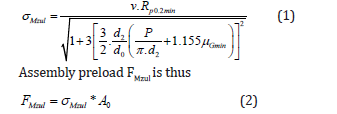
Where σMzul is comparative stress in the assembled state, P is pitch of threads, d2 is pitch diameter of bolt, μGmin is minimum coefficient of friction in the thread, RP0.2min is 0.2% yield strength of the external threads, v is utilization of the initial yield stress during tightening and A0 is minimum cross-sectional area of bolt. Static structural and dynamic analysis of bolted joint model was performed, and results were studied. The Figure 3 shows explicit analysis results of internal threads in bolted joint. As shown in graph in Figure 3 the maximum stress is dropping from 141 MPa to 80 MPa. This is analyzed by upper line in graph which represents maximum shear stress. Therefore, a methodology for preloading bolts is required which gives good results in explicit dynamic analysis.
Figure 3:Max shear stress on internal threads of bolted joint.

Methods for preloading bolt
The model used for developing methodology is as shown in Figure 1. The methods developed consisted of application of forces to create preload in joint. It was studied from the bolt pretension boundary condition used in implicit solver that forces are applied by solver on elements at middle of shank in that command. Hence the bolt is sliced at middle of bolt shank in these methods and forces are applied on these bolt faces (Figure 4-8).
Figure 4:Method 1 boundary conditions.

Figure 5:Forces direction.

Figure 6:Method 2 boundary conditions..

Figure 7:Method 3 boundary conditions

Figure 8:Method 4 boundary conditions

Method 1: Forces are applied on sliced bolt faces away from
faces so as to make compression effect. Magnitude of force is same
as bolt preload. No other boundary conditions are used in model.
Method 2: The forces applied on sliced bolt faces same as in
method 1. Displacement boundary condition is given to bolt stud
faces to allow displacement only along bolt axis.
Method 3: Compression effect is generated due to forces
applied on sliced bolt faces. These forces are same in magnitude
as bolt preload. Translational joint is used so as constrain its
movement in direction other than bolt axis.
Method 4: Forces are applied on upper face of bolt head and
lower face of stud. Forces are same in magnitude as bolt preload.
Selection of method
The results of static structural analysis on each model are listed out in table below. From result Table 1-3 it was observed that analysis results of method 1, method 2 and method 3 are showing good correlation with analysis results of bolt pretension which is baseline. The final selection of methodology was done by considering compatibility with explicit solver for ANSYS Workbench 17.1. Cause and Effect matrix was used to finalize the method. In this weightage is given to methods to get most suitable method. From Cause and Effect matrix method 1 is selected which has scored highest. This method is used for analysis of assembly to preload bolts for explicit dynamic analysis of structure.
Table 1:Static analysis results.

Table 2:Cause and effect matrix.

Table 3:Materials of parts in proposed model..

Analysis of assemblies with non-axial bolted joint
As wheel burst consists of impact of wheel fragments on compressor cover, explicit analysis tool is used in the study. To get steady state conditions in explicit static analysis was performed before explicit. During static analysis convergence issue may appear. Two main reasons for such issue are rigid body motion and residual forces. Occurrence of any one of them doesn’t solve the analysis. As Turbocharger is a big assembly having critical geometry, it makes analysis complicated and takes larger computational time. So a simple model was modeled in CREO parametric. Such model with different bolt angles and bolt lengths was drawn. The objective is to analyze effect of bolt orientation in non-axial bolted joint on stress pattern in explicit dynamic analysis.
Proposed model: The model which was designed for doing analyses is as shown in Figure 9. This model was drawn such that the joint part is same as in turbocharger as it is area of interest. Other complicated geometries were omitted as it was not having much effect on analysis results. This model reduced computational time significantly so multiple explicit analysis of models became quite easy.
Figure 9:Geometry of proposed model.

Models with different bolt orientation and bolt lengths were drawn in CREO to study effect of non-axial bolt angle on joint failure. The models with two different angles A2 and A3 were made in addition with baseline model A1 of 0° bolt orientation. Also models with different bolt lengths L2 and L3 were created along with baseline model of bolt lengths L1. The mesh model is as shown in Figure 10. The node count varies from 30,000 to 40,000 as per accuracy needed. As can be seen from node count it is less as compared to current product, so it takes less computational time. It has benefitted in analysis as there are multiple models. The skewness of most of elements was less than 0.5 which shows good element quality. Also, aspect ratio was less than 5. The material used for different parts are listed in table below. Johnson-Cook material properties of materials were used for analysis as this impact event has high strain rate. These properties are widely used to capture strain rate sensitivity of metal in dynamic processes.
Figure 10:Boundary conditions of proposed model in static analysis.

Figure 11:Velocity Boundary conditions of proposed model in dynamic analysis.

The boundary conditions applied in static structural analysis are as shown in Figure 11. The bolt preload is applied by using method selected previously by Cause and Effect matrix. The forces are applied on bolt faces to apply bolt preload of same magnitude as bolt pretension. As simulation consist of impact of inner circular part on part 1as shown in fig, explicit analysis is carried out. For explicit analysis the boundary condition of forces is drag and dropped onto explicit to apply same conditions. As it is impact event velocity of 200 m/s is given to impacting part which was decide by doing trials. To have body interaction between sliced bolts parts during impact event bonded body interaction is applied on sliced bolt parts.
Results and Discussion
Figure 12:Equivalent stress plot of proposed model.

To simulate impact event, explicit analysis is used, and static analysis was performed before explicit analysis to get steady state condition. Hence static structural and explicit dynamic analysis was carried out on nine models with bolt orientation of three angles A1, A2, A3 and three bolt lengths L1, L2, L3. Following results were observed. The static analysis result of proposed model with bolt angle A1 and bolt length L1 is shown in Figure 12. As can be seen from the equivalent (von-Mises) stress plot the stresses due to bolt preload in static structural are in conical pattern. According to VDI 2230 guidelines the stress pattern and deformation plot have conical pattern for bolted joint. The shear stresses on internal threads and bolt threads of proposed model bolted joint in static analysis are as shown in Figure 13 and Figure 14 respectively. The shear stress pattern on internal threads and bolt threads are showing maximum stress on starting threads which satisfies the fact that maximum of load is taken by starting threads of thread engagement length in bolted joint.
Figure 13:Shear stress on internal threads of proposed model bolted joint.

Figure 14:Shear stress on bolt threads of proposed model bolted joint.

Static structural analysis of all nine models was carried out followed by explicit dynamic analysis. The static results showed desired results in terms of shear stress on threads and equivalent stress pattern in bolted joint. The normalized results of shear stress on bolt threads in static and dynamic analysis are plotted as shown in Figure 15 and Figure 16. The maximum shear stress on bolt threads in static and explicit dynamic analysis showed decrease in shear stress with increasing angle of bolt orientation. The normalized results of maximum shear stresses on internal threads in static and dynamic analysis are plotted as shown in Figure 17 and Figure 18 respectively. Stresses are decreasing with bolt angle.
This decreasing trend is desired as in non-axial bolted joint the net effect of force during impact event should be less according to concept behind modeling non-axial bolted joint. The maximum equivalent stresses on bolt under head fillet are as shown in Figure 19 and Figure 20 for static and dynamic analysis respectively. As the plot shows the stresses are increasing with increasing angle. These stresses are maximum at bolt fillet area. This result value should not exceed the yield strength of bolt material. Thus, there is one limitation on angle of bolt orientation while modeling non-axial bolted joint. Angle of bolt orientation cannot be increased too much as it will cause bolt to fail.
Figure 15:Maximum shear stress on bolt threads in static analysis..

Figure 16:Maximum shear stress on bolt threads in dynamic analysis.

Figure 17:Maximum shear stress on internal threads in static analysis.

Figure 18:Maximum shear stress on internal threads in dynamic analysis.

Figure 19:Maximum equivalent stress on bolt fillet in static analysis.

Figure 20:Maximum equivalent stress on bolt fillet in dynamic analysis.

Conclusion
The methodology developed for explicit dynamic analysis of structure with bolted joint gives good results. It has overcome problem of stress relaxation. Non-axial bolts are effective in improving bolted joint failure as shear stresses on bolt threads and internal threads are reducing with increasing angle. Important factor to consider is equivalent stress on bolts’ fillet. It shows increasing trend with increasing bolt angle which limits angle in non-axial bolted joint.
References
- Chris Floren, Burst & Containment: Ensuring Turbocharger Safety, Honeywell Garrett White Paper: Burst & Containment Cummins containment test policy
- Grimsmo EL, Aalberg A, Langseth M, Clausen AH (2016) Failure modes of bolt and nut assemblies under tensile loading. Journal of Constructional Steel Research 126: 15-25.
- Mike Guo, Shujath Ali (2006) Study on Simplified Finite Element Simulation Approaches of Fastened Joints, SAE International, US.
- Ramamoorthy JM, Parikh SS, Pandian S, KasthuriRangan PS (2014) Containment simulation and validation of turbocharger housing design, Turbo Energy Limited.
- VDI 2230 Part 1 (2003) Systematic calculation of high duty bolted joints with one cylindrical bolt.
© 2018 Nagpure AS. This is an open access article distributed under the terms of the Creative Commons Attribution License , which permits unrestricted use, distribution, and build upon your work non-commercially.
Editor In Chief


.jpg)


Signup for Newsletter

Quick Links
 Editorial Board Registrations
 Submit your Article
 Refer a Friend
 Advertise With Us
Our Recent Edition

.jpg)


Top Editors


.jpg)


.bmp)
.jpg)
.png)
.jpg)


.jpg)


.png)

.png)


.png)


Financial Support

Sponsors

Latest e-Books

Latest Video

 a Creative Commons Attribution 4.0 International License. Based on a work at www.crimsonpublishers.com.
Best viewed in
a Creative Commons Attribution 4.0 International License. Based on a work at www.crimsonpublishers.com.
Best viewed in