
- About Us
- Information
-

The Author ensures that the research has been conducted responsibly and ethically with adherence to all relevant regulations. read more..
- For Authors
- For Reviewer
- Manuscript Guidelines
- Membership
- Publication Ethics
-
- Journals
- Reprints
- e-Books
- Videos
- Policies
- Contact Us
 COVID-19
- Submissions


Full Text
Examines in Marine Biology & Oceanography
Smart Collision Alerting and Collision Avoidance System for Unmanned Surface Vehicles
Vishwamithra Sunkara* and Jason R McKenna
Roger F Wicker Center for Ocean Enterprise, within the University of Southern Mississippi, USA
*Corresponding author: Vishwamithra Sunkara, Marine Research Center, 1030 30th ave, Gulfport, MS 39501, USA
Submission: August 06, 2024;Published: September 06, 2024

ISSN 2578-031X Volume7 Issue2
Abstract
Recent technological advancements have increased unmanned marine traffic worldwide. The Unmanned Surface Vehicles (USVs) have gained much attention due to their potential benefits while the research into motion planning and Collision Avoidance (COLAV) is challenging in marine environments. In this paper, we propose a smart collision alerting and collision avoidance system that can be used in both cooperative and non-cooperative marine environments. The collision avoidance in stand-on vehicles perspective is minimal in the literature. The proposed collision alerting system notifies both the give way and the stand-on vehicles for possible collision encounters, so collision avoidance maneuvers can be executed. The International Marine Organization (IMO) defined the international regulations for preventing collisions at sea (COLREGs [1]) in 1972. All marine traffic should follow COLREGs but there are instances where following COLREGs may lead to collisions. We address such scenarios and show how the proposed collision avoidance system tackles them. The proposed collision avoidance system adheres to COLREGs for both stationary and moving vehicles, but taking smart decisions when complying with COLREGs does not lead to a safe trajectory. Simulations considering realistic elliptical bounding boxes of Ocean Aero’s Autonomous Underwater and Surface Vehicle (AUSV) Triton and Research Vessel (R/V) Ken Barbor are presented.
Keywords:Unmanned surface vehicles; Collision avoidance; Collision alerts; Smart navigation; Testing & evaluation of unmanned maritime systems
Introduction
Over the last decade, there has been a great advancement of research on unmanned vehicles related to air, ground, and water environments. Unmanned marine vehicles are currently being explored in several applications like transportation, ocean explorations, environment monitoring and water pollution to name a few. With the potential for reduced costs, safety, and eliminating human involvement, maritime industry is seeing increased unmanned operations. While the air and ground traffic has always been a major concern of accidents, marine traffic accidents are also a concerning matter. Human error being the major contributing factor for many such accidents, as per statistics provided in [2], human error caused more than 80% of ship collisions [3,4]. Found that ship navigation is responsible for more than 85% of marine accidents. Furthermore, ship collisions predominantly include violation of COLREGs. With the increase in unmanned marine vehicles operations in the field, COLREGs violations and human errors can [2] cause marine vehicles accidents as there is no unified system that coordinates unmanned vehicles and manned vehicles decisions, so there is always a confusion between the vehicles as to what course should be followed. Thus, collision avoidance is critical for unmanned marine vehicles to have a safe, reliable, and full autonomous navigation [5,6].
With the latest technological advancements and sensor integration in unmanned vehicles, several collision avoidance methods are reviewed in the literature [7-13]. Depending on the environment information, global and local path planners considering the known obstacles information were developed in [14,15]. Artificial potential field [16,17], model predictive control [18-20], dynamic window [18], deep reinforcement learning [21,22], and velocity obstacles [23,24-28] are among many that are explored to develop new collision avoidance algorithms. While many collision avoidance techniques developed for unmanned vehicles in general can be used by the unmanned marine vehicles, there are certain special considerations that should be taken into account in developing collision avoidance strategies specifically for unmanned marine vehicles.
The fundamental requirement in developing the COLAV system for unmanned marine vehicles is to have a robust, universal, and safe system that adheres to COLREGs. The COLAV system should be able to avoid static and dynamic obstacles, including other vehicles. The COLAV systems in the literature [18,19,23,24] consider only few rules mentioned in the COLREGs and act in Give-way vehicles perspective. Depending on the encounter situation the role of stand-on vehicle and the other rules may be crucial in collision avoidance. There could also be situations when a stand-on vehicle may also have to avoid collision with a give-way vehicle that is not obeying the COLREGs. The collision avoidance in give-way vehicles perspective is relatively explicit and is required to act early and sufficiently. However, the stand-on vehicle’s role depends on different encounter situations. So, it is important to consider the stand-on vehicles role as well in developing the COLAV systems. Collision Alert Systems (CAS) are also discussed in the literature [25-27,29- 31] but however, they don’t make distinction between stand-on and give-way vehicles as specified in the COLREGs.
The contributions of this article include collision avoidance laws that can be used in both cooperative and non-cooperative environments utilizing both the lateral and longitudinal accelerations as control inputs of the vehicles. The effects of time delays on these collision avoidance laws are analyzed. The collision avoidance laws are designed such that COLREGs are obeyed in all encounter situations, but take smart decisions when obeying COLREGs is not an optimal solution. These collision avoidance laws are then used to architect autonomous collision alerting and collision avoidance system in both stand-on and give-way ships perspectives. This architecture uses motion information, collision cone computations and safety margins of the vehicles to define the stand-on and the give-way ships action responsibility based on the collision alert levels. Simulations validating the smart collision alerting and collision avoidance architecture, and the proposed collision avoidance laws are also presented. This article is organized as follows. Section 2 presents the collision avoidance system which describes the collision avoidance laws in both cooperative and non-cooperative environments, the effects of time delays on collision avoidance laws are analyzed, and the COLREGS are addressed using the collision cone approach. Section 3 presents the collision alerting system by defining the collision cone computations. Section 4 presents the integrated architecture of collision alerting and collision avoidance systems. Simulations and experimental results are presented in Section 5, and Section 6 concludes.
Collision Avoidance System
Collision avoidance conditions
In this section, we present the engagement geometry between two vehicles to review the collision cone concept [5] followed by the collision avoidance laws. Using the collision cone approach, we present collision and collision avoidance conditions which are used to propose collision avoidance laws. Consider the engagement geometry between two elliptical shaped objects A and B as shown in (Figure 1). The Line-Of-Sight (LOS) is defined as the line (CACB) joining the centers CA and CB of the two objects. Without loss of generality, points CA and CB can be taken as the center of mass of the objects A and B respectively. Here, objects A and B are considered to be moving with speeds VA and VB, acting at heading angles αA and αB respectively. The kinematic equations of this LOS engagement are as follows:
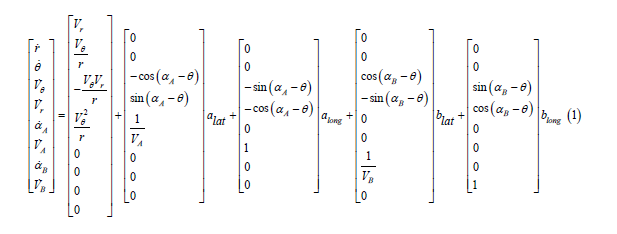
Figure 1:Engagement geometry between objects A and B.

Here, the range and the bearing of the LOS are represented by r and θ respectively, while the relative velocity components (of B with respect to A) are represented by Vθ and Vr respectively that are normal to and along CACB. Here, alat and aalong are the lateral and longitudinal accelerations of the object A respectively, while blat and blong are the lateral and longitudinal accelerations of the object B. The lateral and longitudinal accelerations alat, aalong and blat, balong are the control inputs of objects A and B respectively. This implies that the objects A and B can use lateral and longitudinal accelerations in the guidance laws, where lateral accelerations make the objects change their orientations, while the longitudinal accelerations cause the objects to increase or decrease their speeds.
In [5], the collision cone is defined as the set of all possible heading angles that will cause object A and B to collide with each other. In relative velocity vector space, two objects A and B are said to be on collision course, if their relative velocities belong to a specific set that is encapsulated by a scalar quantity y defined as
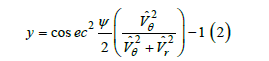
where ψ is the vertex angle of cone ϵ3 and Vˆθ and ˆVr are the relative velocity components of the angular bisector of this cone. The cone ϵ3 as shown in Figure 1 can be formed by totally containing objects A and B on the opposite sides of the vertex O of the cone ϵ3. Vˆθ is the relative velocity component normal to the angular bisector XX′ while Vˆr is the relative velocity component along this angular bisector.
Using the equation (2), the collision cone can now be defined as the region in (Vˆθ , Vˆr) space for which y<0 and Vˆr<0 is satisfied. This is the collision condition which physically interprets that the relative velocity vector of the object A is lying inside the collision cone and thus is in collision course with the object B. When the condition y=0 and Vˆr <0 is satisfied, the relative velocity is lying along the boundary of the collision cone and at the time of closest approach both the objects graze each other. The relation between the relative velocity components of LOS (CACB) and the angular bisector (XX′) of cone ϵ3 is given below
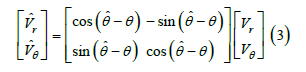
Here note that when objects A and B are both circular objects, CACB and XX′ coincide with each other as θˆ<θ and thus Vˆθ=Vθ and Vˆr=Vr. The Time of Closest Approach (TCA) when the points CA and CB are the closest to each other is given as
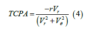
Above equation can also be represented as the ”time-to-go” till collision occurs. Here note that when objects are approaching each other Vr < 0 i.e., the range between points CA and CB is decreasing with time and thus tm>0 . Considering that the objects A and B are moving with constant velocities, both the necessary and sufficient conditions for collision to occur is y<0 and Vˆr <0 [5] at a time t≤tm. If the objects A and/or B are moving with varying velocities, then a necessary condition for collision to occur is that at the instant of closest approach, y<0 holds, i.e., y(tm)<0. This implies that the velocity vector is still lying inside the collision cone even at the closest point of approach and thus both the objects collide with each other. The sufficient conditions for objects A and B to avoid a collision with each other are (1) y<0 and Vˆr>0∀t ≤ tm , or (2) y≥0∀t ≤ tm . Thus, the control inputs alat, along, blat, and blong in (1) should be such that the above sufficient conditions are satisfied to avoid collision. Driving y in (2) to a non-negative value implies that the velocity vector is being driven from interior of the collision cone to the boundary/outside.
Co-operative collision avoidance law
In this section, we determine a guidance law for cooperative collision avoidance that drive y(t) from an initial negative value to a non-negative reference value ω ≥ 0 . The control inputs in (1), alat, along, blat, and blong which are the lateral and longitudinal accelera tions of objects A and B respectively are derived that cooperatively drive the relative velocity vector from inside the collision cone to outside the collision cone.
Consider the Lyapunov function as below:
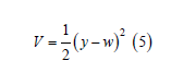
where y is defined in (2) and w is a non-negative reference input. Now, we design a state feedback control law that makes the derivative of (5) negative definite, which is equivalent to driving y(t) to w. The time derivative of y is as follows:
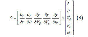
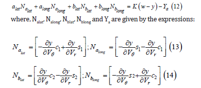
wherein, the partial derivatives are found to be the following:
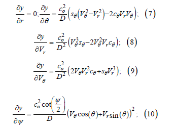
For simplicity, following shorthand notation is used:
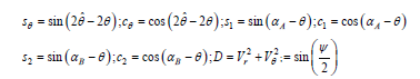
Here, as the acceleration magnitudes alat, along, for object A and blat, and blong for object B are considered as the primary inputs used to drive y(t) to a non-negative reference value ω ≥ 0 , these acceleration magnitudes will ensure that V < 0 holds. The derivative of the Lyapunov function V is given below:
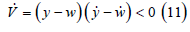
Above inequality states that the derivative of Lyapunov function V is negative definite and in turn shows that the closed loop system is globally asymptotically stable. Substituting (6) in (11), the control inputs alat, along, for object A and blat, and blong for object B are chosen such that V = −2KV is satisfied, where K>0. Doing so, we eventually obtain
+Any pair of lateral and longitudinal accelerations of objects A and B that satisfy the equation (12) will ensure that the derivative of Lyapunov function is negative, and these accelerations will cooperatively drive y(t) to the non-negative reference input w. Note that, there can be multiple combinations of lateral and longitudinal accelerations of objects A and B that satisfy (12). A candidate solution can be the following:
Any positive value of the gain K will guarantee that the lyapunov
function V(t) decays exponentially to zero satisfying V = −2KV , and
thus y(t)→w. However, the gain K should be chosen large enough
that V comes to an ϵ bound of zero, within time t≤tm. This can be
achieved if 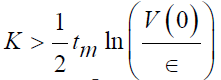 . The large the gain K, smaller the achievable
ϵ. However, large K can lead to actuator saturation because of
larger acceleration commands.
. The large the gain K, smaller the achievable
ϵ. However, large K can lead to actuator saturation because of
larger acceleration commands.
In (12), lateral and longitudinal accelerations of objects A and B are such that the lateral accelerations acts to change the heading angles of the objects, while longitudinal accelerations acts to increase or decrease the speeds of the objects. The objects can also use both lateral and longitudinal accelerations to change both the speed and orientations altogether. The weighing gains Ka,blat can be chosen appropriately to prioritize changing the orientation and the speed of the object. The objects with more manueverability in changing speeds can choose Ka,blat>1, and objects more maneuverable in changing orientations can choose Ka,blat< 1. One can also choose to solely use lateral or longitudinal accelerations as control inputs in which case Ka,blat= 0. Under non-cooperative framework, considering the object A is acting individually to drive y(t) to non-negative reference input w, equation (12) can be solved for alat,long by choosing blat,long=0 and vice-versa (Figure 2).
Figure 2:(A) COLREG categorization based on bearing angle. (B,C, and D) Encounter situations of own-ship and target-ship as mentioned in COLREGs.

Addressing COLREGs using the collision cone approach
Here we embed COLREGs into the collision cone approach. As mentioned in COLREGs, various encounter situations between the target-ship and the own-ship depend on the bearing angle as shown in the Figure 2. The International Maritime Organization in 1972 proposed COLREGs to define how maritime vehicles should act in various situations in marine environments to navigate safely without collisions in presence of other oncoming marine vehicles [1]. These laws, which were created for manned surface vehicles, must be re-considered when creating course planning and collision avoidance systems for USVs.
COLREGs are made up of 38 rules divided into five sections.
Part B, “Steering and Sailing Regulations,” comprises rules 4-19
for dealing with collision avoidance scenarios. Rule 7 says to use
onboard measurement devices (Compass, RADAR, LIDAR, and AIS)
in estimating the risk of collision to ensure safe navigation. Rule 8
determines the actions to be taken to avoid collisions in instances
of possible collision. In designing the collision avoidance strategies
and algorithms for USVs the rules 8 and 13 - 17 are most relevant
as given below:
Rule 8 - Action to avoid collision: This rule states to take actions
by changing course and/or speed to avoid collision, if necessary
be large enough to be readily apparent to another vehicle. The
actions taken to avoid collision shall be such as to result in passing
at a safe distance. It also states that changing course alone may be
the most effective action when sufficient sea room is available.
Rule 13 - Overtaking: This rule states that a vessel is overtaking
another vehicle if the overtaking vehicle is approaching the
overtaken vehicle from a direction more than 22.5o abaft her beam.
It is also stated that if the vehicle is in any adoubt as to whether
she is overtaking, she shall assume that this is the case and act accordingly.
However, it is not mentioned here as to which side the
overtaking vehicle shall overtake the other vehicle.
Rule 14 - Head on: When two vehicles are approaching each
other reciprocal or nearly reciprocal, they are said to be in a headon
situation, and thus both vehicles shall change their course to
starboard to avoid collision with each other. It is also mentioned
that if one vehicle is in any doubt as to whether such a head-on situation
exists, it shall assume that it does exist and act accordingly.
Rule 15 - Crossing: When two power-driven vehicles are
crossing so as to involve risk of collision, the vehicle which has the
other on her own starboard side shall keep out of the way and shall,
if the circumstances of the case admit, avoid crossing ahead of the
other vehicle.
Rule 16 - Action by give-way vehicle: Every vehicle which is
directed to keep out of the way of another vehicle shall, so far as
possible, take early and substantial action to keep well clear. A vehicle
is called a give-way vehicle when this is the vehicle which is
deemed to change its course and/or speed in a crossing situation,
while the other vehicle which is deemed to stay on its course and
not alter is called a stand-on vehicle.
Rule 17 - Action by stand-on vehicle: This rule states that the
stand-on vehicle shall keep its course and speed to avoid collision in
such situation. However, the stand-on vehicle can react by changing
its course and/or speed in appropriate situations when the giveway
vehicle is not taking any actions to avoid collision. From the
perspective of the own vehicle, deciding when to execute which action
is dependent on the relative bearing of the approaching target
vehicle which must be avoided is shown in Figure 2. The COLREG
rule that has to be followed is decided based on the bearing angle
(θ) lying in one of the regions B, C, and D in Figure 2. The collision
cone is computed for these encounter situations and (12) can be
used to drive y(t) to a desired reference value to avoid collisions.
The non-negative reference ω can be chosen as per the COLREG
rule 8 to keep a safe distance at the time of closest approach of both
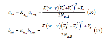
the vehicles. When two vehicles are in an head-on situation and
cooperating with each other, then equations (16) and (17) can be
used to cooperatively avoid the collision as per the rule 14 (Figure
3).
Figure 3:COLREGs and the collision cone approach conflicts.

As per Rules 13 and 14, both the vehicles that are on collision course with each other shall change course to starboard to avoid collision. But, there are situations when complying to COLREGs is not an optimal decision. Rules 13 and 14 conflict with the collision cone approach to turn to starboard to avoid collision. Consider the crossing and head-on situations depicted in Figure 3 where the target ship and the own ship along with their velocity vectors are colored in blue and green respectively. Collision cone of the own ship relative to the target ship is colored red with dashed black line as the center of it. As per the rule 13, the own ship has to turn to starboard, in which case the velocity vector has to be driven to the farthest boundary of the collision cone. But, doing so will increase the risk of collision until the velocity vector is at the center of the collision cone. Thus, driving the velocity vector to the closest boundary of collision cone is the optimal solution. However, if one of the vehicles is not using the collision cone approach then the other vehicle is bound to follow COLREGs. In such cases where the velocity vector has to be driven to the farthest boundary of the collision cone to comply with COLREGs, the gain K in (16) and (17) has to be chosen appropriately. Choose a negative gain to drive the velocity vector to the center of the collision cone. When the velocity vector is at the center of the collision cone, y(t)=-1. Then change the gain K to a positive value to drive the velocity vector outside the collision cone. Please note that y ranges between [-1 1] as per the equation (2).
Collision avoidance system architecture
Here the architecture of collision avoidance system is presented as shown in Figure 4. The collision avoidance system takes the input from collision alerting system and generates appropriate safe trajectories by computing the necessary control inputs. The collision alerting system and its architecture are presented in Section III. The collision avoidance system process the motion information of the own ship and the target ship, situational awareness of the own ship, alerts generated by the collision alerting system and the COLREGs to apply the appropriate collision avoidance laws as described in subsections A and B. A local safe trajectory is only generated in presence of a collision risk using the collision cone approach adhering to COLREGs. Otherwise the global nominal trajectory is used to generate the appropriate control inputs. Note that the collision cone approach is a reactive local collision law and hence is activated in presence of a collision prediction. The control inputs are computed in the process of generating a safe trajectory and are passed to the own ship actuators to change the vessel dynamics. Change in vessel dynamics changes the LOS kinematics which are used to compute y(t). The error difference between reference value (w) and y(t) is passed to the local path planner until the error is minimized.
Figure 4:The collision avoidance system architecture.

Collision Alerting System
In this section, we discuss the collision alerting system algorithm followed by the collision alerting system architecture.
Collision alerting system algorithm
In this section, we determine collision alerting system algorithm utilizing the collision cone approach. We present collision alerting system in both give-way and stand-on ships perspectives. The encounter stages of two vehicles that are on collision course with each other can be divided into four stages Figure 5. The safety margin of a vehicle is defined as the angle difference between the closest collision cone boundary and the velocity vector of the vehicle. Using the safety margin and the turn rate of the vehicle, turning ability of the vehicle to steer the heading angle from the collision cone to the outside within TCPA time span are determined. Computation of safety margin and usage are discussed in later part. The four encounter stages of two oncoming vehicles described below:
Figure 5:Encounter stages of two vessels that are on collision course with each other.

Stage 1: The vehicles are not on collision course with each other.
Velocity vectors of each are outside the collision cone. Thus no
risk of collision exists. Both the vehicles have unrestricted action.
However, as per the Rule 8, a safe distance should be maintained by
both the vehicles at the time of closest approach.
Stage 2: The vehicles are on collision course with each other.
This implies that y(t) is negative and the velocity vectors of each vehicle are lying inside the
collision cone. Depending on the encounter situation in Figure 2,
the give-way and the stand-on ship should behave accordingly. The
stand-on ship should maintain her speed and course, while the
give-way ship is required to act to eliminate the collision.
Stage 3: One of the vehicles is not complying with COLREGs
and is increasing the risk of collision. y(t) decreases from its initial
negative value at the time of collision detection in stage 2 and
the collision cone keeps increasing. The own ship has reached its
safety margin limit and may lose the capability to avoid collision
alone in future. In this situation, the own ship may react to avoid
collision complying to COLREGs as per its role. The give-way ship
must act to avoid collision, while the stand-on ship may also act to
avoid collision. As suggested in COLREGs, a substantial turn can be
taken in the most effective direction to steer the vehicle away from
the collision path.
Stage 4: Risk of collision is high and the vehicles will collide
if no action taken. This is an immediate danger situation. In this
stage, both the vehicles have surpassed their safety margins and
thus have lost the capability to avoid collision individually. Now
both the vehicles shall cooperatively act to avoid imminent collision
as it cannot be eliminated by either of the vehicles action alone.
Each vehicle shall take appropriate actions cooperatively to change
course and/or speed to avoid imminent collision.
Each stage in Figure 5 can be classified into four alert levels
([6]) as below:
a) Safe: This alert level indicates that there is no risk of collision
and both the vessels have unrestricted action obligation. A safe
distance can be maintained at the closes point of approach and
thus marked green in Figure 5. This level corresponds to situation
1 in Figure 5.
b) Caution: Stage 2 corresponds to this alert level which indicates
that a risk of collision exists between the own ship and
the target ship. In this situation, give-way ship may act to avoid
possible collision while the stand-on ship shall maintain her
course and speed. This level is marked yellow in Figure 5 as
there is a risk of collision and both the vessels need to pay attention
to each other’s future behaviours.
c) Warning: This alert level corresponds to stage 3 in Figure 5 indicating
that one of the vessel is not complying with COLREGs
and is increasing the risk of collision. The action obligation for
both the vessels in this situation is to take necessary actions to
avoid collision. In this situation the own ship has reached its
safety margin limit to avoid collision as the target ship is not
complying with COLREGs. Thus depending on the encounter
situation, the give-way ship must take action to avoid collision
while the stand-on ship is permitted to take necessary actions.
Thus this level is marked orange in Figure 5 as the risk of collision is high as the own ship has reached its safety margin.
d) Alarm: This is a dangerous situation where an imminent risk of collision exists as both the vessels have surpassed their safety margins and thus the collision can only be avoided if both the vessels cooperate with each other. This level is marked red in Figure 5. The flow chart describing the determination of alert levels for a USV is shown in Figure 6. This algorithm determines the collision alert levels for any encounter situation and then the corresponding actions that are allowed by the own ship are concluded. The own ship and the target ship motion information are used to decide the role of the own ship as either the give-way ship or the stand-on ship based on the COLREG categorization as shown in Figure 2. Once the roles of the own ship and the target ship are decided, then collision prediction is made using the motion information and collision cone computations. A safe alert is generated when no collision is predicted and thus both the own ship and the target ship are unrestricted to take any actions. In this case, the path planner does not apply any collision avoidance laws and thus a global path is tracked by the own ship. In case of a collision prediction, it is checked if the target ship is communicating and is aware of the encounter situation. If the target ship is communicating but is not aware of the encounter situation, then it is assumed that the own ship informs the target ship of the existing encounter situation.
Figure 6:Collision alerting system algorithm.

Figure 7:Safety cone representation at ϕ<ϕs (A) and ϕ=ϕs (B).

The motion information and the collision cone computations are used in computing the safety margin of the own ship. Changing the course of own ship is the most commonly used way to avoid collision. However, the own ship may use lateral and longitudinal accelerations to change the speed and longitudinal acceleration limits. Assuming the maximum lateral acceleration limit of the ship produces ϕm angle orientation per second, then within t=tm time span the own ship has the capability to orient the ship at ϕs=ϕm∗t angle. Using ϕs, a safety cone can be constructed as shown in Figure 7. Here, cone in red is the collision cone while the cone with green dashed lines is the safety cone with the velocity vector of the own ship represented by green arrow. The safety margin of a ship (ϕ) is defined as the angle between the heading angle of the ship and closest boundary of collision cone as shown in Figure 7. As can be seen in Figure 7, though velocity vector is inside the collision cone it still has the capability to drive the velocity vector outside the collision cone as the safety margin ϕ<ϕs. When the angle ϕ= ϕs, the own ship is at its safety margin limit. For ϕ>ϕs, the own ship will not be able to steer it outside the collision cone within time TCPA even by applying the maximum lateral acceleration.
The safety margin of a ship can be divided into three levels High, Medium, and Low using the maximum turn angle of the ship in TCPA time span. If ϕ=25%ϕs, the maneuvering capability of the own ship to steer the ship outside the collision cone is high, indicating that the own ship can exit the collision course within time TCPA by applying maximum lateral acceleration. Similarly, ϕ=75%ϕs and ϕ=100%ϕs the maneuvering capability of the own ship to steer the ship outside the collision is medium and low respectively. At ϕ>ϕs, the collision cone and safety cone boundaries overlap and thus indicate that even by applying the maximum acceleration limits, the own ship will not be able to steer the ship outside the collision cone within time TCPA. The levels of safety margin are used in the collision alerting system to determine the collision alert levels based on the situational awareness of the own ship and the target ship as shown in Figure 6. When the target ship is not communicating it is assumed that it is not aware of the encounter situation and thus comparing the angles ϕ and ϕs, the collision alerts are determined accordingly as Warning and Alarm if the safety margin is high and medium, and low respectively.
After the communication status of the target ship is determined, it is checked whether the target ship is complying with the COLREGs as per the existing encounter situation or not. If the target ship is complying with the COLREGs then a Caution alert is generated. Depending on the role of the own ship as shown in Figure 5., the necessary action is taken. If the target ship is not complying with the COLREGs, the safety margin angle ϕ is computed and comparing the angle ϕ with ϕs, the corresponding collision alert is determined accordingly as Caution, Warning, and Alarm if the safety margin is high, medium, and low respectively.
The alert levels generated by the collision alert system are used by the path planners to compute the appropriate control inputs to generate the safe trajectory. The algorithm as shown in Figure 6 is from an own ship perspective which depending on the encounter situation could be the give-way ship or the stand-on ship. Based on the encounter situation and the collision alert, the path planner reviews the COLREGs and collision avoidance laws to generate the appropriate control inputs.
Integrated Collision Alerting and Collision Avoidance System Architecture
Figure 8:Integrated collision alerting and collision avoidance system.

Here we describe the integrated collision alerting and collision avoidance system architecture as shown in Figure 8. The collision alerting system takes the input from the on-board sensors and runs it through each module in the system performing necessary computations to determine the collision alert levels. Based on the collision alert levels, the actions of the own-ship and the target ship are determined which are used by the collision avoidance system to generate a safe trajectory. The appropriate control inputs are used by the actuators of the own ship to change the course and/or speed to avoid collision. Unmanned maritime vehicles are equipped with sophisticated sensor suite that helps the vehicle in localization and perception of self and the surrounding environment. Most common on-board sensors are AIS, LIDAR, RADAR, DVL and weather stations. These sensors can be used to obtain the target ship and the own ship motion information, and environment perception. The target ships and the obstacles can be stationary and/or dynamic. The potential obstacles other than traffic vessels could be buoys and ocean garbage. The proposed collision alerting system treats these obstacles as vessels and applies COLREGs equivalently. In this case, we assume that the own ship has specific set of sensors that can detect and predict these obstacles motion information. We assume that the own vessel knows the control inputs saturation limits. Most unmanned maritime vehicles use rudders and propellers as the control actuators. Thus, the safety limits of the ship like the maximum rudder angle, RPM limits of the propeller, heading angular rate limits should be known by the own ship. These safety limits are used in assessing the turning ability of the ship to determine the collision alert levels as discussed in above section. When the target ship is detected by on-board sensors on the own ship, the information from Sensing, Environment Perception and Own State Prediction modules in integrated architecture shown in (8) decides the role of own ship as either the give-way ship or the stand-on ship.
Knowing the role of the own ship and motion information of own ship and the target ship, the collision cone is computed. The collision cone is defined as the set of all heading angles of the own ship that cause collision with the target ship. The set of all these heading angles are encapsulated in quantity y [5]. The parameters y and the time of closest approach TCPA can be computed using (2) and (4) respectively. The collision is predicted if the collision condition y<0 and Vr <0 is satisfied. The impact of collision can be estimated by the value of y. More negative the value of y and smaller the TCPA is higher is the impact of collision.
The COLREGs, safety margin (ϕ), y(t) and TCPA are used in analyzing the encounter situation of the own ship and the target ship. Depending on the situation and analyzing the COLREGs, appropriate collision alerts are issued which can be used by the path planner and/or the navigator to take necessary control actions to avoid collision. The path planner utilizes COLREGs and the collision avoidance laws in section?? in computing the appropriate control inputs (alat, along, blat, blong). These control inputs are used by the actuators of the own ship to change the dynamics of the own ship until the collision is avoided.
Simulations
Simulation results considering 14, 15, and 17 COLREG rules are presented in this section demonstrating the smart collision alerts and collision avoidance system. The realistic elliptical bounding boxes for each vehicle are considered in the simulations. Ellipses make a good bounding box for marine vehicles considering their shape increasing the amount of free space for safe trajectories to lay compared to circles. The dimensions of the bounding boxes for vehicles A and B are taken from the actual dimensions of R/V Ken Barbor and Oceanaero’s Triton AUSV respectively. The maximum turn rate of vehicle A and B are assumed to be 30(deg/s) and 15(deg/ s) respectively which are produced when the saturated accelerations aA,max and aB,max are applied by each vehicle respectively. For the brevity, we color coded the vehicle A in blue, vehicle B in pink, the tracks of the vehicles as per the alert levels in Figure 6. The collision cone boundaries are colored in red, safety cone boundaries in green, and the heading angles of the vehicles are marked by black arrows.
Figure 9:Tracks of vehicles A and B for Rule 14 case simulation.

Figure 10:y,Vr, acceleration magnitudes (alit, blat), and heading angles (α, β) of vehicles A and B respectively.

a) Rule 14 - Head on: Here the vehicle A is considered to be at an initial position (xA,0, yA,0)=(0m, 0m) moving with vA=2(m/s) speed at an initial heading angle α=45deg. While, the vehicle B is starting from (xB,0, yB,0)=(20m, 20m) with speed vB=1.8(m/s) at an initial heading angle β=−135deg. The initial engagement of the vehicles are chosen such that they are on head-on collision 426 course with each other, but however, each vehicle realizes it based on the detection sensors on-board the vehicles. Here, in this case, vehicles A and B are on head-on collision course and we assume that each doesn’t react to avoid collision until they are at stage 4 encounter. When vehicles are at stage 4 severity, each vehicle should cooperatively react and follow the safe trajectory to avoid collision. In Figure 9, at time=0 the heading angle of vehicle A (in blue) is inside the collision cone boundaries represented by red lines while the heading angle is represented by a black arrow. The heading angle of the vehicle B (in pink) is also inside the collision as defined by the initial engagement of vehicles A and B. From Figure 10, y is negative and vr is also negative satisfying the collision condition. Since the vehicles are on head-on collision course with each other, they belong to the encounter stage 2 with a warning alert, but at time=4.277s, as can be seen from the Figure 9, the collision cone boundaries almost overlap with safety cone boundaries of vehicle B, implying that even by applying the max turn rate, the vehicle B will not able to drag the heading angle outside the collision cone. Moreover, the heading angle of vehicle A is also still inside the collision cone at this severity of encounter stage 4 which is alarming as the vehicles are close to each other and have to work cooperatively to avoid collision. This puts the vehicles in stage 4 with Alarm alert level. At this stage, vehicles A and B applied cooperative accelerations alat and blat as shown in Figure 10 by changing the heading angles α and β as in Figure 10. Upon applying the control inputs and cooperatively pulling the heading angles outside the collision cones as shown in Figure 9 at time=6s. and also indicated in terms of y>0 in Figure 10, the vehicles A and B are at the closest approach. Here, a reference of y=0.2 was chosen and hence is y=0.2 at time=6s. Beyond this time the vehicles are not on collision course and hence are at encounter stage 1 with a safe alert level. The alert levels are shown by color along the tracks of the vehicles in Figure 9.
b) Rule 16 - Action by give-way vehicle: Consider the engagement situation as shown in Figure 11, where vehicle A (in blue) is stand-on vehicle while B (in pink) is a give-way vehicle classified as per the COLREGs. Depending on the detection sensors onboard each vehicle, each vehicle recognizes the other vehicle when they are at a certain distance apart from one another. Here the vehicle B is a Give-Way vehicle while the vehicle A is a Stand-On vehicle. We assume that in this case the vehicles realize their encounter situations at time=1.694s. At this time, the vehicles are communicating and following the COLREGs so a caution alert is received by the vehicle B., and hence starts applying the lateral acceleration to avoid the collision. As can be seen from the Figure 11 at time=1.694s, the heading angle of the vehicle B is lying towards the left half of the collision cone boundaries, so turning to the port side and crossing ahead of the stand-on vehicle yields optimal collision avoidance effort in terms of the control input. However, as per the COLREG Rule 15 the give-way vehicle should avoid crossing ahead of the stand-on vehicle. This is a COLREG conflict where adhering to COLREGs is not an optimal solution. For a man-in the-loop architecture, the operator can choose whether to follow the COLREGs or to follow the optimal solution after a collision alert is raised. If COLREGs are to be followed to avoid crossing ahead of the stand-on vehicle, the explanation provided in the Sub-Section C of Section II after the Rule 17. In this simulation, the optimal solution is chosen so the give-way vehicle avoids collision by driving the velocity vector of the vehicle to the closest collision cone boundary. At the time=6s, the vehicles are not on collision course any more as can be seen from the Figure 12, the y is a non negative number at time=6s. In this scenario, the vehicle B after avoiding collision with the vehicle A applies a proportional control to get back to its original heading angle which is 90deg. This can be seen from the Figure 12, where the heading angle of vehicle B is 90deg at time=0s, deviates to 105deg at time=5s, and then back to 90deg at 10s. The changes in applied acceleration can also been from the Figure 12.
Figure 11:Tracks of vehicles A and B for Rule 16 case simulation.

Figure 12:y,Vr, acceleration magnitudes (alat, blat), and heading angles (α, β) of vehicles A and B respectively.

c) Rule 17 - Action by stand-on vehicle: In this case, consider the engagement at time=0s in the Figure 13 where as per the COLREGs, the vehicle A is a stand-on vehicle and the vehicle B is a give-way vehicle. Here we assume that the vehicle B is not communicating and following the COLREGs with the vehicle B for the whole duration. The vehicle A doesn’t take any action until stage 3 and starts applying lateral acceleration at time=2s to avoid collision. As can be seen from the Figure 14, the vehicle B didn’t change its orientation while the vehicle B deviated its heading angle from 180deg at time=0s to 196deg at time =8s. The alert levels along the track can be seen from the Figure 13.
Figure 13:Tracks of vehicles A and B for Rule 17 case simulation.

Figure 14:y, Vr, acceleration magnitudes (alat, blat), and heading angles (α,β) of vehicles A and B respectively.

Conclusion
In this paper, we presented different scenarios of marine vehicles including the autonomous vehicles on how to avoid collisions with proper alerts considering the properties of the vehicles. A cooperative collision avoidance system is developed that can be used by the marine vehicles in cases of stage 4 encounter situations where neither vehicle can avoid collision independently. The proposed cooperative collision avoidance system can also be used independently in situations where needed and also can use lateral and longitudinal accelerations as control inputs to avoid collisions depending on the type of the vehicle. A collision alert system is developed which takes into account the collision cone methodology, and the collision avoidance system to generate the appropriate alerts that can be used by the autonomous vehicles as well as the manual operators. The simulations of several scenarios verify the effectiveness of the collision alerting and collision avoidance system.
References
- International Maritime Organization (1972) COLREGs—International Regulations for Preventing Collisions at Sea.
- He Y, Jin Y, Huang L, Xiong Y, Chen P, et al. (2017) Quantitative analysis of COLREG rules and seamanship for autonomous collision avoidance at open sea. Ocean Eng 140: 281-291.
- Wrobel K, Montewka J, Kujala P (2017) Towards the assessment of potential impact of unmanned vessels on maritime transportation safety. Reliab Eng Syst Saf 165: 155-169.
- Wu B, Cheng T, Yip TL, Wang Y (2020) Fuzzy logic based dynamic decision-making system for intelligent navigation strategy within inland traffic separation schemes. Ocean Eng 197: 106909.
- Chakravarthy A, Ghose D (1998) Obstacle avoidance in a dynamic environment: A collision cone approach. IEEE Transactions on Systems, Man, and Cybernetics-Part A: Systems and Humans 28(5): 562-574.
- IMO (2007) Adoption of the revised performance standards for Integrated Navigation Systems (INS). Resolution MSC 83/23/Add.3-ANNEX 30. IMO, London.
- Fujimura K (1991) Motion planning in dynamic environments. 1st (edn.), Springer-Verlag, USA, 13: 178
- Hwang YK, Ahuja N (1992) Gross motion planning—A survey. ACM Comput Surv 24(3): 219-291.
- Latombe JC (1991) Robot motion planning. Netherlands.
- Huang Y, Chen L, Chen P, Negenborn RR, Gelder PHAJM (2020) Ship collision avoidance methods: state of-the-art. Saf Sci 121: 451-473.
- Statheros T, Howells G, Mcdonald-Maier K (2008) Autonomous ship collision avoidance navigation concepts technologies and techniques. J Navig 61: 129-142.
- Tam C, Bucknall R, Greig A (2009) Review of collision avoidance and path planning methods for ships in close range encounters. J Navig 62: 455-476.
- Vagale A, Oucheikh R, Bye RT, Osen OL, Fossen TI (2021) Path planning and collision avoidance for autonomous surface vehicles I: A review. Journal of Marine Science and Technology 26: 1292-1306.
- Polvara R, Sharma S, Wan J, Manning A, Sutton R (2018) Obstacle avoidance approaches for autonomous navigation of unmanned surface vehicles. J Navig 71: 241-256.
- Wang N, Gao Y, Zheng Z, Zhao H, Yin J (2018) A hybrid path-planning scheme for an unmanned surface vehicle. In 8th International Conference on Information Science and Technology, pp. 231-236.
- Xue Y, Clelland D, Lee BS, Han D (2011) Automatic simulation of ship navigation. Ocean Eng 38(17-18): 2290-2305.
- Lyu H, Yin Y (2018) COLREGS-constrained real-time path planning for autonomous ships using modified artificial potential fields. J Navig 72(3): 588-608.
- Eriksen BOH, Wilthil EF, Flaten AL, Brekke EF, Breivik M (2018) Radar-based maritime collision avoidance using dynamic window. IEEE Aerosp Conf Proc 2018, pp. 1-9.
- Johansen TA, Perez T, Cristofaro A (2016) Ship collision avoidance and COLREGS compliance using simulation based control behavior selection with predictive hazard assessment. IEEE Trans Intell Transport Syst 17(12): 3407-3422.
- Xie S, Garofano V, Chu X, Negenborn RR (2019) Model predictive ship collision avoidance based on Q-learning beetle swarm antenna search and neural networks. Ocean Eng 193: 106609.
- Zhao L, Roh M (2019) COLREGs-compliant multiship collision avoidance based on deep reinforcement learning. Ocean Eng 191: 106436.
- Zhang X, Wang C, Liu Y, Chen X (2019) Decision-making for the autonomous navigation of maritime autonomous surface ships based on scene division and deep reinforcement learning. Sensors 19(18):
- Kuwata Y, Wolf MT, Zarzhitsky D, Huntsberger TL (2011) Safe maritime navigation with COLREGS using velocity obstacles. IEEE/RSJ International Conference on Intelligent Robots and Systems, pp. 4728-4734.
- Kufoalor DKM, Brekke EF, Johansen TA (2018) Proactive collision avoidance for ASVs using a dynamic reciprocal velocity obstacles method. IEEE/RSJ International Conference on Intelligent Robots and Systems (IROS), pp. 2402-2409.
- Gil M, Wrobel K, Montewka J, Goerlandt F (2020) A bibliometric analysis and systematic review of shipboard decision support systems for accident prevention. Safety Science 128: 104717.
- Menon KU, Menon VN, Aryadevi RD (2013) A novel approach for avoiding water vessel collisions using passive acoustic localization. International Conference on Communication and Signal Processing, pp. 802-806.
- Baldauf M, Benedict K, Fischer S, Motz F, Schroder-Hinrichs JU (2011) Collision avoidance systems in air and maritime traffic. Proceedings of the Institution of Mechanical Engineers, Part O: Journal of Risk and Reliability 225(3): 333-343.
- Shaobo W, Yingjun Z, Lianbo L (2020) A collision avoidance decision-making system for autonomous ship based on modified velocity obstacle method. Ocean Engineering 215: 107910.
- Szlapczynski R, Szlapczynska J (2021) A ship domain-based model of collision risk for near-miss detection and collision alert systems. Reliability Engineering & System Safety 214: 107766.
- Du L, Banda OAV, Goerlandt F, Huang Y, Kujala P (2020) A COLREG-compliant ship collision alert system for stand-on vessels. Ocean Engineering 218: 107866.
- Mei JH, Arshad MR (2017) A smart navigation and collision avoidance approach for autonomous surface vehicle. Indian Journal of Geo Marine Sciences 46(12): 2415-2421.
© 2024 Vishwamithra Sunkara. This is an open access article distributed under the terms of the Creative Commons Attribution License , which permits unrestricted use, distribution, and build upon your work non-commercially.
Editor In Chief


.jpg)


Signup for Newsletter

Quick Links
 Editorial Board Registrations
 Submit your Article
 Refer a Friend
 Advertise With Us
Our Recent Edition

.jpg)


Top Editors


.jpg)


.bmp)
.jpg)
.png)
.jpg)


.jpg)


.png)

.png)


.png)


Financial Support

Sponsors

Latest e-Books

Latest Video

 a Creative Commons Attribution 4.0 International License. Based on a work at www.crimsonpublishers.com.
Best viewed in
a Creative Commons Attribution 4.0 International License. Based on a work at www.crimsonpublishers.com.
Best viewed in