
- About Us
- Information
-

The Author ensures that the research has been conducted responsibly and ethically with adherence to all relevant regulations. read more..
- For Authors
- For Reviewer
- Manuscript Guidelines
- Membership
- Publication Ethics
-
- Journals
- Reprints
- e-Books
- Videos
- Policies
- Contact Us
 COVID-19
- Submissions


Full Text
COJ Electronics & Communications
Didactic Contribution on the Electrical Energy Essential Knowledge in the Sustainable Energy Transition
Luis Vazquez-Seisdedos1*, Rahimil Vazquez-Gomez2 and Eberto Sedano-Herrera3
1Technical University of Madrid (UPM), Spain
2Florida Power and Light (FPL), USA
3Autonomous, USA
*Corresponding author:Luis Vazquez- Seisdedos, Technical University of Madrid (UPM), Spain
Submission: September 09, 2025;Published: October 08, 2025

ISSN 2640-9739Volume3 Issue 4
Abstract
On the one hand, in society, generations with different levels of understanding of technology coexist, rapidly challenging the older generations to adapt to market-related lifestyles compared to the younger ones. On the other hand, the survival of humanity demands that the energy transition be the key to building sustainable societies. This article has a seal of quality based on didactics, enabling it to achieve multidisciplinary approaches that encompass the interests of both novices and experts. Its general objective is to contribute essential knowledge for the sustainable energy transition and its specific objective is to contribute knowledge of Electrical Engineering and Electrical Technology Engineering with Power Electronic Engineering. This last one is a specialized branch within Electrical Engineering. This article implicitly has two seals of quality: (i) The Shift Towards Electrification to heat, cool and move by transmitting energy over long distances to those consumers in electrical form and not with thermal or mechanical transmission means and to make it understandable to all types of readers, (ii) it applies that “Simple can be more difficult than complex”.
Keywords: Energy transition; Climate change; Renewable energy; Electric power systems; Environmental governance; Energy justice; Sustainability energy studies
Nomenclature: AC: Alternating Current; AI: Artificial Intelligence; B2B: Back-to-Back; DC: Direct Current; DFIG: Doubly-Fed Induction Generator; EE: Electrical Energy; EMC: Electromagnetic Compatibility; EMF: Electromotive force; EMG: Electromechanical Generator; EMI: Electromagnetic Interference; ESS: Energy Storage System; ET: Energy Transition; EV: Electric Vehicle; FF: Fossil Fuels; GHG: Greenhouse Gases; GSC: Grid-Side Converter; HVDC: High Voltage Direct Current; HVAC: Heating, Ventilation, and Air Conditioning; KCL: Kirchhoff’s Current Law; KVL: Kirchhoff’s Voltage Law; LED: Light Emitting Diode; MG: Microgrids; MPS: Modern Power System; PEC: Power Electronic Converter; PFC: Power Factor Correction; PV: Photovoltaic; PWM: Pulse Width Modulation; RE: Renewable Energy; RMS: Root-Mean-Square; RSC: Rotor-Side Converter; SG: Smart Grids; THD: Total Harmonic Distortion; TPS: Traditional Power Systems; UPS: Uninterruptible Power Supply; VFD: Variable Frequency Drive
Introduction
In terms of Energy Transition (ET) for the construction of sustainable societies, there is a gap in the integration of technical and scientific knowledge with socioeconomic and political knowledge. Essential knowledge for the sustainable energy transition includes understanding climate science and sustainability frameworks, technical expertise in renewable energy technologies and energy storage, data analysis and digital skills and strong project management and system thinking to navigate complexity and policy implementation. Additionally, it requires knowledge of supply chain management for components, financing mechanisms and the ability to foster international collaboration and stakeholder engagement for a just transition. From and Holistic approach point of view, energy transition is a complex, sociotechnical challenge that requires combining expertise in different engineering disciplines, such as computer, automation and electrical/electronic engineering. The gap aforementioned is related to the industrial revolutions [1], each characterized by technological advances and significant economic and social transformations. The first industrial revolution (18th- 19th century) focused on mechanization and the use of steam power.
The second (second half of the 19th century-1914) focused on mass production and electricity. The third (mid-20th centurypresent) focused on automation and electronics. The fourth (21st century) focused on digitalization and renewable energy. These industrial revolutions have had a profound impact on society, the economy and technology, and continue to shape the world we live in. For achieving Electrical Engineering and Electrical Technology Engineering with Power Electronic Engineering, an essential background, there are the following questions to answer: Is it possible to summarize essential knowledge to assimilate the electricity aspect of modern life in society? How can a training objective with such a far-reaching ambition be achieved? This paper is whole able. With the wisdom that only comes with years of university teaching, it’s possible to summarize in a way that everyone can understand, using the strictly necessary mathematics, is a great challenge. Its main aim “to be understood by people without prior training and even makes it enjoyable to read for experts”. In an energy system, three essential parts are distinguished: sources, consumers and the connection between them [2,3].
Major energy consumed
The largest end-uses of energy globally and in developed regions are transport, households and industry. Transport accounts for a significant portion of final energy consumption globally. Households Consume energy for heating, cooling, lighting and appliances. In Industry energy is used in manufacturing processes, particularly in sectors like: Chemicals, Petroleum and coal products, Paper and pulp, Primary metals: (e.g., iron and steel). Motive Power (it is any source of energy or a device that produces motion, such as steam, electricity, water or wind, used to operate machinery or vehicles) provides production lines and service operations.
Energy sources
Fossil Fuels (FF) such as: Oil, Natural Gas and Coal.
Renewable Energy (RE) such as solar, wind, geothermal, hydropower and Biofuels.
Connection between sources and consumers
Electrical Energy (EE) is the most widely used form of energy today because it can be easily transformed into other forms of energy and transported over long distances at low cost, quickly and with relatively high efficiency. Hot, cold, electricity and motion are forms of energy that are in society demand because humans require them for survival, comfort and industrial processes. Hot is got by heating, which combats cold temperatures and the associated health risks. Cold is got by cooling, which is necessary for both thermal comfort and to prevent heat-related illnesses in warming climates. We demand electricity to power modern life, with its demand increasing as we rely more on technology and as the grid incorporates renewables. We demand motion because it is fundamental to transportation, industrial machines and everyday tasks, utilizing kinetic energy. Using the term “energy services” [4] to refer to those functions that are performed using energy and that constitute a means to obtain or facilitate desired services or end states, the most common examples of energy services are lighting, cooking, space heating, water heating and cooling. Thermal energy is used for heating and other purposes not related to transportation. Electrical energy or electricity, is used for a wide range of applications, such as powering devices, lighting and industrial processes. Motion energy encompasses the energy required for locomotion, whether human movement or the operation of machinery. There are various technologies to take advantage of energy sources, to consume it in the form of heat, lighting, air conditioning, cooling and to link energy sources with consumers [2].
A look at the state of the art on socioeconomic and political knowledge issues
A review on the ET for the construction of sustainable societies socioeconomic and political knowledge [5-8] allows to understand the transition also needs social and scientific knowledge regarding energy justice, addressing inequalities, fostering social acceptance for lifestyle changes like sufficiency measures and understanding the political and economic barriers to implementation. The ET is vital for sustainable societies, involving complex socioeconomic and political factors that include generating new jobs and ensuring equitable access to clean energy, while managing potential negative impacts on fossil-fuel-dependent communities. Economically, it drives growth and innovation but requires substantial investment. Politically, success depends on supportive government policies, international cooperation and the political will to balance environmental goals with economic interests. Socially, it demands inclusivity through education and public engagement to foster support for just transitions that address community welfare and provide accessible clean energy.
The shift to renewable energy sources has triggered a multifaceted transformation with a dramatic impact on economic, political and social realms [9]. Economically, this transformation requires substantial investments, creating new job opportunities while reshaping traditional energy markets. Politically, it demands policy adjustments to reconcile environmental goals with economic interests and geopolitical factors. Socially, it raises concerns about energy justice, fair access to clean energy and the welfare of communities tied to fossil fuels. It is essential that inclusivity is ensured and that the transition speed is managed, necessitating collaboration among stakeholders. Education, public engagement and equitable policies are crucial for achieving a successful energy transition. To accomplish this objective, research is needed to understand how technological advancements and socio-economic strategies can be aligned with the intertwined dynamics of economics, politics and society.
A look at the state of the art on ET concerning technical and scientific knowledge issues
A review on the energy transition for the construction of sustainable societies needed technical and scientific knowledge issues [10-16] allows to understand the transition also needs engineering background on Computer, automation, electric and electronic. Computer, automation and electrical/electronic engineering professionals are concerned with designing, developing and managing the smart, digital and interconnected energy systems needed for the energy transition, focusing on integrating renewable energy, improving grid efficiency through smart grid technology, developing energy storage solutions and ensuring the reliable and sustainable operation of the new energy infrastructure. Key areas include developing AI to manage energy demand and supply, designing power electronics for efficient energy conversion and creating user-friendly smart home and industrial automation systems. A background in computer, automation and electrical/ electronic engineering is highly relevant and essential for the energy transition, as these skills are needed to design, develop and manage smart grids, renewable energy systems, electric mobility and sustainable energy infrastructure.
The key roles and applications for the ET advances include
Smart Grids (SG) are modernized power networks that rely on computer systems and digital technologies to enable automated communication and control for enhanced reliability, efficiency and resilience. Distribution Automation (DA) is a core component of smart grids, using automated systems, sensors and intelligent devices to monitor, control and manage the distribution network. Engineers use automation and computer systems to manage and stabilize the grid, incorporating renewable energy sources and improving efficiency. Microgrids (MG): it is a localized, independent network of distributed energy resources, such as generators and solar panels, combined with loads. Electrical automation and computer engineering are to function autonomously, manage energy flow and maintain power quality. Computer engineering provides software, algorithms and data processing capabilities for control systems, while electrical automation implements these strategies using sensors, communication networks and specialized hardware to monitor, protect and control the microgrid’s components in realtime. Microgrids improve reliability, provide power during outages, enable integration of renewables and can supply electricity to remote areas. Engineers use automation and computer systems to operate connected to the larger utility grid or disconnect and function autonomously in “island mode”.
SG are large-scale, digitized electricity networks that use twoway communication and smart technology to optimize energy delivery and consumption, improving reliability and efficiency across a wide area. MG are smaller, localized networks, often within a community or facility, that can generate their own power from distributed sources and operate independently from the main grid, enhancing local energy resilience and flexibility. Essentially, an SG is about communication and optimization on a large scale, while a MG is about local control and autonomy on a smaller scale.
A. Renewable Energy Systems: Expertise is required to
design, integrate and manage systems for generating and
storing electricity from sources like solar and wind.
B. Electric Mobility: Designing efficient power converters,
electrical machines and control systems for electric vehicles
and infrastructure is crucial.
C. Automation and Robotics: Applying automation to energy
production, distribution and industrial processes to improve
performance and reduce consumption.
D. Data Analysis and Management: Using computer systems
to analyze data from smart meters and sensors to predict
and manage energy use, detect outages and optimize grid
operations.
E. Power Electronics: Designing and using high-efficiency
power converters, which are vital for managing energy
flow between different sources and loads in the new energy
landscape.
Why is this combination crucial?
a) Holistic Approach: The energy transition is a complex,
sociotechnical challenge that requires combining expertise in
different engineering disciplines.
b) Efficiency and Sustainability: Computer and automation
technologies enable more efficient use of energy, while electrical
and electronic engineering provides the core infrastructure for
renewable energy integration and management.
c) Innovation: The integration of these fields drives
innovation in areas like advanced energy storage, electric
transportation and smart urban energy systems.
Concerned the each one of Engineering, the key roles contributions for the energy transition are:
A. A computer engineering background opens doors to roles
in: Artificial Intelligence (AI) in Grid Management, Internet of
Things (IoT) and Digital Twins.
B. An electronics engineering background opens doors to
roles in: Renewable energy manufacturing and installation,
Power generation and distribution, Smart city infrastructure
development, Energy management and efficiency consulting,
Research and development for new energy technologies.
C. An automation engineering for the energy transition opens
doors to roles in: Control Systems technologies (Proficiency
in PLC programming, ladder logic and various control system
platforms (e.g., Siemens SIMATIC, Beckhoff TwinCAT), AI/ML
& Data Analytics (Experience with developing and deploying
machine learning models and performing data analysis),
Industrial Communication Protocols (Knowledge of protocols
like Modbus, CAN and OPC UA for system integration and
communication), Cybersecurity (Understanding of industrial
network security and protection for control systems), Multi-
Disciplinary Collaboration (Ability to work with teams
encompassing thermodynamics, process engineering, electrical
engineering and more) and Troubleshooting (Strong problemsolving
skills for diagnosing and resolving issues in complex
automated systems.
D. An electrical engineering for the energy transition opens
doors to roles in: Technical Skills (Knowledge of renewable
energy systems, electrical design (including single-line
diagrams), instrumentation, control systems and energy
simulation models), Problem-Solving (Ability to devise
innovative solutions for complex technical challenges in
energy generation, storage and distribution), Collaboration
(Working effectively with mechanical engineers, process
engineers, and other specialists on multidisciplinary projects,
Project Management (Managing budgets, schedules and
client relationships to ensure projects are completed on time
and within scope), Regulatory Knowledge (Understanding
of relevant electrical codes, standards and environmental
regulations for sustainable projects).
On insights on electrical engineering and technology. The role of power electronics
Electrical Engineering and Electrical Technology: Electrical Engineering focuses on theoretical design, research and complex problem-solving, requiring strong math and physics skills. Electrical Technology (or Engineering Technology) emphasizes the practical application, installation and maintenance of electrical systems, involving more hands-on work and problem-solving with less emphasis on deep theory. The choice depends on whether one prefers hands-on implementation and problem-solving (Technology) or theoretical design and innovation (Engineering).
Electrical Engineering and Electrical Technology Engineering with Power electronic Engineering: Electrical Engineering is a broad field focused on large-scale power generation, distribution and use, while Electrical Technology involves hands-on applications and maintenance of electrical systems and equipment, often with a focus on practical skills for installation and calibration. Power Electronic Engineering is a specialized area within Electrical Engineering that deals with the control and conversion of electrical power using electronic circuits and devices, finding applications in areas like renewable energy, electric vehicles, and smart grids. Power Electronics Engineering is a specialized branch within Electrical Engineering that focuses on controlling and converting electrical power, often involving high-voltage and high-power applications like inverters and motor drives.
As mentioned above, EE is the most widely used form of energy today. Therefore, this contribution focuses on Perspectives on Electrical Engineering and Technology, with a decisive focus on technologies developed in the field of Power Electronics Engineering. In Section 2, the precedents required by readers to understand the basics of electrical energy in the sustainable energy transition are justified in a didactic manner. Section 3 summarizes the essential knowledge of electrical energy in the sustainable energy transition. Its objective is to describe and explain in a basic but precise way the understanding of energy systems. Section 3 establishes a conceptual model. This summarizes the quantitative definition of terms related to electrical engineering, electrical technology, and power electronics. In Section 4 Discussion. Finally, the paper is concluded in Section 5.
Materials and Methods
The conceptual framework required for this contribution includes the following terms:
DC, AC, three-phase AC systems: Topology, voltage and current relationships
The basic passive components of an electrical circuit: Resistor (R): Opposes the flow of current, converting electrical energy into heat. Ohm’s Law, which states that the Voltage (V) across a resistor is directly proportional to the Current (I) flowing through it, with the constant of proportionality being the Resistance (R). Formula is “V = I * R”. The power consumed by a resistor is given by the formula P = I²R or P = V²/R, where P is power, I is current and V is voltage across the resistor.
Capacitor (C): Stores electrical energy in an electric field, resisting changes in voltage. The Current (I) through a capacitor is proportional to the rate of change of the Voltage (V) across it (dV/ dt). Formula is “I = C * (dV/dt)”. Stores energy in an electric field, with the amount of stored energy being “½CV²”. A purely capacitive circuit, over a complete AC cycle, consumes no net power; it is considered a “watt-less” component because the stored energy is returned to the circuit. In a pure capacitive circuit, the average power consumed is zero because the capacitor does not dissipate real power, but rather stores and releases energy. While reactive power (measured in VARs) is associated with capacitors, no real power (measured in watts) is lost in the component itself.
Inductor (L): Stores magnetic energy in a magnetic field, resisting changes in current. The voltage (V) across an inductor is proportional to the rate of change of the Current (I) flowing through it. Formula is “V = L * (dI/dt)”. Stores energy in a magnetic field, with the amount of stored energy being “½LI²”. A purely inductive circuit also consumes no net power over a complete AC cycle, making it a “watt-less” component as well. While no active power is consumed, reactive power (Q=VI) is absorbed by the inductor to build a magnetic field and then returned to the circuit, resulting in a net power of zero. While there is instantaneous power flowing into and out of the inductor, the average power consumed over a complete cycle is zero because the energy stored in the magnetic field is returned to the source. The power in a pure inductive circuit is entirely reactive
Topology: What do loops, nodes, branches in DC, AC electrical circuits consist of? Understanding the following terms is crucial for applying fundamental circuit laws, such as Kirchhoff’s Laws, which help analyze current and voltage distribution throughout the circuit. In an electrical circuit, a node is a connection point where two or more components meet, a branch is a component or group of components between two nodes, and a loop is a closed path in the circuit formed by connected branches that return to its starting point without repeating any intermediate nodes.
Nodes: A node is a junction, or a point in a circuit where two or more branches are connected. It serves as a connection point for multiple circuit elements. Nodes are crucial for applying Kirchhoff’s Current Law (KCL) (the sum of currents entering a node equals the sum of currents leaving it) and nodal analysis, which focuses on the voltage at each node.
Branches: A branch is a single circuit element (like a resistor, capacitor or voltage source) or a group of components that are connected between two nodes. Each branch represents a path where current can flow or energy can be delivered/absorbed.
Loops: A loop is a closed path in the circuit that starts and ends at the same node, without visiting any intermediate node more than once. To form a loop, you follow a path of connected branches until you return to the starting point. The concept of loops/meshes is central to the mesh analysis technique, where you apply Kirchhoff’s Voltage Law (KVL) to each mesh to solve for the circulating currents within the circuit. How do they relate among them? Nodes are the intersections of branches. Branches connect nodes. Loops are formed by a sequence of branches and nodes that create a complete, closed path (Figure 1).
Figure 1:Topology of single DC electrical circuit.

Laws in electrical circuit design and analysis: There are three important laws in electrical circuit operation that relate voltages and currents in components, meshes and nodes. These are:
a) Ohm’s law describes the proportional relationship
between Voltage (V), Current (I) and Resistance (R) in an
electrical circuit, stating that current is directly proportional
to voltage and inversely proportional to resistance. This
relationship is mathematically expressed as V = I R (voltage
equals current times resistance).
b) Kirchhoff’s Current Law (KCL) states that the total
current entering any junction (or node) in a circuit must equal
the total current leaving that junction. This is a fundamental
principle of electrical engineering based on the conservation of
electric charge, meaning that charge neither accumulates nor
disappears at a node. In mathematical terms, KCL is expressed
as the algebraic sum of all currents entering and exiting a node
equals zero, or ΣI_in = ΣI_out.
c) Kirchhoff’s Voltage Law (KVL) states that the algebraic
sum of the voltages around any closed loop in a circuit is equal
to zero. This means that the total of all voltage rises (sources
of energy, like batteries) must equal the total of all voltage
drops (energy consumed by components like resistors) within
any closed path in the circuit. KVL is a fundamental principle
of circuit analysis, based on the law of energy conservation,
and can be expressed as ΣV = 0. Reactive power resulting from
harmonic currents, which are non-sinusoidal components of
the current waveform.
Direct Current (DC) is important for electronics, like those powered by batteries and solar cells. DC power is used for smaller electronics and is not efficiently transmitted over long distances. Single-phase AC is important for most household and light commercial applications due to its simplicity. Single-phase AC powers most homes and appliances, Three-phase AC is crucial for high-power, industrial and grid-level applications because it delivers more power, with greater efficiency and a more constant flow, making it economical for long-distance transmission and powering heavy equipment. Three-phase AC is used for large commercial and industrial applications, heavy machinery and data centers due to its higher, more constant power delivery
Direct Current (DC) Relationship
P = V × I
In DC, the current flows in one direction and the voltage and current are constant.
Alternating Current (AC) Relationship
In AC circuits, this formula applies to purely resistive loads, but for more complex circuits, power involves.
Three-Phase AC Relationships (Y vs. Delta)
Three-phase AC systems have two main connection types:
Wye (Y) Configuration:
Voltage: Line Voltage (VL) = √3 × Phase Voltage (Vφ).
Current: Line Current (IL) = Phase Current (Iφ).
Neutral: A neutral point is available, allowing for both lineto- neutral and line-to-line connections, making it suitable for applications requiring different voltage levels.
Delta (Δ) Configuration:
Voltage: Line Voltage (VL) = Phase Voltage (Vφ).
Current: Line Current (IL) = √3 × Phase Current (Iφ).
Reliability: Offers greater reliability in the event of a winding failure than Y-connected sources.
Capacity: Suitable for systems requiring high current at a constant voltage.
In three-phase AC systems, the relationship depends on the connection: in a Y (Wye) configuration, line voltage (VL) is √3 times the phase voltage (Vφ) and line current (IL) equals phase current (Iφ); in a Δ (Delta) configuration, VL = Vφ, but IL = √3 × Iφ.
Energy and power
Energy is the ability to do work. Energy is a conserved quantity, meaning it cannot be created or destroyed, only transformed from one form to another. The standard unit of energy in the International System of Units (SI) is the Joule (J). The four primary ways energy can be transferred are through mechanical work (a force moving an object), electrical work (charges moving), heating (due to a temperature difference) and radiation (energy transferred as a wave). As examples: The energy stored in a battery, the chemical energy in fuel or the potential energy of a raised object. Energy Consumption: The process where energy is used or transformed for a specific purpose. Energy Transfer: The movement of energy from one system, component or form to another. The key difference is that energy transfer is the movement of energy from one place or object to another, while energy consumption is the transformation of energy from one form to another (also known as energy conversion). Potential variables for energy flow are domain-specific pairs of “effort” and “flow” variables, such as voltage and current in electricity, pressure and flow rate in fluids or force and velocity in mechanical systems. In engineering, energy is the capacity to do work, while power is the rate at which energy is transferred or work is performed. Power is the rate at which energy is transferred, measured in Watts (W). This energy transfer is driven by a potential difference (or voltage, measured in volts) that causes electric current (flow of charge, measured in amps) to move through a circuit. The relationship is expressed by the mathematical operation of multiplying each magnitude instant by instant as follow:
ΔV : Potential Difference [V]
I: Current [A]
Power relates to Energy as follows:

E: Energy [J]
P: Power [W]
Energy is the capacity to do work or cause change, measured in Joules (J). Power, on the other hand, is the rate at which work is done or energy is transferred over time, measured in Watts (W), where one watt equals one joule per second.
In DC circuits
V: Voltage applied between the ends of a component (dipole),
[V]
I: Electric current that circulates in each component (dipole) as
a result of the voltage applied between its ends
Both current (I) and voltage (V) magnitudes are constant and unidirectional.
In sinusoidal AC circuits: Power is the rate of energy transfer and is divided into three types: active Power (P) (the power that performs actual work, measured in watts), reactive power (Q) (power stored in electric and magnetic fields by components like inductors and capacitors, measured in volt-amperes reactive) and apparent power (S) (the total power supplied, measured in voltamperes). The relationship between these is defined by the power triangle, where the ratio of active power to apparent power is the power factor (cos ϕ), indicating how effectively power is used.
Active (Real) Power (P): The useful power consumed by the resistive components of a circuit, converted into work, light or heat. It is calculated using the Root-Mean-Square (RMS) voltage and current:
Reactive Power (Q): The power stored and released by reactive components (capacitors and inductors). It does not perform useful work but is necessary for the operation of these components:
Apparent Power (S1): The total power supplied by the source, which is the vector sum of active and reactive power. It represents the product of the RMS voltage and current:
In simple terms, it is the vector sum of active and reactive power:
The total power flowing through an AC circuit, encompasses both active and reactive power. It is measured in Volt-Amperes (VA) and represents the total power capacity of the equipment.
The power triangle (see Figure 1) is a graphical representation showing the relationship between three types of power in AC circuits: active Power (P), which performs useful work; reactive power (Q), which is needed by magnetic equipment; and apparent power (S), the vector sum of the other two powers. This rightangled triangle, following the Pythagorean theorem (S² = P² + Q²), visually explains how these power types are distributed in an electrical system and is used to understand and correct power factor (Figure 2).
Figure 2:Power triangle in sinusoidal AC circuits.

In Non-sinusoidal AC circuits with harmonics: The power triangle is expanded into a three-dimensional figure, the power pyramid or power tetrahedron (see Figure 3a), to include distorted power, creating a third axis alongside the active (P) and reactive (Q) power axes. In this expanded model, apparent power (S) remains the hypotenuse of the overall figure, but now there’s a distortion reactive power (D) as a third component, often represented on a separate axis from fundamental reactive power. The power triangle expands into a three-dimensional construct by adding distortion reactive power (D) as a third axis, orthogonal to the traditional two-dimensional power triangle containing real power (P) and fundamental reactive power (Q). In this expanded model, apparent power (S) becomes the hypotenuse of a combination of these three components, which accounts for both phase displacement (Q) and waveform distortion (D).
Figure 3:Power in non-sinusoidal AC circuits with harmonics: (a) Three-dimensional and (b) Educational representation of the AC-Sinusoidal wave, shaped by a single harmonic component (third harmonic) and the distorted power.

Figure 3b shows a didactic example shaping the original sine wave by a distorted one caused by a third harmonic introduced by a nonlinear load. This 3D representation is sometimes called a power pyramid or tetrahedron.
Real Power (P): The useful power doing work, measured in Watts (W). The power that performs useful work, measured in Watts (W). It corresponds to the horizontal axis.
Fundamental Reactive Power (Q) (or displacement reactive power): Power used by inductive or capacitive components in AC circuits to establish magnetic or electric fields, measured in Volt- Amperes Reactive (VAR). The power that is necessary for the operation of inductive and capacitive loads but does not perform useful work, measured in Volt-Amperes Reactive (VAR). This is often the “displacement reactive power” or fundamental component of reactive power.
Distortion Reactive Power (D, also called as Q2): Reactive power resulting from harmonic currents, which are non-sinusoidal components of the current waveform. This is the power associated with the non-sinusoidal waveforms in nonlinear circuits. It is a type of reactive power that arises from waveform distortion. in some contexts, is the component of non-active power in an electrical system caused by non-linear loads that distort the voltage and current waveforms, even when there is no time lag or temporal shift between them. It represents the portion of power that does not perform useful work but increases the total apparent power (S) over the active Power (P) that would exist in an ideal, linear system, thereby requiring additional current and stressing transmission lines. Harmonic Reactive Power (Qh or sometimes Q2) is the component of reactive power caused by harmonic currents (those not at the fundamental 50/60 Hz frequency) in non-linear AC systems and it contributes to the apparent power without doing useful work. Unlike the fundamental reactive power that creates magnetic fields to enable equipment operation, harmonic reactive power is an additional demand on the system, increasing total current, causing voltage distortion and leading to higher system losses and reduced capacity for active power.
Apparent Power (S): The vector sum of all power components, representing the total power supplied by the source, measured in Volt-Amperes (VA). The total apparent power (S) is the hypotenuse of this new three-dimensional construct, representing the vector sum of P, Q and D. The total power delivered to the load, which is the combination of real, reactive and distorted power. In the expanded model, it is represented as the hypotenuse.
Thus, S1 is the apparent power that must be delivered by the supply source (in a vector sense) for simple, sinusoidal AC circuits and S is the apparent power that must be delivered by the supply source for complex, non-sinusoidal AC circuits with harmonics (again, in a vector sense) in the presence of new harmonic current components resulting from harmonic currents of the current waveform. Indeed, S is bigger than S1. These harmonic currents are caused by non-linear loads connected to the sinusoidal voltage source. The existence of nonlinear loads means that their impedances are not of the form r ± jx and mathematically, that the current is not a linear function whose denominator is a complex number with a constant real modulus, but rather a division by a nonlinear function whose result is a complex signal containing new components when applying the Fourier series expansion. It is a multiplication/division process similar to that applied in modulation in radio communications equipment. These harmonic currents must be supplied by the power source and will circulate throughout the electrical circuit, implicitly producing an increase in losses in the form of heat P in those components modeled by R, L and C, as well as reactive power Q.
In AC and three-phase systems, even when powered by electrical voltages, it is important to inform readers of a given reality because the components that consume power through the circulation of respective electrical currents are not only of the timeinvariant parametric coefficients type. This means that in addition to the sinusoidal waveform of the circulating current, there are other implicitly superimposed ones called harmonics. The name of harmonics is based on recognizing that this waveform of the current, in a steady state, is periodic, not sinusoidal and therefore can be decomposed into the aforementioned Fourier series. Therefore, the degree of divergence between the sinusoidal shape of either the electrical voltage magnitude or the electrical current magnitude is called Total Harmonic Distortion (THD).
THD measures the level of unwanted frequencies (harmonics) in an electrical signal, indicating its deviation from a pure sine wave. It is a key indicator of electrical signal quality, with lower THD values signifying a “cleaner” and more accurate signal. THD is vital in power systems, as high levels can lead to equipment overheating, reduced lifespan and malfunctions. THDv quantifies the deviation of a distorted voltage waveform from an ideal sine wave by measuring the ratio of the sum of all harmonic voltage components to the fundamental frequency voltage. This calculation involves taking the square root of the sum of the squares of all harmonic voltages, then dividing that by the fundamental voltage. Analogously, THDi is the indicator to quantify the deviation of a distorted voltage waveform from an ideal sine wave [17-19].
Computation in sinusoidal AC circuits and non-sinusoidal AC circuits with harmonics: Related to the indicators VTHD (Voltage Total Harmonic Distortion) and ITHD (Current Total Harmonic Distortion) are their mathematical definitions [20-22], are:
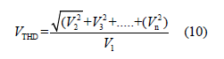
V1: is the RMS voltage of the fundamental frequency V2, V3, ….. Vn: are the RMS voltages of the harmonic frequencies
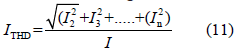
I1: is the RMS current of the fundamental frequency I2, I3, ….. In: are the RMS currents of the harmonic frequencies
The interpretation of the magnitude of its numerical result indicates that low values indicate a “cleaner” in voltage or current waveform with minimal distortion and high values reflects a significant amount of harmonic distortion, which can lead to equipment overheating, energy losses and other power quality issues.
Phasor technique
The phasor technique is a mathematical method that transforms time-varying sinusoidal quantities, like AC voltages and currents, into complex numbers called phasors, which represent the magnitude and phase angle of the sinusoid. This approach simplifies the analysis of circuits by allowing differential equations to be solved as algebraic equations, effectively treating reactive components (inductors and capacitors) like resistors with a complex impedance. It is particularly useful for finding the steady-state response of single-frequency systems and the vectorial addition of waveforms. A sinusoidal waveform, such as Acos(ωt + θ), is represented by a complex number (phasor) F with a magnitude A and an angle θ, denoted as F = A∠θ. This phasor is plotted on a complex plane, where the horizontal axis represents the real component and the vertical axis represents the imaginary component, with its length indicating the magnitude and the angle relative to the X-axis representing the phase.
Results
Data indicates the percentage of global greenhouse gas emissions attributed to transportation (around 28% in the U.S.) and building heating/cooling systems (around 15% globally), with overall global emissions per capita and total emissions being the relevant “rates” to track for climate impact (see Table 1). The growing dependence on renewable energy such as wind power and solar power has considerably burned the demand for AC drives. They help improve performance and help with power savings. According to the International Energy Agency, global renewable electricity generation is expected to reach over 17,000 TWh by 2030, marking a nearly 90% increase from 2023, driving the adoption of AC drives due to their efficiency and energy-saving benefits. International Market Analysis Research and Consulting (IMARC) Group provides an analysis of the key trends in each segment of the global AC drives market, along with forecasts at the global, regional, and country levels from 2025-2033. The market has been categorized based on power rating, voltage, application and end-use.
Table 1:Percentage of global greenhouse gas emissions1.

1 Ref. https://ourworldindata.org/grapher/co-emissionsby- sector
Table 2:Categories1 for quantitative assessment of global AC drives market.

1 Ref. https://www.imarcgroup.com/ac-drives-market
Table 1 & 2 together with renewable energy systems electrical drives which they are essential for use as speed control components for generators and motors, which is further creating positive opportunities for the market allow establishing a block diagram of a conceptual model that infers the contribution of this article should encapsulate the answers to the following questions: What are the types of energy consumed by society? What are the primary sources? What are the names of the resources that convert, transport, distribute and make primary energy consumable?
Conceptual model
By the block diagram in Figure 4 a conceptual model encapsulates: energy sources, major Energy Consumed forms and the connection between them (Figure 4). Heat, cool electricity and motion are forms of energy that are in societies demand, why:
Figure 4:Conceptual model encapsulating energy sources, kinds of loads and their connection.

Hot (Heat): for Thermal Comfort (Buildings and human bodies require heat to maintain comfortable temperatures, especially in cold weather, preventing illness and ensuring productivity) and for Industrial Processes. Many industrial and manufacturing processes require heat to function. Heat is the transfer of energy due to a temperature difference. Hot describes the state of a substance having a high temperature.
Cold: For Thermal Comfort (In warmer climates, cooling systems are essential to provide thermal comfort and prevent heatinduced mortality), for Preservation (Cold is crucial for refrigeration and cold storage to preserve food and other perishable goods). Cool energy means a transfer of energy concept. It is reverse to heat. The cooling mode is essentially the reverse of the heating mode; the device extracts heat from one area and moves it to another. For example, to cool a house, heat is absorbed from inside and expelled outside, while to heat the same house, heat is absorbed from the outside air and transferred inside. Cold describes the state of a substance having a low temperature.
Electricity: For Powering Technology (Electricity is the power source for most modern devices and systems, including computers, lighting and appliances), For industrial and Commercial Use (It fuels factories, offices and various other sectors of the economy), From Renewable Energy (integration of renewable energy sources into the grid also contributes to demand for electricity).
Motion: For Transportation (The demand for motion is inherently linked to vehicles and the movement of goods and people), For Machinery (Industrial machinery relies on motion to perform tasks and manufacture products, For Everyday Tasks (Many daily activities require motion, from operating household appliances to performing physical labor). Motive power is the energy or a device used to create motion and in the context of an electric drive, it refers to an electric motor that converts electrical energy into mechanical energy to power machines, vehicles or other equipment. A complete electric drive system includes the motor, a transmission to transfer the power and a control system to manage the operation of the motor.
There are two kinds of energy sources: FF (such as: Oil, Natural Gas and Coal) and RE such as solar, wind, geothermal, hydropower and Biofuels. FF produces greenhouse gas emissions (GHG). Sources and consumers must be connected.
Electricity energy system
Why is electricity energy-based society system instead based on heat, cool and motion? An electricity-based energy system is dominant because electricity can be efficiently transmitted, versatilely used for powering devices that generate motion, heat and cooling and is increasingly sourced from clean, renewable energy. While heat and motion are forms of energy, they are less efficient to transmit and less adaptable for the broad range of services required by modern society compared to electricity. The transition to electrical heating and cooling, particularly with heat pumps, further leverages this efficiency and supports grid decarbonization efforts.
In any type of system to provide a final consumer with energy, whether thermal (cold or heat), movement and electricity, it requires implementing a subsystem (see Figure 5) for its transfer, from the supplier to the aforementioned consumer. Advances in power electronics technologies for signal and data processing have enabled the implementation of solutions such as those illustrated in Figure 6 & 7. These advances are essentially revealed in the use of solid-state electronic converters for harnessing and transforming the types of energy available from renewable sources into electricity and for electric drives to convert the transferred electricity into motion. It is inferred that the thermal and movement energy transfer subsystem has been implemented by an electrical energy transfer subsystem. Advances in power electronics technologies for signal and data processing have enabled the implementation of solutions such as those illustrated in Figure 6 & 7. These advances are essentially revealed in the use of solid-state electronic converters for harnessing and transforming the types of energy available from renewable sources into electricity and for electric drives to convert the transferred electricity into motion. It is inferred that the thermal and movement energy transfer subsystem has been implemented by an electrical energy transfer subsystem.
Figure 5:For each type of energy consumed. For energy transfer from the supplier to the end consumer, its implementation is by transport and distribute networks.

Figure 6:Power electronics is the interface between electronics and power.

Figure 7:Power electronics is the interface between electronics and power.

Advantages of an electricity-based system: Versatility: Electricity is a universally applicable energy carrier that can be converted into almost any other form of energy-motion (motors), heat (heaters), light and computing power. Transmission: Electricity is the most practical form of energy for long-distance transport, allowing power generation to be located away from consumption centers. Renewable Integration: Renewable energy sources like solar and wind generate electricity directly, making a renewable energy system inherently electricity based. Decarbonization: Shifting from fossil fuel combustion to electricity-powered systems, like heat pumps, reduces emissions and improves air quality. Efficiency Gains: Heat pumps are highly efficient for heating and cooling, as they move heat rather than generate it, achieving efficiencies over 100% of the electricity consumed.
Limitations of heat and motion as primary energy systems: Inefficient Transmission: Heat is difficult to transport efficiently over long distances and its generation often involves inefficient combustion processes. Limited Versatility: Heat itself is used primarily for heating and some industrial processes, while motion is limited to mechanical applications like vehicles and machinery. Local Dependence: Many direct heat or motion-based systems require local fuel sources, which is less practical for large-scale, integrated systems.
Electrical power system: A simplified summary of its aspects and technologies
Indeed, there is a need to foster comprehensible knowledge about energy systems based on the use of electricity, accessible to the majority of the planet’s inhabitants. Therefore, time, effort and the sharing of experiences consolidated over many years of instruction allow us to understand Steve Jobs’s [23]: saying: “Simple can be more difficult than complex.” A simplified milestone on Electrical power system such as modeling aspects and technologies should include: (i) The evolution of power systems, from Traditional Power Systems to Modern Power System, is in full swing, (ii) Since the Second Industrial Revolution, the final stage of a power generation plant has been through electromechanical converters. These deliver to the centralized electrical power system a sinusoidal waveform of 60Hz in America and Japan and 50Hz in Europe. Typical technologies: centralized power systems without power electronics have as their essential elements rotating machines, transformers, switching devices and protection devices [24,25], (iii) A power electronic ac–ac converter [26], in generic form, accepts electric power from one system and converts it for delivery to another ac system with waveforms of different amplitude, frequency and phase.
As in the case of phase-controlled rectifiers, the important limitations of the phase-controlled ac voltage controllers are the poor power factor and the introduction of harmonics in the source currents (iv) Modern electrical systems are changing with a greater presence of DC networks, and these digital tools need to adapt to address the challenges of simulating hybrid AC-DC systems, (v) The program that for understanding in the Renewable Energy field was regards at the Faculty of electrical Engineering in Holon Institute of Technology [27,28], (vi) on Solar based technologies for building applications [24], (vii) The energy sector emitted a large fraction of 75 % of Global Greenhouse Gas (GHG) emissions in recent years. Oil, coal and natural gas provided 30%, 26% and 23% of the total energy supply respectively in 2020. This demonstrates a large dependency on fossil fuels for electricity generation [25] due to their high-capacity factors and (viii) [26] explores the challenges and advancements in the field of Electrical Engineering concerning the design and integration of renewable energy systems. The transition from traditional fossil fuels to renewable sources, such as solar, wind and hydroelectric power, requires a comprehensive understanding of the intricate engineering aspects involved.
The first step is to formalize how electrical voltage (or electric potential difference) is obtained. What waveforms have been selected, why, what they are used for, connection topologies with consumers and what laws allow for the analysis and design of electrical circuits and power systems. Electromotive Force (EMF) is not a force, but rather the energy per unit charge that a source provides to drive electric current through a circuit. Measured in Volts (V), EMF represents the potential difference established by a source, doing work on charges to move them from a lower to a higher potential, thereby creating a voltage that causes electrons to flow. EMF is often used interchangeably with voltage. EMF Works as: (i) a Potential Difference. This energy conversion creates a difference in electric potential between the two terminals of the source and (ii) a Driving Current. The potential difference or EMF, induces the flow of electric charges within a circuit, which results in an electric current.
Devices, sources and principles:
A. Batteries: Electrochemical cells convert chemical energy
into electrical energy.
B. Chemical reactions in batteries, which use electrochemical
processes to separate charges.
C. Electromechanical generators (EMG): driven by prime
movers (like the spinning of a turbine): Convert mechanical
energy, by electromagnetic induction into electrical energy.
Power converter: It is a device that changes electrical energy from one form to another, typically by altering the voltage, frequency or type of current (AC to DC or DC to AC). It is electronic systems that use components like diodes, capacitors and transformers to convert existing voltages or energy forms. Power electronic converters achieve this voltage transformation by rapidly switching electronic components, often involving coils (inductors; storing energy from the input during switching cycles by rapidly switching electronic components like MOSFETs (Metal-Oxide-Semiconductor Field- Effect Transistor) or IGBTs (Insulated Gate Bipolar Transistor) to control the flow of energy) which store and release energy, creating controlled voltage and current changes within the system. Keep in mind the following essential fact that switching technology IGBT is a hybrid design combining the high-input-impedance and fastswitching characteristics of MOSFET with the high-current and low-conduction-losses of a Bipolar Junction Transistor (BJT). The collapse or change in these magnetic fields then induces a voltage according to Faraday’s Law of Induction, allowing the converter to step up or step down the voltage, or convert between AC and DC power, depending on the circuit topology and switching patterns. Converters are designed to change voltage levels and forms (AC or DC) to meet specific power requirements, such as adapting household AC to the low-voltage DC needed by microchips or converting a battery’s high-voltage DC to a lower voltage for auxiliary systems in an electric car. They use solid-state electronics to control electrical power, enabling features like battery charging, motor control and grid integration for renewable energy. These converters are crucial for improving energy efficiency, managing power flow and ensuring the reliable and intelligent operation of modern electronic systems.
Transformer: device that transfers electric energy from one alternating-current circuit to one or more other circuits, either increasing (stepping up) or reducing (stepping down) the voltage. It is by using changing magnetic fields from another circuit. Transformers use two or more induction coils on a shared core to transfer electrical energy and change voltage, utilizing the timevarying magnetic field from a primary coil to induce voltage (EMF) in secondary coils. Transformers don’t generate electrical voltage; but it is a very important device. Electromechanical Generators (EMG), Transformer and Power converters work by changing magnetic flux, such as moving a conductor through a magnetic field, according to Faraday’s Law of Induction. Motion-induced and transformation-induced voltages both involve electromagnetic induction, where a change in a magnetic field creates a voltage in a conductor. In motion-induced voltage, a conductor moves through a static magnetic field, or a static conductor moves within a changing magnetic field. With transformation-induced voltage, a changing magnetic field, usually from an alternating current in one coil, causes a voltage to be induced in a nearby coil. Thus, Electromechanical generators are a motion-induced voltage. Transformer and Power converters are transformation-induced voltages.
Energy Density for electromechanical generators: A primary reason for using magnetic fields is their superior energy density. The energy stored in a magnetic field is proportional to the square of the magnetic flux density (B²), while the energy in an electric field is proportional to the square of the electric field intensity (E²). Because magnetic fields can store much more energy in the same space, they are more effective for energy transfer and generation. High Voltages are Impractical. AC power systems use sinusoidal waveforms because rotating generators naturally produce them by inducing voltage proportional to the sine of the angle of rotation. This sinusoidal shape is also beneficial because it can be easily stepped up and down in voltage using transformers, which helps in efficient power transmission. Furthermore, the predictable and smooth nature of sine waves results in less interference, lower power losses and less strain on electrical equipment compared to other waveforms. A pure sinusoidal waveform does not contain harmonics, which are unwanted frequencies that can cause distortions and other power quality problems.
AC, DC and three-phase systems are each superior for different applications, though three-phase AC is generally the best for highpower industrial (large machinery, industrial equipment, data centers and commercial buildings with high-power requirements) and grid applications due to its efficient, constant power delivery and ease of voltage transformation for long-distance transmission, it delivers more power more efficiently over long distances than single-phase, requires less conductor material (saving cost and space), and provides constant, smoother power for large machinery, especially three-phase motors, which are more efficient and have better torque characteristics than single-phase motors. Singlephase AC is best for most residential (Household Applications) and light commercial use, while DC is ideal for specific applications like large-scale energy storage, data centers and undersea transmission where its advantages of simple systems, efficiency in certain configurations, and fewer transmission lines offer benefits. For systems that require high-voltage DC, such as for long-distance transmission or interconnections between different AC grids, specialized High-Voltage DC (HVDC) systems are employed using power electronics to convert DC to AC or vice versa. In systems that generate DC, like solar energy, an inverter is used to convert DC power to AC power for use in the main grid or AC-powered appliances.
Power plants producing DC power: Solar Photovoltaic (PV) Plants: These use solar panels to directly convert sunlight into DC electricity. An inverter is then used to convert this DC power into AC power to send to the electricity grid.
Systems That Can Produce High-Voltage DC: High-Voltage Direct Current (HVDC) Systems use specialized electronic equipment to generate and transmit DC power at very high voltages. HVDC lines are used for very long-distance transmission with lower energy loss than AC lines and to connect separate AC power grids that might operate at different frequencies.
Power plants producing AC power
A. Thermal Power Plants: (using coal, natural gas, or other
fossil fuels).
B. Nuclear Power Plants.
C. Hydroelectric Power Plants: (water-powered turbines).
D. Wind Power Plants: (wind-powered turbines).
These plants use the principle of electromagnetic induction to convert kinetic or thermal energy into AC electricity. The AC output is then converted to higher voltages using transformers for efficient, long-distance transmission over power grids. An inverter is used to convert this DC power into AC power to send to the electricity grid. Direct current (DC) is a single, steady flow of electrons, while monophasic refers to a DC current that flows in only one direction, and three-phase is a system of three separate Alternating Currents (AC) staggered 120 degrees apart. Direct Current (DC) is a one-way flow of electrons, while single-phase and three-phase power refer to Alternating Current (AC) systems, which are characterized by their wave patterns and are used at different scales.
From the above it is established that AC, DC and three-phase systems, Figure 8, are of interest for the calculation of circuits (lumped parameter electrical systems) and electrical transmission and distribution networks (distributed parameter electrical systems). Lumped parameter electrical circuits assume signals transmit instantaneously and components are concentrated at single points. Distributed parameter electrical systems model parameters (like inductance or resistance) that vary over space, are essential for long or high-frequency systems like transmission lines where signal delay is significant. Under simplifying assumptions are considered time-invariant parametric coefficients, for example the resistance (in ohms) of the resistor, the inductance (in henries) of the inductor and the capacitance (in farads) of the capacitor. The waveforms supplied to the two types of electrical systems are of two types: constant overtime called direct current and sinusoidal both single-phase and three-phase [29-35].
Figure 8:Electrical voltage basic waveforms for powering: (a) DC, (b) AC and (c) three-phase systems.

From the theory of complex functions taught in Mathematics it is known that a complex and periodic function over time can be decomposed into a Fourier series. The main terms in a Fourier series are a constant term (DC term), representing the function’s average value and an infinite sum of sine and cosine terms, each multiplied by its corresponding Fourier coefficient (an, bn). These coefficients determine the amplitude of each sine and cosine component, allowing any periodic function to be decomposed into a linear combination of these simpler, oscillating waves (Figure 8). Harmonics occur in single-phase and three-phase steady-state circuits when a nonlinear load (like a rectifier, a transformer with a saturating core or certain types of power electronic devices) is connected to a sinusoidal power supply. These nonlinear loads partially convert the first harmonic (fundamental frequency) power from the source into higher harmonic frequencies, which then return towards the power source, distorting the voltage and current waveforms.
Keynote on steady and transient states in electrical circuits: This mathematical division in signals is established for the physical reason due to the presence of energy storage elements (inductors and capacitors) need time to adjust when a circuit’s conditions change, leading to a temporary, time-varying transient state before settling into a stable, unchanging steady state. The transient state occurs immediately after a disturbance, such as a switch being flipped or a voltage changing, while the steady state is the final condition where all the temporary effects of the disturbance have subsided (Figure 9).
Figure 9:Power triangle in sinusoidal AC circuits.

Figure 10 shows both FF and RE sources to generate three-phase electrical voltage. Electromechanical Generator (EMG) producing sinusoidal waveforms and by Power Electronic Converters (PEC) converting DC from PV to Three Phase Systems and Doubly-Fed Induction Generator (DFIG) whose stator is directly connected to the power grid, while its wound rotor is connected to the grid through a back-to-back power converter system which it enables to maintain a constant output frequency to the grid. In DFIG (Doubly-Fed Induction Generator) systems, harmonics are electrical distortions generated by the Back-to-Back (B2B) converter that injects a fraction of power from the rotor to the grid. These harmonics, particularly from the Grid-Side Converter (GSC) and Rotor-Side Converter (RSC), can cause grid instability and require specialized control methods for harmonic compensation and elimination. The back-to-back converter, essential for variable-speed operation and power control, utilizes PWM (Pulse Width Modulation) switching, which is a source of these harmonic currents.
Figure 10:Three systems are examples of three-phase electrical voltage.

Harmonics are present in PV systems due to the inherent nonlinear operation of inverters, which use high frequency switching techniques like Pulse Width Modulation (PWM) to convert DC power from solar panels to AC power. This rapid switching creates non-sinusoidal voltage and current waveforms, adding multiple frequencies (harmonics) to the fundamental 50/60Hz AC power. While inverters are designed to produce AC power, their non-linear nature means the output is not a pure sine wave, causing harmonics that can negatively impact grid performance and connected equipment. In AC electrical circuits with linear components such as resistors, inductors and capacitors, in the matter of power, there is the so-called apparent power (represented by a number in the field of Complexes) which is the composition of the active power (dissipated in the resistors) as well as the reactive power in the inductors and capacitors, in electrical circuits in which there is also the presence of non-linear loads, distortion power appears. In summary, it is as follows:
A. For simple, sinusoidal AC circuits, Apparent Power =
Active Power + Reactive Power (in a vector sense).
B. For complex, non-sinusoidal AC circuits with harmonics
[36-38] the total power is the sum of these three components:
Apparent Power = Active Power + Reactive Power + Distortion
Power (again, in a vector sense).
The effective voltage, also known as the Root Mean Square (RMS) voltage, is a measure of voltage in an Alternating Current (AC) circuit. It is the equivalent value of Direct Current (DC) voltage that would provide
The semiconductor switching itself is a non-linear process, meaning the current and voltage waveforms are not simple sine waves, but rather distorted waveforms containing the fundamental frequency plus multiples of it. Power electronic converters and Electromagnetic Compatibility (EMC) are intrinsically linked because converters, with their high-frequency switching, are a major source of Electromagnetic Interference (EMI) that can disrupt surrounding electronic equipment and themselves [39]. Electromagnetic Compatibility (EMC) is the ability of electronic equipment to operate correctly in its intended electromagnetic environment without causing or suffering from electromagnetic interference (EMI). Electromagnetic Interference (EMI) is the disturbance or unwanted disruption of electronic and electrical equipment, caused by external electromagnetic fields or noise. This interference can be a result of natural phenomena or man-made sources, impacting device performance through conduction (via wires or cables) or radiation (through air or space).
An Active Power Filter (APF), [40] is defined as an electronic device that enhances the quality of electrical energy. They remove current and voltage harmonics, by compensating for reactive power and addressing various unbalanced and flicker effects in electrical systems. APF is applied to a group of power-electronic circuits incorporating power switching devices and passive energystorage- circuit elements, such as inductors and capacitors. The functions of these circuits vary depending on the applications. They are generally used for controlling current harmonics in supply networks at the low- to medium-voltage distribution level or for reactive power and/or voltage control at high-voltage- distribution level. For suppressing Electromagnetic Interference (EMI) for reducing specific unwanted frequencies in power lines or offending frequencies, are inserted the EMI filters. They are electrical device. You can’t have AC power without any harmonics; instead, you use mitigation techniques to reduce harmonics, such as active filters that generate counter-harmonic currents, passive filters that use inductors and capacitors to create low-impedance paths, or Power
How do non-linear loads cause distortion?
Factor Correction (PFC) circuits that smooth the current waveform to a near-sine wave. Other methods include using phase-shifting transformers to cancel specific harmonics and ensuring loads are linear to prevent nonlinearities that generate harmonics.
Electromagnetic Interference filters [41] are electronic components that suppress Electromagnetic Interference (EMI) by attenuating unwanted high-frequency signals on power or signal lines, acting as a low-pass filter. They are crucial for improving device performance, reliability and safety by preventing noise from entering or escaping electronic equipment, thereby ensuring Electromagnetic Compatibility (EMC) and compliance with regulatory standards. Harmonic distortion in power systems is caused primarily by non-linear loads, which are devices that draw current in pulses rather than smooth, sinusoidal waves that don’t consume current in a smooth, sinusoidal pattern. Instead, they pull current in abrupt, non-sinusoidal pulses. Non-linear loads introduce additional frequencies (harmonics) into the electrical system. The fundamental cause of harmonics is the use of nonlinear loads, which are devices that don’t consume current in a smooth, sinusoidal pattern. Instead, they pull current in abrupt, non-sinusoidal pulses. These current harmonics, when flowing through system impedance, create voltage drops that distort the voltage waveform, leading to both current and voltage harmonic distortion in the system.
Examples of common non-linear loads
a) Power electronic devices: rectifiers, inverters and switchmode
power supplies (SMPS) introduce harmonics due to their
rapid switching operations, Electric vehicle chargers contribute
significantly to harmonic distortion in power systems.
b) Electronic equipment: Computers, LED lighting,
fluorescent lighting, printers, televisions and other office
equipment are common sources.
c) Industrial equipment: Used in industrial and HVAC
systems to control motor speeds, arc furnaces and welding
equipment and Variable Frequency Drives (VFDs) are significant
contributors.
Figure 11:Graphical basic understanding to distorted three- phase systems.

A. Current Harmonics: When a non-linear load is connected
to the power system, it draws a non-sinusoidal current, creating
harmonic current distortions in the circuit.
B. Voltage Harmonics: These distorted currents then flow
through the system’s impedance (resistance and inductance
of lines and transformers). In essence, the distortion of the
voltage waveform is a consequence of the harmonic currents
generated by non-linear loads and their interaction with the
system’s electrical impedance (See Figure 11).
C. Voltage Drop: The flow of harmonic currents through the
system impedance causes harmonic voltage drops. Magnetic
Saturation: When transformers and other inductive devices
become magnetically saturated, their magnetizing current
becomes non-linear, producing harmonic distortion.
D. Waveform Distortion: These voltage drops, in turn, distort
the smooth, sinusoidal shape of the supply voltage waveform,
creating voltage harmonics.
Harmonics’ consequences on power electric systems performance
a) Poor system design: Overloaded grids and a lack of proper
harmonic filtering strategies can lead to increased levels of
harmonic distortion.
b) Interactions with system impedance: Harmonics can also
interact with the power system’s impedance, which is especially
problematic when the grid is close to capacity, leading to severe
voltage distortion that can affect other facilities.
c) Harmonic resonance: In certain situations, system
components can resonate with harmonic frequencies,
amplifying them and leading to significant distortion.
d) Equipment overheating and failure: Harmonic currents
cause increased heating in transformers and other electrical
components, reducing their lifespan and potentially leading to
damage.
e) Reduced efficiency: The additional energy losses from
harmonic currents waste power, decreasing the overall
efficiency of the system.
f) System malfunction: Harmonic distortion can cause
sensitive electronic devices to malfunction, leading to errors or
unexpected shutdowns (Figure 11).
Theory and relationship
Efficiency & Power Transmission: Three-phase systems transmit three times the power as a single-phase system with only 1.5 times the conductors, making them more economical for longdistance bulk power transmission.
Tools
A. Phase Rotation Testers [42]: Used to ensure that the
phases are connected in the correct order for three-phase
motors, as incorrect order can lead to reverse operation.
B. Power Quality Analyzers [43]: Used to measure voltage,
current and other parameters in three-phase systems,
identifying issues like phase imbalances that can affect
efficiency.
C. Multimeters [44]: Capable of measuring AC and DC
voltages and currents, though specific settings are needed for
three-phase measurements.
Linear, non-linear loads in DC and AC (monophasic and three-phase) systems excited by sinusoidal voltage sources: how do voltage and current relationship?
Non-linear loads in DC and AC (monophasic and three-phase) systems draw distorted currents from sinusoidal voltage sources, creating harmonics that deviate from the ideal waveform. This relationship means that instead of a simple one-to-one voltage-tocurrent response, the load’s behavior changes with the signal level, causing energy to be converted into these higher harmonics, which are then returned to the power source. These harmonics cause various issues, including increased system losses, overheating, potential insulation breakdown and interference with sensitive equipment, significantly impacting power quality and system efficiency.
Impacts of non-linear loads
a) Increased Losses and Overheating: Higher harmonics lead
to increased current flow and consequently, greater losses and
overheating in conductors and equipment.
b) Resonance: The generated harmonics can resonate with
the system’s inductance and capacitance, leading to even
larger current or voltage distortions and potentially damaging
equipment.
c) Power Quality Issues: Harmonics degrade overall power
quality, affecting sensitive electronic equipment and the
accurate functioning of power meters.
Colophon
The authors suggest that you read the previous contribution [45] as a complement. This mini review is written in a very understandable and self-contained language for people with different academic training levels.
Discussion
This paper is the result of a great effort to make the difficult easy, to go from the phenomenological to the essential mathematical support and not the other way around. While it’s not possible to address every aspect in detail, it has been able to draw attention to the existence of all of them. It is therefore a starting point for motivating self-learning in society. The extensive bibliography is the authors’ legacy for self-learning.
Conclusion
The role of development in power electronics in moving toward modern electrical systems, harnessing renewable energy sources and replacing the long-distance transmission and distribution of thermal and motion energy demanded by industry and society this year, has been clearly demonstrated. This achieves the goal of contributing to essential energy knowledge in the sustainable energy transition. This contribution reveals that transforming society into an energy-sustainable society requires migrating from fossil fuels to renewables; However, this milestone introduces the decentralization of electricity generation. From the perspective of electrical engineering and technology, the structure of the electrical power system is migrating from a centralized form to a distributed and decentralized form, often referred to as the modern energy system. Readers are encouraged to address key aspects of both electrical engineering and power electronics technologies, automation, microcontrollers and digital signal processors and the instrumentation that today enables, among others, microgrids, smart grids, automatic synchronization and other features.
Conflict of Interest
The authors declare that they have no known competing financial interests or personal relationships that could have appeared to influence the work reported in this paper.
Authors

Luis Vazquez-Seisdedos Ph.D. degree in technical science (automation) His research interests included the control of electromechanical energy conversion systems, power plants based on both fossil fuel sources and Renewable Energy Resources (RES), Electric Vehicles (EV), energy storage subsystems and hybridization, electric drives, electrical traction systems and RES’s and EV’s integration into electrical power systems. He is currently in Electrotechnics Teaching Unit, School of Forestry Engineering and Natural Resources at Technical University of Madrid. ORCID: 0000-0001-5459-2265, SCIPROFILES Luis-Vazquez-Seisdedos, https://crimsonpublishers.com/cojec/editorial-board.php

Rahimil Vazquez-Gomez is a seasoned computer engineer with a passion for cloud computing and renewable energy from Florida international University (FIU). He is currently working as Principal IT Programmer Analyst for Florida Power and Light (FPL), located at Miami, Florida, US. His technical prowess extends to renewable energy where he has consistently delivered solutions that blend renewable energy with programming, offering significant opportunities for innovation, efficiency and sustainability.

Eberto Sedano-Herrera is a seasoned computer engineer. He worked with POTEVIO ATMs, China. Those ATMs are powered by photovoltaic systems with battery storage backup. Many alternative technical solutions contributed to the increase in their energy density, their relevance under use of aggressive environmental conditions such as areas of high salinity and relative humidity greater than 80%. He was recognized for the improvement of fault tolerance of a photovoltaic supply subsystem.
References
- Groumpos PP (2021) A critical historical and scientific overview of all industrial revolutions. IFAC-PapersOnLine 54(13): 464-471.
- Dincer I, Abu-Rayash A (2020) Energy sustainability.
- Components of energy system.
- Fell MJ (2017) Energy services: A conceptual review. Energy Research & Social Science 27: 129-140.
- Bakhsh S, Zhang W, Ali K, Oláh J (2024) Strategy towards sustainable energy transition: The effect of environmental governance, economic complexity and geopolitics. Energy Strategy Reviews 52: 101330.
- Conde JJ, Takano-Rojas H (2025) Rethinking energy transition: Approaches from social representations theory. Energy Research & Social Science 122: 104001.
- Chipangamate NS, Nwaila GT (2024) Assessment of challenges and strategies for driving energy transitions in emerging markets: A socio-technological systems perspective. Energy Geoscience 5(2): 100257.
- Torres-Rivera AD, Guevara-Valdez JA, Cruz-Morales V (2025) Energy transition and sustainability education: Bibliometric insights for holistic graduate program design. Energy Strategy Reviews 59: 101768.
- Energy transition: Balancing economic, political and social realities.
- Anthony EJ (2021) Advances in electrical engineering, electronics and energy: Global developments in new energy technologies and development of energy technology from the micro to the macro-scale. e-Prime - Advances in Electrical Engineering, Electronics and Energy 1: 100026.
- Kowalska-Pyzalska A (2024) Chapter 1. Introduction to Innovative Energy Services (IES) in transitioning energy markets. Energy Transition.
- Etukudoh EA, Fabuyide A, Ibekwe KI, Sonko S, Ilojianya VI (2024) Electrical engineering in renewable energy systems: A review of design and integration challenges. Engineering Science & Technology Journal 5(1):
- Rodriguez J, Blaabjerg F, Kazmierkowski MP (2023) Energy transition technology: The role of power electronics. Proceedings of the IEEE 111(4): 329-334.
- Marot A, Kelly A, Naglic M, Barbesant V, Cremer J, et al. (2022) Perspectives on future power system control centers for energy transition. Journal of Modern Power Systems and Clean Energy 10(2): 328-344.
- Zhang D, Rong C, Goh HH, Liu H, Li X, et al. (2023) Reform of electrical engineering undergraduate teaching and the curriculum system in the context of the energy internet. Sustainability 15(6): 5280.
- Saleh HM, Hassan AI (2024) The challenges of sustainable energy transition: A focus on renewable energy. Applied Chemical Engineering 7(2):
- https://www.dcec-engine.com/the-difference-between-linear-load-and-nonlinear-load/ojo
- https://www.riello-ups.co.uk/questions/39-what-s-the-difference-between-linear-and-non-linear-electrical-loads
- https://www.ytelect.com/blog/understanding-ac-electrical-loads-linear-vs-non-linear_b79 _
- https://www.sciencedirect.com/topics/engineering/voltage-total-harmonic-distortion
- https://nepsi.com/resources/calculators/total-harmonic-voltage-distortion.htm
- https://nepsi.com/resources/calculators/total-harmonic-current-distortion.htm
- https://www.jillhutchison.com/simple-can-be-harder-than-complex-steve-jobs/
- Esmaio MA, Rahmah MM (2025) The evolution of electrical grid systems from centralized to decentralized networks. 1(1): 14-24.
- Randolph J, Masters GM (2018) Centralized electric power systems. In: Energy for Sustainability. Island Press, Washington DC, USA.
- Biswas SP, Uddin MS, Islam MR, Mondal S, Nath JA (2022) Direct single-phase to three-phase AC/AC power converter. Electronics 11: 4213.
- Friman H (2017) New trends in the higher education: Renewable energy at the faculty of electrical engineering. Energy Procedia 115: 18-28.
- Friman H (2024) Shaping the engineers of tomorrow: Integrating renewable energies and advanced technologies in electrical and electronics engineering education. Energies 17: 4146.
- https://www.enerdynamics.com/Energy-Currents_Blog/Understanding-Single-phase-and-Three-phase-Electrical-Service-Configurations.aspx
- https://www.enerdynamics.com/Energy-Currents_Blog/Understanding-Single-phase-and-Three-phase-Electrical-Service-Configurations.aspx
- https://ccpia.org/commercial-electrical-systems-what-is-three-phase-power/
- https://www.hqonline.com/blog/dc-voltage-what-is-it-circuit-symbol-wire-color-codes
- https://iastate.pressbooks.pub/electriccircuits/chapter/alternating-current/
- https://www.raritan.com/landing/three-phase-power-explained
- https://www.shutterstock.com/es/search/3-phase-power-icon
- Willems JL (1992) A new interpretation of the Akagi-Nabae components for nonsinusoidal three-phase situations power. IEEE Transactions on Instrumentation and Measurement 41(4): 523-527.
- Hirofumi A, Satoshi O, Hyosung K (1999) The theory of instantaneous power in three-phase four-wire systems: A comprehensive approach. Conference Record of the 1999 IEEE Industry Applications Conference. Thirty-Fourth IAS Annual Meeting 1: 431-439.
- Salmerón P, Herrera RS (2009) Instantaneous reactive power theory-a general approach to poly-phase systems. Electric Power Systems Research 79(9): 1263-1270.
- Ramya K, Gopalakrishnan J, Chokkalingam B, Verma R, Mihet-Popa L (2025) A comprehensive evaluation and assessment practices of electromagnetic interferences in electric vehicle. In IEEE Access 13: 40520-40560.
- Dash DK, Sadhu PK (2023) A review on the use of active power filter for grid-connected renewable energy conversion systems. Processes 11: 1467.
- Tan R, Ye S, Peng Q, Du C, Zhou Z (2025) Research on efficient prediction and suppression of electromagnetic interference in electric drive systems. World Electr Veh J 16: 201.
- https://www.testinstrumentsolutions.co.uk/knowledgebase-article/how-to-measure-phase-rotation-with-a-multifunction-tester
- https://www.elspec-ltd.com/what-is-a-power-quality-analyzer/
- https://tense.com.tr/en/what-is-a-multimeter/
- Vazquez-Seisdedos L, Vazquez-Gomez R, Sedano-Herrera E (2025) The need for energy transition to build sustainable societies. COJ Elec Communicat 3(3): 1-4.
© 2025 Luis Vazquez-Seisdedos. This is an open access article distributed under the terms of the Creative Commons Attribution License , which permits unrestricted use, distribution, and build upon your work non-commercially.
Editor In Chief


.jpg)


Signup for Newsletter

Quick Links
 Editorial Board Registrations
 Submit your Article
 Refer a Friend
 Advertise With Us
Our Recent Edition

.jpg)


Top Editors


.jpg)


.bmp)
.jpg)
.png)
.jpg)


.jpg)


.png)

.png)


.png)


Financial Support

Sponsors

Latest e-Books

Latest Video

 a Creative Commons Attribution 4.0 International License. Based on a work at www.crimsonpublishers.com.
Best viewed in
a Creative Commons Attribution 4.0 International License. Based on a work at www.crimsonpublishers.com.
Best viewed in