
- About Us
- Information
-

The Author ensures that the research has been conducted responsibly and ethically with adherence to all relevant regulations. read more..
- For Authors
- For Reviewer
- Manuscript Guidelines
- Membership
- Publication Ethics
-
- Journals
- Reprints
- e-Books
- Videos
- Policies
- Contact Us
 COVID-19
- Submissions


Full Text
COJ Electronics & Communications
The Machine that Lives Forever-Blubot
Michael Walton* and John Woods
School of Computer science and Electronic Engineering, University of Essex, UK
*Corresponding author: Michael Walton, School of Computer science and Electronic Engineering, University of Essex, Colchester, UK
Submission: November 27, 2019;Published: February 10, 2020

ISSN 2640-9739Volume1 Issue5
Abstract
The Machine That Lives Forever is a concept which describes an electronic object that harvests and manages its energy; drawing parallels with various human and animal models. A basic life cycle is realised that follows the rest-feed-work process ingrained into every living creature. The challenge is to find and store energy; when enough energy has been accumulated a work ‘task’ is executed, when the energy store is then depleted hibernation occurs in a low power state allowing for energy recharge. This cycle is then repeated forever. This paper aims to design, produce and characterise a low-power Bluetooth enabled self-sufficient smart robot. Designed to be a digital hybrid utilising a microprocessor, it provides energy harvesting facilities along with various sensors to enable interaction with its surrounding environment.
Keywords: Energy harvesting; GA; Wireless power; Survival; Rectanna; Meshing
Introduction
A Bluetooth low energy programmable platform that implements the following basic functionality [1]:
1. Have a method to receive energy in some form
2. Harvest and store this energy
3. Monitor the level of the stored energy
4. Have a hibernation mode where its energy usage is reduced to a minimum
5. Execute a task, where it consumes the stored energy
6. Maximize its ability to have energy delivered efficiently
7. Be able to repeat its sleep-work-sleep cycle indefinitely
8. Be able to communicate with other machines
9. Be able to report its current status
10. Allow remote control and commands to be received
11. Provide the ability to update its internal systems while in the field
The platform is motor driven; it contains various on-board short range and long-range
communication facilities along with sensors to detect surrounding objects.
The energy delivery is in the form of solar energy. The energy storage is in the form
of capacitors (super caps). The solar panel charges up the capacitors providing an energy
store available for later use. Highly efficient energy harvesting has been implemented which
maximize the absorption of very low amounts of available energy. The bot monitors the level
of energy stored within the capacitors; when the level passes an upper HIGH threshold value,
the bot wakes up and perform its task. As the bot uses the energy the level in the capacitors
drop, when the level drops below a LOW threshold, the bot ceases performing task execution
and returns to a minimum energy consumption mode, allowing the energy store to be again
recharged from the solar panel.
The ‘task’ is to harvest energy for survival; it is able to track the direction of the brightest
light. This is achieved using two photodiodes positioned either side of the bot. The photodiodes
react to the light and allow current to pass dependent on the level of light, the magnitude of
this input is used to adjust the bot’s direction of travel. Two motors are installed on each side of the bot to provide movement; the motors speed is manipulated
to control its direction of travel. Ultrasonic radars located on the
front and rear of the bot provide ‘eyes’, these surface the ability to
discover objects and their distances.
The bot uses both a LOW and HIGH threshold to monitor its
energy storage levels; this provides a hysteresis which prevents
the bot from entering an infinite cycle of its wake-up energy
requirements immediately depleting its accumulated energy
storage rendering them needing again to recharge. Infrared
transmission and reception, allowing localized talking and hearing,
coupled with near-field-communications (NFC) is implemented
to facilitate short distance intercommunication between bots.
Bluetooth LE (Low Energy) communications [2] is used for longdistance
control and monitoring.
EEPROM facilities are available so command lists and current
states are stored and retrieved in the event of total energy loss,
providing an ability to remember. A computer interface has been
designed to allow monitoring and control of the bots.
The performance and testing parameters of the bot consists of the following:
1. Sleep voltage threshold
2. Wakeup voltage threshold
3. Current consumption while sleeping
4. Current consumption while executing its task
5. Recharge time from Low to HIGH threshold under controlled
light
6. Task execution time before Low threshold is reached
7. Ability to maximise energy delivery
8. Size and weight of the bot
Outline of Objectives
The entire design [1] is based around a Nrf52832 [3], a powerful, highly flexible ultra-low power multiprotocol SoC. With an internal clock speed of 64MHz, 512Kb of flash and 64Kb of ram it is more than adequate to interface all the peripherals. Current consumption of 58uA/MHz is possible, with sleep currents as low as 1.9uA. The device is configured in a low current DC-DC mode where it uses an external inductor and capacitor to enable its internal boost circuitry. The primary oscillator is a 32MHz crystal, and the lowfrequency clock is enabled using its internal resonator. Operational input voltage is from 1.7V to 3.3V. As for hardware peripherals, the Blubot makes use of 3 PWM ports, an I2C port, a UART, NFC port, 2.4GHz radio output, SAADC port and debug interface. An nR52-DK [4] evaluation board was acquired to ensure the microcontroller was fit for purpose; it allowed the Bluetooth and peripherals to be tested individually along with providing a working reference design. Where possible, elements of the circuits were simulated using National Instruments MultiSim [5] and TINA-TI [6].
Power
Power comes from the sun via a solar panel connected to a
BQ25570 [7] Nano Power Boost Charger and Buck Converter. This
is a highly efficient energy harvesting controller which is capable
of capturing very small microwatts of energy and storing it in an
energy store. The BQ25570 [7] offers automated threshold-based
monitoring of the energy levels and provides an output which is
used to power the microcontroller via a MOSFET transistor when
sufficient energy has been collected. The energy store consists
of a bank of super capacitors rated up to 5 volts. The BQ25570 is
configured to prevent the charge voltage from rising above 3.3V;
this allows the microcontroller to operate directly from the energy
store without further regulation.
The capacitors charge time is calculated and graphed using the
following formula:
τ = RC
Vout =VS(1−e−t/τ )
Two capacitors, C1 and C2, of 3.3F are in series, so:
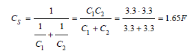
Assume an R value in this instance of 100Ω, and VS is 4V
τ = 100 ⋅ 1.65 = 165
The BQ25570 [6] also has an internal boost converter which is
used to provide a stable 5V output rail when enabled; this is used
to power the ultrasonic radars and provide a ‘high-speed’ option
for the motor drive. A bq25570EVM-206 [7] evaluation board was
purchased to fully understand how to setup and implement the part.
Overcharge protection, MPPT (Maximum Power Point Tracking),
Under-volt protection, Voltage OK and boost voltage output are all
set using a collection of high resistance divider networks.
A power level monitor input is fed into the microcontroller using
its SAADC port configured with an internal voltage reference of
0.6V enabled. The voltage level is first passed through three diodes
dropping it by ≈1.5V before then being passed through the SAADC
gain blocks to reduce it further by¼. The microcontroller is able
to monitor and detect the energy level and prepare for hibernation
when the level reaches ≈1.8V. At 1.7V the BQ25570 [6] kills the
power to the microcontroller and concentrates on harvesting more
energy. The ideal goal is for the microcontroller to stay powered in
a low current hibernation state allowing the BQ25570 [6] to raise
the energy store level without the need for switching off the supply.
Bluetooth
Bluetooth 5 Low Energy [2] connectivity is provided by the Nrf52832 [3], a 2.4GHz RF output is available which is connected to a PCB microstrip antenna. Transmission up to +4dBm of power is possible with data rates up to 2Mbps. The microstrip antenna is fine-tuned to 50Ω using an impedance matching network configured in a PI arrangement. A coaxial connector with built-in switch has also been provided; this allows an external antenna to be connected offering higher gains. Bluetooth is configured to operate using a peripheral personality, and it periodically advertises its presence as long as the energy stores allow, and it has not entered into a hibernation state. A custom service and characteristic are implemented using its own vender specific UUID allowing up to three concurrent connections.
Motors
Two motors are controlled via PWM using a DRV8836 [8] duel DC motor driver. Offering a 95nA sleep current and operation from 2V, it provides two H-bridge type outputs possible of delivering 1.5A each. This part takes two PWM inputs where the duty cycle is used to determine the speed of the motors; it also provides two inputs which are used to change the direction of travel. The supply voltage to the IC is selected to be either VDD or 5V via an ADG849 [9] CMOS single pole double throw switch. The 5V comes from the BQ25570’s [8] boost converter and is used to obtain a higher and more consistent drive speed at the cost of larger current consumption. When not being used, the DRV8836 is placed into a sleep mode, where its current consumption is reduced to a maximum of 95nA. The motors are rated from 3V to 7V but still work down below 2V. They are geared using an 85:1 ratio. A DRV8836EVM [10] evaluation board was obtained to test the viability of the motor control subsystem along with the early discovery of current consumption.
Ultrasonic radars
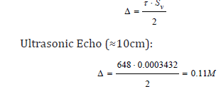
The ultrasonic rangefinders are based on a 40kHz ultrasonic transmitter and receiver. A short ultrasonic burst is transmitted from the transmitter modulated using a PWM channel. When there is an object in the path of the ultrasonic pulse, some portion of the transmitted ultrasonic wave is reflected, and the ultrasonic receiver detects an echo. Measuring the elapsed time between the transmission and the receiving of the echo along with the knowledge of the speed of sound in the medium, the distance between the receiver and the object is then calculated using the formula:
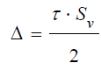
Where Δ =Distance in M, τ = Time of echo peak in μs and Sv =speed of sound (0.0003432M/μs @ 20 °C).
A full H-bridge is used to generate the pulses from the transmitter; this allows maximum power output for given supply voltage. The received signal is usually very weak (less than 1mV), a high gain low noise amplifier is used to recover the signal and prepare it for sampling. The amplifier is configured in a twostage inverted band-pass setup. Each stage has a gain of around 67 (36.5dB), and the circuit has a combined voltage gain of 73dB. A single power supply voltage is used, and the output voltage of the op-amp is centred at VDD/2 (2.5V). A signal diode, capacitor and resistor are used to demodulate the signal, and a coupling capacitor is used to remove the DC component. Due to the current consumption needed to operate a single rangefinder, an ADG849 [9] CMOS single pole double throw switch is used to select which module to power and sample. The voltage source is the 5V which comes from the BQ25570’s [7] boost convertor.
Light detection
Two photodiodes are connected to the microcontrollers SAADC engine, the positive reference of the ADC is internally set to VDD/4 and the signal is passed via an internal gain block set to 1/6, this enables the photodiodes to always provide an unsaturated input value regardless of the current level of VDD. Before a reading is taken, the appropriate output of the microcontroller must be set HIGH, this provides a VDD source to the photodiodes and they begin to conduct. The reason for this configuration is to prevent the series resister from constantly consuming current from any leakage which maybe flowing through the photodiode. The ADC results of the two inputs are compared to each other, allowing discovery of brightest light position. These results are fed into the PWM engine to allow a direction change to benefit.
Infrared communications
An Infrared LED optimised for 38kHz modulation is used for IR transmission, this is implemented in firmware using a 9600 baud bit-bang technique that toggles the PWM output connected to the LED. Reception is dealt with by using a TSOP38238SS1V [11] IR Receiver Module which is capable of an operational voltage from 1.7 to 5.5V while consuming a very low current of 350nA. Modulated IR reception is automatically demodulated by this part, and a digital output is provided to enable easy interfacing with the microcontroller. The V letter of the part number denotes that it is a special low voltage variant of the device capable of operation down to 1.7V.
NFC
Near Field Communication has been implemented using a differential copper loop antenna printed on a flex PCB material. It is connected via an L configured impedance matching network using an FCC type connecter. The loop is tuned to resonate at 13.56MHz and is compatible with Type 2 NFC-A tags [12]. It allows an RF carrier to receive the modules data using a back-scattering technique.
EEPROM
A broad voltage range I2C EEPROM part 24AA1025 [13] has been implemented to provide non-volatile storage. This is controlled via the microcontrollers I2C peripheral, it offers 1024Kb (128K x 8) of storage with a low 450uA read current. The power for the EEPROM and the supply for the two mandatory I2C pullup resisters are provided via a microcontroller pin; this ensures zero current consumption when the part is not being used.
Firmware and software
Firmware has been written using the GNU Arm Embedded Toolchain [14], GNU Make [15] and the Eclipse IDE [16]. All firmware was written using C and made good use of the SDK provided with the nRF52832 [3]. The SDK covered the low-level communications setup for the Bluetooth and provided certification in the form of a pre-certified Bluetooth SoftDevice. A custom library was written which exposes interfaces to all the external peripherals implemented on the board. The DFU bootloader was written using Keils uVision IDE [17].
A GUI front end has been created which allows real-time control of the bots functions. Written using C++ with Embacadero’s RAD Studio [18] IDE, it runs on multiple operating systems and devices. Support includes Windows 32/64bit, Android mobile devices and pads, iPhones, iPads and Mac OS. The interface uses the user devices’ built-in Bluetooth hardware to establish a connection to the bot. It provides a means to scan for all bots within range and allows the user to select the one they wish to interact with. When connected all of the bots become accessible and are manipulated via on-screen controls. A status update is continually sent from the bot which shows its energy store level and last sensor readings.
Programming
An SWD JTAG interface is available for programming the nRF52832 [3]. A SEGGER JLink [19] debug probe is used to provide microcontroller flash and debugging facilities. For the release of the bot, JLink is used to flash the bootloader and softdevice, both of which are firmware components that are unchanged as the bots main firmware is developed and extended. The bootloader is then used to program the main firmware ‘over the air’. Any future changes to the main firmware are re-programmed using the same ‘over the air’ method removing the need for the JLink device.
PCB
Altium Designer 18 [20] was used to capture the circuit schematic and design the PCBs for both Blubot and the rangefinders. The PCB is a four Layer FR4 technology which uses one mid layer to assist routing and a second mid layer to provide a power plane. Ground pours are present on top, bottom and mid layers with copious amounts of via stitching throughout and around the edge, all aiding in reducing high-frequency resonances between layers in the PCB escaping (causing EMI) and lowering overall ground impedance. The Bluetooth microchip antenna is fed using a 50Ω impedance-controlled trace with stitched shielding either side.
Discussion
Current consumption while executing its task has been recorded without motor movement. Task execution time before low threshold is taken with motor drive enabled at full speed and measures the time the bot moves from its highest energy store level of 3.3V to its lowest of 1.8V.
Power
Quite impressive current restraints have been achieved with the design. Three basic modes of operation have been implemented:
1. Deep Hibernation
2. Advertising
3. Connected
During Deep Hibernation, a minimum current draw is realised, all communications and radio are disabled and as many internal peripherals as possible are disabled. To wake from this state, the on-board PCB button must be pressed causing an interrupt to occur within the microcontroller. Current consumption during Deep Hibernation is sub 500nA with a recorded minimum of 82nA, averaging at 203nA. When woken, the mode transitions to Advertising. This mode enables Bluetooth discovery. The radio is enabled, and short advertisement bursts are transmitted every 3 seconds. During this mode, the Bot is effectively waiting for a controller to make contact and form a connection with it, if this does not happen within one minute, the mode reverts to Deep Hibernation. Current consumption during Advertising contains peaks where the radio is active and transmitting; this is controlled by manipulating the advertisement interval if desired. A peak averaging 1.85mA is recorded during the transmission. The connected mode is active when a controlling device has initiated and established a full Bluetooth connection, this mode is active until the connection is dropped, after which it reverts to Advertising. During a Connected state, the average is recorded at a consistent 1.74mA.
The BQ25570 [7] performs extremely well, under test it
provided an energy store charge under ambient light which was
beyond expectations. It was able to successfully harvest tiny
amounts of energy and incrementally add it to the super caps. It
also provided a stable 5V output even when energy store levels
were below 1.9V. Charging of the energy store stopped at 3.28V
to prevent overcharge and over-voltage conditions (set by the
BQ25570’s [7] resisters) and the Output OK signal was detected
when the store level hit 2V, disabling itself when it drained to under
1.8V. The power ADC sample process takes ≈25uS. After the load
resister is switched in an 8uS delay is applied before ADC sampling
is initiated, this prevents the initial peak from interfering with
the sampled result. The input impedance is 100K so based on the
microcontroller spec ≈15uS of acquisition time has been configured.
Ohms law states the current flow at 2.7V through the 100K
resister would be 𝑉𝑅 = 2.7100000 = 27uA, this is only consumed when the microcontroller enables the sample pin.
Bluetooth
The microstrip antenna was tested using a VNA, the VWSR showed that reflection is minimised at a frequency centred around 2.422GHz, meaning that better, more efficient power transfer is possible at this frequency. Wikipedia states “Bluetooth operates at frequencies between 2402 and 2480MHz, or 2400 and 2483.5MHz including guard bands 2MHz wide at the bottom end and 3.5MHz wide at the top” [21]. The Smith Chart view proved that a good 53.5Ω impedance match at 2.422GHz was achieved. This result is of course highly dependent on PCB materials, enclosure and placement of nearby metallic bodies, the tuning process should be re-visited if major changes or board revisions take place.
Motors
The motors; using a gear ratio of 85:1; proved to have a great balance of torque versus current consumption. The energy store is more than adequate to provide their initial start-up in-rush needs. Bot movement was effortless and speeds appropriate. Under test at near full speed, the two motors running together could consume more than 50mA; however, with some intelligent management of the drive speeds and using the ‘pulsed’ run mode made available via the firmware, the current consumption is managed efficiently. Full direction control allows the ability to turn at any angle in both forwards and reverse. Enabling and switching in the 5V supply from the BQ25570 [7] provides a high-speed option at the cost of extra current-this should be used wisely under low light conditions as it quickly depletes the energy store.
UltraSonic radar
It was found via experimentation that at least four pulses were needed to provide a quality stable echo. Less than this reduced the overall transmission power; more than four seems to have little positive effect. Ultrasonic echo testing was done by holding a plastic sheet in front of the transducers at fixed distances and capturing the echo on an oscilloscope. The formula below is used to confirm the results further.
Current consumption is further reduced by changing the H Bridge setup, exchanging the transistors for MOSFETs offers more efficiency. The voltage divider circuitry providing the biasing for the receiver op-amp could also have its values tweaked to reduce its consumption.
Light detection
Photodiode operation uses a 1M resistor to reduce current consumption when enabled, this also has an effect of presenting very high impedance at the ADC module, as such, at least 40uS of acquisition time is needed to allow the ADCs internal sampling capacitor to charge adequately. Ohms law states the current flow at 2.7V through the 1M resistor would be 𝑉𝑅 = 2.71000000 = 2.7uA. This is only consumed when the microcontroller sets the pin HIGH for a sample.
Infrared communications
A 38kHz modulated square pulse signal was used to drive the IR LED, this is generated using the PWM engine and has bit timing related to a set UART baud rate. Currently, the setup sends bytes of data at 9600 baud. The IR detector receives a 38kHz modulated signal and de-modulates it. This signal is fed into the microcontroller’s hardware UART peripheral for byte decoding at the correct baud rate. The current firmware implementation allows single byte transmission via IR and has a 32byte FIFO buffer for reception which allows one byte at a time to be read by the GUI.
NFC
The NFC flex antenna was tuned using the L matching network component spaces reserved by the schematic. The result was tested and tweaked using a magnetic tracking antenna developed by Aaronia AG [22]. This highly directional active antenna was specially designed for signal tracking and field strength measurements. Distance performance was achieved ranging up to four inches using an active tag reader; the position of the antenna greatly influences its performance.
EEPROM
EEPROM write sequences take ≈600uS and read ≈400uS. The write command also needs an additional 4.3mS to allow the operation to complete internally, this is a mandatory delay, and the IC must be powered for this entire period if a write is desired. A write operation is also expensive regarding current, which exhibits peaks of up to 5mA, compared to a read which is completed in under 450uA. The firmware currently allows single byte read and writes from any specified EEPROM address.
Firmware and software
A firmware library has been written which allows basic manipulation of all implemented peripherals using Eclipse [16]. The library is easy to understand and use and well abstracted away from normal firmware development, all peripherals are accessed using high-level function calls without the need to understand the detail of implementation. All functions of the library have been implemented with access via the GUI interface for demonstration and testing purposes. Firmware’s can be developed using these libraries which provide intelligent operation and utilisation of the Bots, aiding research and teachings. The developed firmware’s are programmed and tested using the Bluetooth Over-The-Air update facility. Over-The-Air firmware updating is fully functional using the nRF Connect software supplied by Nordic Semiconductor [3]. It allows quick and efficient in-field firmware updating with the ability to recover from failed attempts if the Bot suffered a power loss during the transfer. The library ensures that all power needs of the peripherals have been minimised, and when used the operations incur minimal current consumption for the shortest possible time to obtain results. The Eclipse IDE [16] proved to be a good choice for firmware development, although the initial setup to enable the Nordic [3] SDK to be imported and compiled was rather involved, the result was both easy to use and debug. The SEGGER [19] J-Link integrated seamlessly, and none of the required tools had any limitations or license expenses.
The GUI software worked out very well, with both a windows version and android version deployed for test it allowed easy control of the Bots function. Discovery of all Bots in range is possible allowing the user to select the Bot they wish to manipulate. Service and character discovery, auto selection and connection are all implemented behind the scenes to provide the user with an easy to use and understand interface. A windows and Android deployment were tested, and both provided full control of the Bot, iPhone and Mac versions have been compiled however deployment hardware was not available for final tests.
PCB
The BluBot PCB contained many small SMT components, in particular, the nRF52832 microcontroller with 48 pins in a fine pitch QFN package was very difficult to solder. The board has four layers, three of which contain a ground polygon pour with lots of via stitching, the QFN48 package also has an exposed ground pad with vias embedded to maintain its thermal performance; this all meant that providing adequate heat to allow solder reflow was quite a challenge. Particular design attention was needed for the BQ25570 [7] due to its handling of very low microwatt input energy. Large low impeding PCB traces were required with ground guarding and multiple ground planes to reduce leakage and loss to an absolute minimum. For the next PCB revision; various board shape tweaks have been implemented, more room for the motor fixings has been provided as well as removing the need to have the PCBs individually routed; this results in ‘V’ scoring becoming a viable manufacture option resulting in reduced board costs [23].
Conclusion
Regarding current consumption the BluBot surpassed all
expectations; even during full Bluetooth connection, current draw
was manageable. In deep hibernation mode, the super caps stay
charged for many days indicating leakage is very low indeed. Even
under low ambient light conditions BluBot still managed to provide
levels of charge to its energy bank and hold its own, low ambient
light alone was enough to counteract the remaining leakage in
the design. Software control, Bluetooth signal and peripherals
all proved to be reliable and usable; the drive systems enabling
movement are both responsive and effective.
There are still opportunities in this design to find and reduce
leakage current further. Using a low-frequency crystal for the
secondary oscillator in place of the internal RC consumes less
current. A bigger more efficient solar panel deployed by designing
a plastic frame to support it from the circuit board; the extra energy
intake would allow prolonged operation during very low ambient
light conditions. More current characterisation and profiling is
needed to fully understand all aspects of the design and make
improvements. Various other energy sources can be profiled
using this design, Peltier sources, thermo-energy devices and
RF scavenging all provide a means to feed energy requirements.
Ultimately a small army of BluBots ought to be built to explore
further intelligent interaction and decision making between the individual units themselves. The software and firmware have both
been designed to support this and to further promote this idea the
PCB has been revised to reduce manufacture and build costs.
BluBot offers a solid ‘body’ design which is used to develop
and explore the parallels between machines and living beings.
It provides an efficient energy-using engine with a beating heart
which needs both rest and food to be able to properly function. It
surfaces sensors which allow it to see, hear, talk, remember, learn
and move. Personality based evolution has been implemented
to allow self-learning and survival [24]. The final goal being the
realisation of a useful self-sustaining Bot that really can survive and
live forever.
References
- Walton M and Woods J (2018) Blubot (Schematics). School of Computer Science and Electronic Engineering, University of Essex, Colchester, England.
- Bluetooth SIG Inc. (2018) Radio versions | bluetooth technology website. Bluetooth SIG Inc, Lake Washington, Kirkland, USA.
- Nordic Semiconductor (2018) nRF52832 / Bluetooth low energy / Products / Home - Ultra Low Power Wireless Solutions from NORDIC SEMICONDUCTOR. Nordic Semiconductor.
- Nordic Semiconductor (2018) nRF52 DK - Development kit for nRF52832. Nordic Semiconductor.
- National Instruments (2018) NI Multisim: Powerful circuit design and teaching software, National Instruments.
- Texas Instruments (2017) SPICE-Based analog simulation program. Texas Instruments Incorporated.
- Texas Instruments (2018) BQ25570 ultra low power harvester power management IC with boost charger, and nanopower buck converter.
- Texas Instruments (2017) Ultra low power management IC, boost charger nanopowered buck converter evaluation module. Texas Instruments Incorporated.
- Texas Instruments (2017) DRV8836 1.5A low voltage stepper or single/dual brushed DC motor driver. Texas Instruments Incorporated.
- Analog Devices (2018) ADG849 3V/5V CMOS 0.5Ω SPDT switch in SC70. Analog Devices Inc.
- Texas Instruments (2017) DRV8836 evaluation module. Texas Instruments Incorporated.
- Vishay (2018) TSOP382.., TSOP384.. product information. VISHAY.
- NFC Forum (2018) Tag type technical specifications, The Near Field Communication (NFC) Forum.
- M Technology (2018) 24AA1025 - Memory microchip technology Inc.
- Arm Limited (2018) GNU arm embedded toolchain. Arm Limited (or its affiliates).
- GCC Team (2018) GCC, The GNU compiler collection. Free Software Foundation, Inc.
- Eclipse Foundation Inc (2018) Eclipse desktop & web IDEs. Eclipse Foundation, Inc.
- Keil ARM (2018) uVision IDE. Arm Limited (or its affiliates).
- Embarcadero (2018) RAD studio software overview. Embarcadero Technologies, Inc.
- SEGGER Microcontroller (2018) J-Link Debug probes | SEGGER - The embedded experts. SEGGER Microcontroller GmbH.
- Altium LLC (2018) PCB Design Software | Innovation for PCB Design | Altium. Altium LLC.
- Wikipedia (2018) Bluetooth, implementation. Wikipedia.
- Aaronia AG (2018) Active magnetic loop antenna MDF 960X. Gewerbegebiet Aaronia AG.
- Walton M, Woods J (2018) The machine that lives forever – Machines with attitude. (Under Review), School of Computer Science and Electronic Engineering, University of Essex, Colchester, 2018.
© 2020 Michael Walton. This is an open access article distributed under the terms of the Creative Commons Attribution License , which permits unrestricted use, distribution, and build upon your work non-commercially.
Editor In Chief


.jpg)


Signup for Newsletter

Quick Links
 Editorial Board Registrations
 Submit your Article
 Refer a Friend
 Advertise With Us
Our Recent Edition

.jpg)


Top Editors


.jpg)


.bmp)
.jpg)
.png)
.jpg)


.jpg)


.png)

.png)


.png)


Financial Support

Sponsors

Latest e-Books

Latest Video

 a Creative Commons Attribution 4.0 International License. Based on a work at www.crimsonpublishers.com.
Best viewed in
a Creative Commons Attribution 4.0 International License. Based on a work at www.crimsonpublishers.com.
Best viewed in