- Submissions

Full Text
COJ Electronics & Communications
Design of a 0.22THz, 100W Planar TWT for Ultra Wide Band Wireless Communication
Vishnu Srivastava*
Microwave Tubes Division, CSIR-Central Electronics Engineering Research Institute, India
*Corresponding author: Vishnu Srivastava, Microwave Tubes Division, CSIR-Central Electronics Engineering Research Institute, Pilani-333031, Rajasthan, India
Submission: May 23, 2018;Published: July 12, 2018

ISSN 2640-9739 Volume1 Issue1
Abstract
Development activities addressed to 0.22THz centre frequency is of significant importance for ultra wideband communication and remote sensing because of the available atmospheric spectral window over a band from 0.20THz to 0.30THz. 0.22THz planar TWT of output power more than 100W, gain more than 30dB, and bandwidth more than 30GHz is designed for high data rate wireless communication, imaging and remote sensing. Planar TWT is designed using a rectangular sheet electron beam of beam voltage 20kV and beam current 100mA, and of beam size 100m (thickness) x 600m (width). A planar staggered double vane loaded rectangular waveguide slow-wave structure (SDV-SWS) of broad bandwidth, high impedance and low circuit loss is designed for the 0.22THz TWT. Planar structure is used because it is compatible for sheet beam operation and it is also easy to fabricate using MEMS technologies. Large signal analysis code SUNRAY-P, developed to determine RF performance of a planar TWT with sheet beam, is used to design the 0.22THz 100W TWT with sever, couplers and phase velocity taper. WR-3 rectangular waveguide of size 864m x 432m is used for the input and the output couplers.
keywords: Slow Wave Structure; Terahertz Amplifier; Planar Traveling Wave Tube; UWB Communication; Vacuum Microelectronic Devices; Spectroscopy; Wide bandwidth; Medical imaging; Remote sensing; Planetary exploration; Kinetic energy; Wireless communication; Depressed collector; Staggering factor; Rectangular tunnel; High power amplifier; Staggered double-vane rectangular waveguide
Introduction
figure 1: Atmospheric attenuation (Y-axis) in dB/km versus em wave frequency (X-axis) in THz.
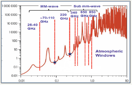
High power terahertz frequencies from 0.1THz to 10THz of the electromagnetic spectrum [1,2] are extensively being investigated over the last 2 decades for numerous applications like ultra-broadband high date rate wireless communication, security, medical imaging, remote sensing, planetary exploration, atmospheric studies, and spectroscopy. As shown in Figure 1, the atmospheric attenuation increases with increase in frequency with additional loss peaks caused by water molecules and other gas molecules. Fortunately, there are many atmospheric windows with low atmospheric loss are available in the THz band, which are being explored for wireless communication. Many R&D labs in India are extensively working on developing efficient and compact high power devices and systems around 94GHz and 220GHz bands [3-5]. Frequency band around 0.22THz is of significant importance for communication because wide atmospheric spectral window is available from 0.20THz to 0.30THz. Ultra wideband communication, remote sensing, imaging applications demand broad bandwidth (>10 GHz) and high power (>10 W) linear devices at THz frequencies. Solid-state devices are not capable to amplify output power more than hundred mW at THz frequencies. Vacuum electronic devices (VEDs) can amplify tens of watts output power at THz frequencies with high efficiency and linearity. Among various vacuum tube amplifiers, travelling wave tube (TWT) is the most preferred choice as a high power THz amplifier for communication and remote sensing due to its high efficiency, wide bandwidth, large RF thermal capacity and high gain. TWTs can have tens of watts amplified output power at such high frequencies with gain 30 dB and efficiency around 5%.
0.22THz 100W PLANAR TWT
figure 2: Schematic of a THz Travelling-Wave Tube with planar RF slow-wave structure and sheet beam.
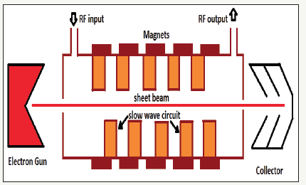
High efficiency, high gain 0.22THz planar TWT, as shown in Figure 2, of output power 100W, gain 30dB and bandwidth more than 30GHz is designed. The electron beam of voltage 20kV and current 100mA is selected considering beam efficiency more than 5%. The major components of a planar TWT are:
a. The electron gun assembly with flat cathode for generation of a rectangular/elliptical sheet electron beam of beam size 100μm (thick) x 600μm (width), at electron beam voltage 20kV and electron beam current 100mA.
b. The RF slow-wave structure (SWS) of wide bandwidth, high impedance, low circuit loss and planar geometry for supporting and amplifying THz waves extracting maximum kinetic energy from the sheet electron beam.
c. The input and the output waveguide couplers to feed THz signal into the circuit and coupled out from the circuit.
d. The periodic permanent magnetic focusing circuit for confined flow of the sheet beam through the structure.
e. The collector for collection of the spent electron beam efficiently with zero back streaming.
f. The packaging of TWT with conduction cooling.
Planar RF structure and sheet beam are preferred for a THz TWT because planar structure is easier to fabricate using MEMS technologies, and sheet beam has higher beam current capacity as compared to pencil beam [6-9]. Sheet beam has very small space charge force as compared to a pencil beam of same beam current, and thereby requiring less magnetic field for beam focussing. Depressed collector is used for recovering kinetic energy from the spent electron beam. TWT for communication is designed for desired RF performance like output power, gain, efficiency, AM/PM factor, gain compression over the desired operating band.
Planar RF Slow-Wave Structure
Simplified analytical approach is developed for designing of a wideband planar RF SWS of a THz TWT [10]. Staggered doublevane rectangular waveguide SWS, as shown in Figure 3, is selected in the present design of a 100W, 0.22THz TWT because it has wide bandwidth and high interaction impedance. Also, it has low circuit loss and it is convenient to fabricate using both MEMS and Nano CNC technologies. There are nine design parameters of a staggered double vane SWS for a given beam voltage. These parameters are: pitch of the vanes (p), staggering factor (d), gap between two vanes (g), vane shape (s), vane thickness (t), vane height (h), beam tunnel height (2a), and height (H) and width (W) of the waveguide. For the vane-loaded SWS, first forward space harmonic (n=+1) of phase shift per pitch (βp) varying from 2π to 3π is selected for TWT operation. TWT operation with the first forward space harmonic (n=+1) provides amplification of RF waves over wider bandwidth and larger size of the structure for given beam voltage. Beam voltage is selected for the synchronous condition with the wave at centre frequency 0.22 THz corresponding to βp equals to (2π+0.5π).
figure 3: Staggered double-vane Slow-Wave Structure with rectangular sheet electron beam.
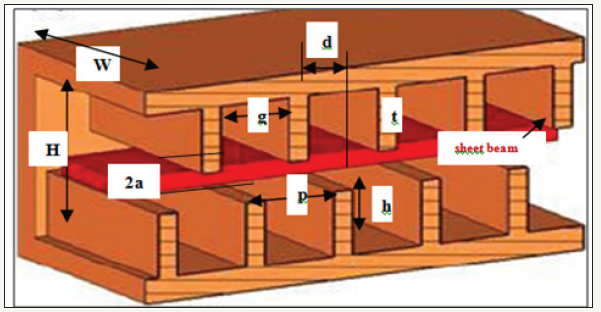
The designed parameters of unit cell of double-vane SWS are summarized in Table 1. The designed parameters of the structure are compared with the published designed data by Deng [11] and Ryskin [12] for a 0.22THz TWT operating at 20kV beam voltage. A very good agreement is achieved in our developed approach with the other latest work for this structure. The vanes loaded on the opposite sides in the waveguide are staggered by half of the period (d=p/2) for wide bandwidth and high impedance of the structure.
Table 1: Parameters of a Unit Cell.
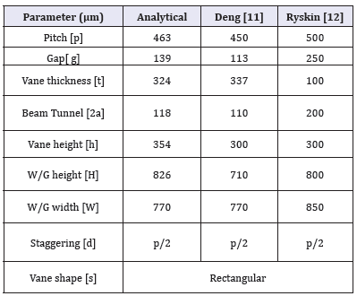
figure 4: Dispersion Curves for Mode 1 and first higher Mode 2 with 20kV electron beam line.
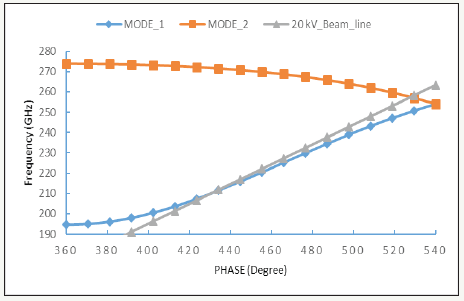
The dispersion curve and the interaction impedance for the analytically designed SDV-SWS are determined by solving the determinant matrix equation (eq. 29) and (eq. 30) of [13,14] respectively. The analytical results for the dispersion curve (normalized phase velocity) and the interaction impedance (averaged across the electron beam) curve corresponding to the +1-space harmonic of the forward wave for the 0.22THz TWT over the frequency range are found comparable with the simulated results using standard 3D e.m. field simulator CST-MWS [15]. For simulating the dispersion and impedance characteristics of the structure of dimension as given in Table 1 using CST code, Eigen mode solver with hexahedral meshing and AKS algorithm method are selected. Simulation was carried out for (n=+1) forward space harmonic of βp varying from 2π to 3π. It has been found from the simulation that half period staggering of vanes provides widest possible bandwidth with high interaction impedance of the structure. Therefore, half period staggered vane-loaded structure is used. Staggered structure (SDV-SWS) has cold bandwidth more than 50 GHz. Dispersion curves for fundamental mode (mode 1) and higher mode (mode 2) are shown in Figure 4. Mode 1 is from 194GHz to 252GHz and Mode 2 is from 252GHz to 274GHz. 20kV beam line as shown in the Figure 4, intersects the dispersion curve at 212GHz. The lower end frequency of the pass band for Mode-1 at phase shift 2π corresponds to the cut-off frequency of the dominant mode TE10 of the rectangular waveguide of width (W). The upper cut-off frequency of mode 1 is decided by the cut-off frequency of mode TE11 (Mode-2).
Table 2: Comparison between Analytical values and CSTMWS values for determined design parameters.

The analytically determined values of βp at 0.22THz, fL, fU and Δf are found comparable with the simulated values using CST-MWS code, as shown in Table 2. This indicates good accuracy of our analytical approach of determining initial design parameters of a unit cell of staggered double-vane rectangular waveguide SWS of a THz TWT.
Large-Signal Analysis
figure 5: a. Electron Beam Representation in 32 Rectangular Discs. b. A Single Rectangular disc.
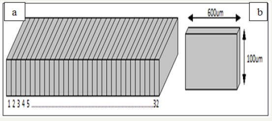
figure 6: Space Charge Force versus Distance for rectangular and equivalent circular discs in equivalent beam tunnels.

The designed 0.22THz TWT with sheet beam was analysed for its RF performance using in-house developed SUNRAY- large-signal analysis code [16,17]. In the developed SUNRAY code for planar TWT with sheet beam, the rectangular sheet beam of one beam wavelength is sliced into number of uniform rectangular discs, as shown in Figure 5. These discs are numerically tracked in small integration steps in presence of the RF circuit field and the space charge field using Runga-Kutta method. Number of rectangular discs and number of the integration steps per wavelength are selected as per the consistency of the output results. The space charge force between 2 rectangular discs in a rectangular tunnel is calculated by solving Green’s Function for an infinite rectangular tunnel of height (a+h/3), and using eq. (1) [18]. Figure 6 shows variation of space charge force between 2 rectangular discs in a rectangular tunnel over one beam wavelength. The SCF between two discs is negligible after half beam wavelength (λe/2=1.85×10-4m). Effective space charge force on a disc is therefore calculated by summing up the SCF on the disc due to all other surrounding discs up to half a beam wavelength. An efficient approach is developed for determining relative disc positions. Also, efficient approach is developed to use look-up table for determining exact value of SCF between 2 discs.
The SCF between two cylindrical discs [16] is significantly more as shown in Figure 6. The dimensions of the cylindrical beam and cylindrical tunnel are selected for same cross-section areas as that of the sheet beam and the rectangular tunnel, respectively.
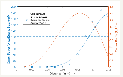
For verifying the numerical accuracy of the SUNRAY code, over a wide dynamic range, the transfer characteristic curves (output power and phase versus drive power) are simulated, as shown in Figure 7. It is found that the power transfer curve is consistent from -100dB below saturation to much beyond 10dB above saturation. The power growth rate is exactly 1dB/dB over the linear region. Also, there is no variation in the phase angle of the output voltage for linear condition. The energy balance factor is found 100% for all drive powers even much beyond saturation indicating high numerical accuracy of the SUNRAY code. Figure 8 shows profiles of the forward growing RF power and normalized RF beam current (I1/I0) along tube length for center frequency 0.22THz, as simulated by SUNRAY code. The growing RF power profile was compared with the published results [19] simulated using CST code. The energy balance profile is also shown and it is 100% throughout the length of the tube.
figure 7: Output Power and Output Phase versus Input drive power.
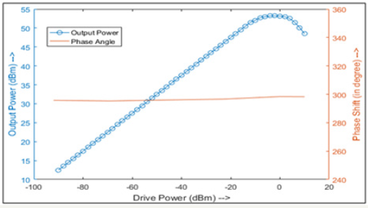
figure 8: RF growing Power, Energy balance and RF beam current Profiles along the structure.
Conclusion
THz waves have unique properties such as non-ionizing radiation with reduced health risks, effective penetration through fabric and fog, and molecular resonances that occur in this frequency band. Therefore, THz waves from 0.1THz to 1THz are highly demanding for medical imaging, safety, defense, remote sensing, spectroscopy and for ultra broadband wireless communication. Development activities addressed to 0.22THz centre frequency is of significant importance for ultra wide band communication, imaging and remote sensing because of the available atmospheric spectral window over wideband from 0.20THz to 0.30THz. Compact vacuum electronic devices are being investigated of high output power, high gain and high efficiency at THz frequencies. Among various vacuum devices, TWT is preferred as a high power amplifier due to its wide bandwidth and high linearity. THz TWT of centre frequency 0.22 THz, 100 W output power, 30 dB gain, 5-10% efficiency and more than 30 GHz bandwidth is being investigated for high data rate wireless communication, imaging and remote sensing.
Acknowledgement
Author is thankful to the Director, CSIR-CEERI, Pilani, and his colleagues of MWT Div., for many helpful supp carried out orts. The useful research contributions by his research students Dr PC Panda, Deepak Sharma and Aakash Bansal with him are thankfully acknowledged.
References
- Ian F Akyildiz,Josep Miquel Jornet, ChongHan (2014) Terahertz band: Next frontier for wireless communications.Physical Communication Journal 12: 16-32.
- Booske JH, Dobbs RJ, Joye CD,Kory CL,Neil GR, et al.(2011) Vacuum electronic high-power terahertz sources. IEEE Trans. on Terahertz Science and Technology 1: 54-75.
- Srivastava V (2008), THz Vacuum microelectronic devices, Journal of Physics 114:1-10.
- Sharma RK, Grede A, Srivastava V, Henke H (2014) Design of folded waveguide SWS for W-Band TWT. IEEE Trans. Plasma Sci 42:3430-3437.
- Srivastava A (2015) Microfabricated terahertz vacuum electron devices. European Journal of Advances in Engineering and Technology 2: 54-64.
- Shin YM (2012) System design analysis of a 0.22THz sheet-beam travelling-wave tube amplifier.IEEE Trans. Electron Devices 59(1): 234- 239.
- JanA Baig, Barnett LR, Gamzina D, Luhmann NC (2013) MEMS compatible sever for 220 GHz ultra wide band TWTA: design and particle-in-cell analysis. Progress in Electromagnetic Res. Letter 41: 135-148.
- Shu G, Wang J, Liu G, LuoY,Wang S (2016) An improved SWS for sheetbeam travelling-wave tube. IEEE Trans. Electron Devices 63: 2089-2097.
- Panda PC, Srivastava, Vohra A (2013) Staggered closed PCM for stable sheet electron beam transport.IEEE Trans. Electron Devices 60(9): 2918-2923.
- Srivastava V, Sharma DK (2017) Design of broadband planar SWS for 0.22-THz TWT. Universal Journal of Electrical & Electronics Engg 5: 9-19.
- Deng G, Chen G, Yang J, Yin Z, Ruan (2016) 0.22 THz two-stage cascaded staggered double-vane traveling-wave tube, Journal of Computational Electronics 15(2): 634-638.
- Ryskin NM, Karetnikova TA, RozhnevAG, Shalaev PD (2015) Development and modeling of a sheet-beam sub-THz TWT. Procof the IEEE International Vacuum Electronics Conference, USA.
- Xie W, Zi Cheng, J Luo, Q Liu (2014)Theory and Simulation of Arbitrarily Shaped Grooved Staggered Double Grating Array Waveguide. IEEE Transactions on Electron Device 61: 6.
- X Lei, Y Wei, Y Wang, Q Zhou, G Wu, et al. (2017) Full-wave Analysis of the High Frequency Characteristics of the Sine Waveguide Slow-Wave Structure. AIP Advances 7: 085111.
- CST – Computer Simulation Technology (2018) Dassault Systemes, France.
- V Srivastava (2013) SUNRAY-1D and SUNRAY-2.5D codes for large signal analysis of TWT.In: Proceedings of the IEEE International Vacuum Electronics Conf, USA.
- V Srivastava (2017) Nonlinear analysis of beam-wave interaction in a planar THz travelling-wave tube amplifier.Journal of Electromagnetic Waves and Application 32: 190-203.
- C Fu, Y Wei, B Zhao, Y Yang, Y Ju (2016) One-Dimensional nonlinear theory for rectangular helix traveling-wave tube. AIP Physics of Plasma 23: 083123.
- H Yin, J Xu, L Yue, Y Gong, Y Wei (2012) A Method to Calculate Output Power for Sheet-Beam Traveling Wave Tube. IEEE Trans. on Electron Devices 59: 3630-3634.
© 2018 Vishnu Srivastava. This is an open access article distributed under the terms of the Creative Commons Attribution License , which permits unrestricted use, distribution, and build upon your work non-commercially.
 a Creative Commons Attribution 4.0 International License. Based on a work at www.crimsonpublishers.com.
Best viewed in


.jpg)


 Editorial Board Registrations
 Submit your Article
 Refer a Friend
 Advertise With Us
.jpg)


.jpg)


.bmp)
.jpg)
.png)
.jpg)


.jpg)


.png)

.png)


.png)


