- Submissions

Full Text
Aspects in Mining & Mineral Science
Three Essential Steps in Metallurgical Design of Solid Wire Electrodes for High Strength Steels
Sampath K*
Santa Clara, USA
*Corresponding author:K Sampath, Santa Clara, CA 95054, USA
Submission: June 14, 2025: Published: August 29, 2025

ISSN 2578-0255Volume14 Issue 1
Abstract
In 1991, Electric Boat at Connecticut built the hull for the first Seawolf submarine using HY-100 High Strength Steel (HSS). The nominal Carbon content of HY-100 steel is between 0.12 and 0.20 wt-%. When the Carbon content exceeds 0.12 wt-%, the morphology of martensite is likely to change from needles to plates [1,2], and this morphological change in the weld Heat Affected Zone (HAZ) microstructure is known to adversely affect both Charpy V-Notch (CVN) impact toughness and/or fracture toughness besides increasing the sensitivity to Hydrogen-Induced Cracking (HIC). Between June and July of 1991, several micro-cracks related to HIC were found in the hull of the first Seawolf submarine. Professor Thomas W. Eagar at Massachusetts Institute of Technology evaluated the underlying problem. He reported that lubricant contamination on the surface of the solid wire electrode used in Gas Metal Arc Welding (GMAW) was one of two primary causes [3]. The second primary cause was the high Carbon content of the solid wire electrode, but the Carbon content was at the high end of the relevant solid wire electrode specification limits such as MIL-E-23765/2E [4] and AWS A5.28 Specification for Low-Alloy Steel Electrodes and Rods for Gas Shielded Arc Welding [5].
Keywords:Carbon; Solid wire electrode; Welding; Plate steels; Microstructures
Introduction
The cracking was likely induced by the presence of hydrogen in the welds, which pinpointed the lubricant as a likely source of hydrogen during the manufacture of the solid wire electrode. US Navy, in its official statements on the cause of micro-cracking, noted the high Carbon content of the solid wire electrode, but never listed lubricant contamination as a factor. L-TEC, an Ohio company that manufactured and supplied the solid wire electrode for the first Seawolf submarine, declined to comment [3] at that time. Although the hull of the first Seawolf submarine was made entirely of HY-100 steel, the same type of steel had been used for various parts in US Navy surface ships since the 1960s. In particular, for primarily demonstration purposes the hull sections of two 688-class attack submarines - the Topeka, was built by Electric Boat and commissioned in 1989. Albany was built by Newport News Shipbuilding & Dry Dock Co. and commissioned in 1990. US Navy officials reported they were confident the hulls of Topeka and Albany were sound because they were welded with a solid wire electrode with a lower Carbon content [3] than the L-Tec manufactured solid wire electrode used in fabricating the hull of the first Seawolf submarine. Furthermore, US Navy reported the weld micro-cracks resulted from a confluence of a number of worse-case conditions not previously experienced in welding HY-100 steel. Primarily these involved the use of a higher Carbon content in solid wire electrode with a welding procedure that seemed to allow an unacceptably faster weld cooling rate [3].
Prof. Thomas Eagar recommended the following actions to guard against HIC in rebuilding the submarine:
a. Use welding wire with a lower Carbon content.
b. Surface clean the wire, if practical, to remove any contamination.
c. Increase the preheat and interpass temperature of HY-100 steel prior to welding in order to allow hydrogen to escape the weldment.
d. Continue to heat the area around the weld after the weld is completed, to slow down the cooling rate, again allowing hydrogen to disperse; and
e. Establish a “clean” specification to address surface contamination of solid wire electrode.
Prof. Thomas Eagar also recommended that US Navy consider producing its own welding wire [3], as it was simply not clear that commercial welding consumable manufacturers would devote adequate attention and resources necessary to create a high-quality product required by US Navy. In fact, US Naval Surface Warfare Center at Carderock (NSWC-CD), MD, USA produced over 160 solid wire electrode compositions in its laboratory and did appropriate weld testing. The related weldments met either the yield strength or CVN impact toughness, but not both simultaneously. Furthermore, Alloy Rods Global, Inc., (now ESAB) also produced several solid wire electrodes, and patented the related solid wire electrode compositions in US Patent 5523540 [6]. However, the weldments reported in US Patent 5523540 met either the yield strength or the toughness, but not both simultaneously.
Objective
The above set of results emphasize that welding electrode designers must avoid “trial-and-error” methods; instead address research gaps that correlate metallurgical fundamentals in terms of chemical composition-processing-microstructure and mechanical properties in developing solid wire electrodes for HSSs such as HY-100, HSLA-100, HY-80, HSLA-80, etc., used in US Navy aircraft carrier and submarine construction.
Constraints-Based Modeling
Following the above first Seawolf submarine incidence, a set of advanced ER-100S and ER-120S (MIL-100S and MIL- 120S equivalents) solid wire electrodes was developed for GMA welding of HSS, including HY-100 and HSLA-100 steels, to ensure high-performance including successful ballistic welding testing. Compared to the nominal Carbon range of 0.12 and 0.20 wt-% in HY-100 steel, the nominal Carbon content of HSLA-100 steel is below 0.06 wt-%. Any welding electrode designer needs to consider the effects of base metal dilution of either HY-100 or HSLA-100 to further enable successful navigation of welding electrode specifications in either developing or ascertaining superior combination of weld metal yield strength and CVN impact toughness. The above successful effort employed the following 3 specific aspects.
First, initial effort consolidated existing metallurgical knowledge on chemical composition-processing-microstructure development and mechanical properties of both HY-100 and HSLA-100 plate steels. Fundamentally, an understanding of the interactive effects of both major (C, Si, Mn, P, S, Cu, Ni, Cr and Mo) and minor (Nb or Cb, V, Zr, Ti, B, Al, N and O) alloy additions in HSS weld metals, including the effects of base metal dilution in weldment of either HY-100 or HSLA-100 are necessary to enable welding electrode designers to successfully navigate through welding electrode specifications.
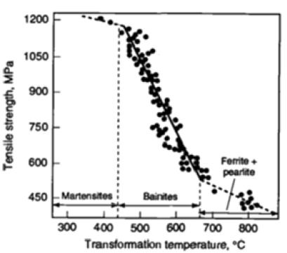
Figure 1 illustrates the fundamental relationship between austenite decomposition (i.e., transformation) temperatures and tensile strength of regularly processed steels with 3 types of resultant predominant microstructures [7] viz., ferritic-pearlitic, bainitic, and martensitic that are related to certain numerical ranges for austenite-transformation temperatures such as Ar3 (ferritestart), BS (bainite-start) and MS (martensite-start). Despite scatter in the published results shown in Figure 1, welding electrode designers could readily recognize that the slope of the nominal linear relationship between transformation temperatures (in °C) and tensile strength (in MPa) of ferritic-pearlitic steels is different from that of bainitic steels, which is further different from that of martensitic steels.
Suppressing various austenite decomposition (TS) temperatures is known to induce greater nucleation rates and refine resultant microstructural constituents [8]. In order to suppress various TS temperatures, the welding electrode designers could use two means: 1) proper control of the major alloying elements such as C, Si, Mn, P, S, Cu, Ni, Cr and Mo and minor alloying elements such as Nb or Cb, V, Zr, Ti, B, Al, N and O in chemical composition of Fe-C-Mn electrode and weld metals; and 2) increase weld cooling rate between 800 and 500 °C (i.e., Dt8/5) to obtain significant undercooling.
Second, welding electrode designers need to reach beyond existing knowledge on electrode development and in particular avoid the selection of “rich” and “lean” compositions within the required chemical composition range of the relevant electrode specifications [4,5]. A “rich” composition refers to all or most principal alloy elements such as C, Mn, Ni, Cr, Mo, and Cu at or near the top of the welding electrode specification range, while a “lean” composition refers to all or most of the above principal elements at or near the bottom of the welding electrode specification range. Based on the lessons learned regarding the effect of “rich” electrode composition on the cracking of the hull of the first Seawolf submarine in June and July 1991 [9] built with HY-100 steel, welding electrode designers must avoid the selection of “rich” compositions within the required electrode specification range that could provide unusually high-strength weld metal at low-energy input welding conditions. Similarly, welding electrode designers must also avoid the selection of “lean” compositions within the required electrode specification range that could provide abnormally poor strength weld metal at high-energy input welding conditions.
Third, instead of “trial-and-error” methods, the welding electrode designers could possibly employ a Constraints-Based Model (CBM) to stipulate a set of “mutually inclusive” boundary conditions. Specifically, the various constraints or “mutually inclusive” boundary conditions refer to selection of numerical ranges for austenite-transformation temperatures such as Ar3 (ferrite-start), BS (bainite-start) and MS (martensite-start) besides Carbon content below 0.10 wt-% and 9 other elemental alloy content though Yurioka’s [10] Carbon Equivalent Number (CEN) to obtain desired combination of microstructures in the weld metal. Commonly, Yurioka’s CEN [10] is used to evaluate the weldability of a variety of structural and pressure vessel steels, particularly, to assess the need for preheat to overcome HIC.
With the application of CBM, Yurioka’s CEN is also used to identify welded metals that overmatch weld metal tensile strength relative to base metal tensile strength thus ensuring a joint efficiency in excess of 100% while complying with chemical composition requirements of relevant welding electrode specifications [4,5] for HSSs.
Yurioka’s CEN=C+{A(C)×EMU} (Equation 1)
where A(C) refers to the Accommodation factor that is a function of Carbon content, while EMU refers to an elemental multiplication unit involving the following 9 elements: Si, Mn, Cu, Ni, Cr, Mo, V, Nb (Cb) and B.
A(C)=0.75+0.25 tanh [20×(C–0.12)] (Equation 2)
EMU={Si/24+Mn/6+Cu/15+Ni/20+(Cr+Mo+V+Nb)/5+5xB} (Equation 3)
Here, Yurioka’s CEN [10] involves a total of 10 elemental additions, indicating that Yurioka’s CEN is more comprehensive. Depending on the preferences of welding electrode designers, instead of Yurioka’s CEN, one could use an alternate carbon equivalent formula such as CEIIW, Pcm etc. particularly when both Nb and V are not simultaneously present to ensure that the weld metal overmatched the minimal strength requirements of relevant HSS base metal such as HY-100, HY-80, HSLA-100, HSLA-80, etc. Normally, Carbon equivalence is directly correlated with Ultimate Tensile Strength (UTS) of a set of HSSs. This is based on any one type of Fe-C-Mn alloy system with “nearly” identical material processing.
Control of calculated austenite Transformation-Start (TS) temperatures such as Ar3, (Ferrite-Start), BS (Bainite-Start), or MS (Martensite-Start) besides Carbon content, Yurioka’s CEN appear necessary supplements in achieving weld metals with high performance. These Calculated Metallurgical Characteristics (CMCs) are related to the chemical composition of HSS thru the statistical (regression) equations listed below:
Ar3(°C)=910–(310xC)–(80xMn)–(80xMo)–(55xNi)–(20xCu)– (15xCr) (Equation 4)
BS(°C)=830–(270×C)–(90×Mn)–(37×Ni)–(70×Cr)–(83×Mo) (Equation 5)
B50(°C)=BS (°C)-60=770–(270×C)–(90×Mn)–(37×Ni)–(70×Cr)– (83×Mo) (Equation 6)
BF(°C)=BS(°C)-120=710–(270×C)–(90×Mn)–(37×Ni)–(70×Cr)– (83×Mo) (Equation 7)
MS(°C)=561–(474×C)–(33×Mn)–(17×Ni)–(17×Cr)–(21×Mo) (Equation 8)
In general, the CMCs based on the above equations provide approximate, but not exact valuations of various TS temperatures. In particular, the CMCs of most weld metals are also dependent on weld cooling rate, and must also show a progressive decrease in calculated values of various TS temperatures, with Ar3 >BS >MS. When weld metals show a progressive decrease in the calculated TS temperatures as in Ar3>Bs>Ms, depending on the actual weld cooling rate, welding electrode designers can expect to obtain predominantly diffusional transformation products from austenite decomposition [11] instead of a thermal transformation product.
CBM identifies and simultaneously solves the above set of regression equations in a “mutually inclusive” fashion to meet certain numerical ranges or specific boundary conditions for CMCs such as CEN, Ar3, BS, BF, and MS related to chemical composition and specific microstructural characteristics of interest as shown in Figure 1. The constraints and their numerical ranges themselves underscore the metallurgical criteria that depending on the desired combination of weld metal microstructure such as acicular ferrite [12], low-C bainite [13,14], or lath martensite [15], welding electrode designers need to lower the relevant solid- state TS temperatures to improve weld metal strength and fracture toughness while simultaneously reducing Carbon content [16] but overmatching Yurioka’s CEN [10] with that of base metal(s) being joined to ensure improved weldability at required level of overmatching of the tensile strength of the weldment.
Figure 1:Relationship between tensile strength (in MPa) and transformation temperature (in °C) of ferriticpearlitic, bainitic, and martensitic steels [7].

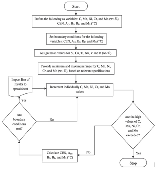
The various calculations associated with this metallurgical and mathematical modeling can be performed using either a scientific calculator, commercially available Microsoft Excel or similar software, or a suitably designed computer software program. Figure 2 shows a typical flowchart [17,18] that can be used to identify electrode or weld metal compositions with desired minimum and maximum ranges of limits as detailed in the boundary conditions for various elements within the relevant electrode specification [4,5] and the boundary conditions for desired CMCs of weld metal. Additionally, the flowchart allows one to assign mean values for selected elements such as Ti, Al and O besides Si, Cu, Nb, V, B that are considered vital for promoting specific types of microstructures, even though Ti, Al, and O elements do not appear in Eqs. (1)-(8) for calculating relevant CMCs.
Figure 2:A typical flowchart used with computer programming associated with CBM [17,18].

A recent research publication shows how one could apply CBM in relating to weld metal composition with the formation of predominantly acicular ferrite in weld metal microstructure [19]. Depending on the value of TS temperature, at about 690 °C±40 °C as a desirable target range, with Ti:B ratio held near 10:1, the total “balanced” Ti-B-Al-N-O additions could be held between 0.05 wt-% and 0.06 wt-% in achieving a significant spread between Yield Strength (YS) and Ultimate Tensile Strength (UTS) of weld metal while ensuring the YS/UTS ratio between 0.84 and 0.92 to provide a superior combination of excellent ductility and low-temperature impact (fracture) toughness.
Results
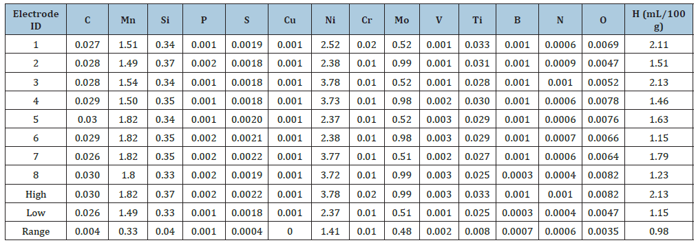
Application of CBM as a computational tool eliminated conventional “trial-and-error” methods and resulted in the development of a set of advanced ER-100S and ER-120S (MIL- 100S and MIL-120S equivalents) electrodes. These bare solid wire electrodes for GMA welding ensured high-performance weldments in HSSs, including both HY-100 and HSLA- 100 steels used in US Navy submarine and aircraft carrier construction. Following the award of US Patent 5744782 [20] in April 1998, the actual chemical compositions of these 8 experimental bare solid wire electrodes (Table 1) were described in detail.
These 8 bare solid wire electrodes were based on a 23 Taguchi design. The 23 Taguchi design varied the contents of only three principal alloy elements, viz., Manganese, Nickel, and Molybdenum, each at 2 levels, one “high” and the other “low,” while keeping all other elements at a fairly constant level. Vacuum Induction Melting (VIM) was used to produce various billets corresponding to the 8 bare solid wire electrode manufacturing, all in one-go [21], thus eliminating conventional “trial-and-error” methods. Use of VIM limited the total gas content much below 500 ppm and eliminated any adverse effect of gaseous elements on weld metal toughness. The resulting weld metals showed a predominantly low-Carbon bainitic microstructure [22] that was also insensitive to HIC.
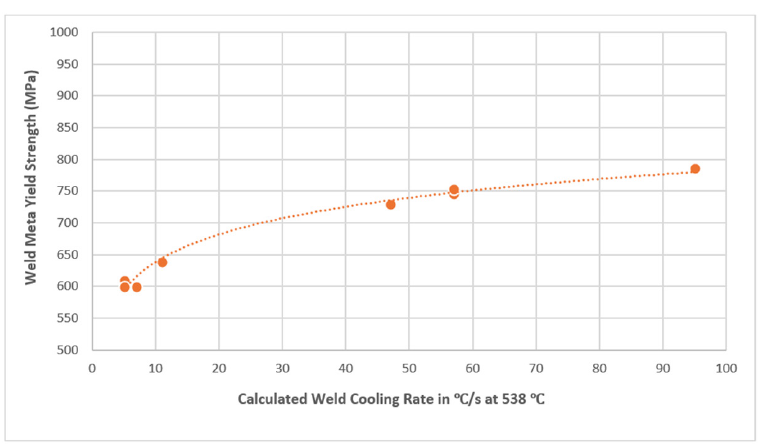
One of the bare solid wire electrodes (#3 in Table 1 with 0.028 wt-% C, 1.54 wt-% Mn, 3.78 wt-% Ni, 0.52 wt-% Mo, 0.34 wt-% Si, 0.01 wt-% Cr, 0.028 wt-% Ti, 0.0001 wt-% B, O at 52 ppm, N at 10 ppm, with H at 2.13 mL/100 g, and with the following CMCs: Yurioka’s CEN = 0.32; calculated B50 = 440 °C, calculated MS = 422 °C) was used in additional evaluations of a set of 8 GMA weldments [20], including successful ballistic weld testing, as per US Navy requirements. The eight GMA weldments were produced in 25.4-mm (1-in)-thick HY-100 and HSLA-100 steel plates using a wide range of shipyard fabrication conditions that represented calculated weld cooling rates ranging between 3 and 53 °C/s at 538 °C (i.e., 1000 °F). The weld cooling rates were calculated using the procedure outlined by Jhaveri P et al. [23]. As shown in Figure 3, these 8 weldments revealed acceptable variation in weld metal yield strength with calculated weld cooling rate at 538 °C [21,23], in line with US Navy requirements for both yield strength and CVN impact toughness. The trend line showed the following statistical relationship, at a r2 value of 0.99:
Weld metal yield strength (in MPa)=542.6×(Calculated weld cooling rate at 538 ∘C)0.0925 (Equation 9)
Table 1:Chemical composition (in wt-%) of 8 experimental solid wire GMAW electrodes based on 23 Taguchi design [20].

Figure 3:Variation of yield strength of HSS weld metal with calculated weld cooling rate [21,23].

Thus, the use of CBM approach in successfully developing highperformance solid wire electrodes for GMA welding of HY-100 and HSLA-100 steels per relevant military standards [4] substantially minimized risk, eliminated “trial-and-error” methods, significantly reduced electrode development cost while meeting stringent schedule requirements. To this date, no other ER-100S (or MIL- 100S equivalent) solid wire electrode has been known to match this achievement!
Conclusion
Constraints Based Modeling, based on a set of equations that relate to CMCs, is an extremely valuable tool in developing solid wire electrode for HSSs such as HY-100 and HSLA-100. Relevant examples cited in US Patent 5744782 [20] reveal that CBM allows one to address essential research gaps thereby correlate metallurgical fundamentals in developing solid wire electrodes for HSSs, substantially minimize risk, eliminate “trial-and-error” methods, significantly reduce electrode development cost while enabling to meet stringent schedule requirements.
References
- Sugiyama M, Sawa G, Hata K, Maruyama N (2019) Heterogeneous microstructure of low-carbon lath martensite with continuous yielding behavior in Fe-C-Mn alloys. IOP Conf Ser: Materials Science and Engineering 580: 012045
- Jorge JCF, de Souza LFG, Mendes MC, Bott IS, Araúj LS et al. (2021) Microstructure characterization and its relationship with impact toughness of C-Mn and high strength low alloy steel weld metals - A review Journal of Materials Research and Technology10: 471-501.
- (1991) Hartford Courant, Tainted Wire is Blamed for Cracks in Sub.
- MIL-E-23765/2E (1994) Military Specification: Electrodes and Rods-Welding, Bare, Solid, or Alloy Cored; and Fluxes, Low Alloy Steel.
- 28 Specification for Low-Alloy Steel Electrodes and Rods for Gas Shielded Arc Welding, 2022. American Welding Society (AWS), Florida, USA.
- Coldren AP, Fiore SR, Smith RB (1996) Welding electrodes for producing low carbon bainitic ferrite weld deposits. U S Patent 5523540.
- Pickering FB (1978) Physical metallurgy and the design of steels. Applied Science Publishers p. 106.
- Bhadeshia HKDH (2007) Frontiers in the modelling of steel weld deposits. J Jpn Weld Soc 76(2): 24-30.
- Schank JF, Murphy RE, Arena MV, Kamarck KN, Lee GT, et al. (2011) Learning from experience: Lessons from the U S Navy's Ohio, Seawolf, and Virginia Submarine Programs, RAND Corporation (II): 43-60.
- Yurioka N, Suzuki H, Ohshita S, Saito S (1983) Determination of necessary preheating temperature in steel welding. Welding Journal 62(6): 147-153.
- Sampath K (2021) Analysis of a high-strength steel SMAW database. Welding Journal 100(10): 410-420.
- Fujiyama N, Shigesato G (2021) Effects of Mn and Al on acicular ferrite formation in SAW Weld Metal. ISIJ International 61(5):1614-1622.
- Seo JS, Kim HJ, Lee C (2013) Effect of Ti addition on weld microstructure and inclusion characteristics of bainitic GMA welds. ISIJ International 53(5): 880-886.
- Seo JS, Lee C, Kim HJ (2013) Influence of oxygen content on microstructure and inclusion characteristics of bainitic weld metals. ISIJ International 53(2): 279-285.
- Fairchild DP, Koo J, Bangaru NV, Macia ML, Beeson DL, et al. (2003) Weld metals with superior low temperature toughness for joining high strength, low alloy steels 6565678.
- Sampath K, Varadarajan R (2023) High strength steel weld metal properties: metallurgical criteria and computational tools. Welding in the World 67(7): 2081-2105.
- Sampath K, Varadan R (2006) Evaluation of chemical composition limits of GMA welding electrode specifications for HSLA-100 steel. Welding Journal 85(08): 163-173.
- Sampath V, Kehl J, Vizza C, Varadan R, Sampath K (2008) Metallurgical design of high-performance GMAW electrodes for joining HSLA-65 steel. J Mater Eng Perform17(6): 808-830.
- Sampath K (2024) Selective analysis of a high-strength steel shielded metal arc weld metal database. Aspects Min Miner Sci 12(4): 2578-0255.
- Sampath K, Green RS (1997) Advanced consumable electrodes for gas metal arc (GMA) welding of high strength low alloy (HSLA) steels. 5744782.
- Sampath K (2005) Constraints-based modelling enables successful development of a welding electrode specification for critical navy applications. Welding Journal 84(8): 131-138.
- Sampath K, Green RS, Civis DA, Dong H, Konkol PJ (1995) Evaluation of new high-performance electrodes for GMA welding of HSLA-100 steel, in High Performance Structural Steels, In: Asfahani R (Ed.), ASM International Materials Park OH pp. 179-188.
- Jhaveri P, Moffatt WG, Adams CM (1962) The effect of plate thickness and radiation on heat flow in welding and cutting. Welding Journal 41(1): 12-16.
© 2025 Sampath K. This is an open access article distributed under the terms of the Creative Commons Attribution License , which permits unrestricted use, distribution, and build upon your work non-commercially.
 a Creative Commons Attribution 4.0 International License. Based on a work at www.crimsonpublishers.com.
Best viewed in


.jpg)


 Editorial Board Registrations
 Submit your Article
 Refer a Friend
 Advertise With Us
.jpg)


.jpg)


.bmp)
.jpg)
.png)
.jpg)


.jpg)


.png)

.png)


.png)


