
- About Us
- Information
-

The Author ensures that the research has been conducted responsibly and ethically with adherence to all relevant regulations. read more..
- For Authors
- For Reviewer
- Manuscript Guidelines
- Membership
- Publication Ethics
-
- Journals
- Reprints
- e-Books
- Videos
- Policies
- Contact Us
 COVID-19
- Submissions


Full Text
Aspects in Mining & Mineral Science
An Overview of Conventional Techniques and Recent Advancements in CO2 Capture Technologies
Waqad Ul Mulk*
Department of Mechanical Engineering, Universiti Teknologi PETRONAS, Malaysia
*Corresponding author:Waqad Ul Mulk, Department of Mechanical Engineering, Universiti Teknologi PETRONAS, 32610 Bandar Seri Iskandar, Perak Darul Ridzuan, Malaysia
Submission: April 28, 2023; Published: May 17, 2023

ISSN 2578-0255Volume11 Issue3
Abstract
CO2 Capture and Utilization (CCU) is a promising technique for reducing global warming. Conventional methods include absorption and adsorption, chemical looping combustion and cryogenic distillation, hydrate-based separation and membrane separation have been used for CO2 separation, but they have certain limitations like high energy intensive, solvent degradation, solvent loss, corrosive nature of the solvents and toxicity of solvents. Novel materials and techniques are always being developed in order to achieve greater optimization. Ionic Liquids (ILs) have demonstrated great potential for cost-effective CO2 separation. Similarly, Supported Ionic Liquid Membranes (SILMs) have also shown effective CO2 separation performance. This review offers the detailed mechanism, advantages and disadvantages and comparison of various conventional methods used for CO2 capture. In addition, different ionic liquids used for CO2 separation have also been discussed in detail. Lastly, Various challenges, and future recommendations in SILMs are identified and explained.
Keywords:Conventional technologies for CO2 capture; Ionic liquids; SILM; CO2/N2 permeability and selectivity
Abbreviations:CO2: Carbon Dioxide; N2: Nitrogen; H2O: Water; CH4: Methane; H2: Hydrogen; GPU: Gas Permeation Unit; IL: Ionic Liquid; TSIL: Task-Specific Ionic Liquid; RTIL: Room-Temperature Ionic Liquid; SLM: Supported Liquid Membrane; SILM: Supported Ionic Liquid Membrane; PF6: Hexafluorophosphate; Tf2N: Bis(trifluoromethylsulfonyl)-amide; BF4: Tetrafluoroborate; C2mim: 1-ethyl-3-methyl-imidazolium; C4mim: 1-butyl-3-methyl-imidazolium; C8mim: 1-octyl-3-methyl-imidazolium; DCA: Dicyanamide; Gly: Alanate; P66614: Trihexyl(tetradecyl)phosphonium; PI: Polyimide; PVDF: Polyvinylidene Fluoride; PS: Polysulfone; PES: Polyether Sulfone; PTFE: Poly (Tetrafluoroethylene); MMM: Mixed Matrix Membrane; GHG: Greenhouse Gases; CCU: Carbon Capture and Utilization; C5H6NCl: Pyridinium Chloride; H4P+: Phosphonium; NH4+: Ammonium; Gt: Gigatonnes; IGCC: Integrated Gasification Combined Cycle; ASU: Air Separation Unit; MEA: Mono-Ethanolamine; HSO4−: Hydrogen Sulfate; CILs: Conventional Ionic Liquids; [bmim][PF6]: 1-Butyl-3-methylimidazolium hexafluorophosphate; [bmim][Tf2N]: 1-Butyl-3-methylimidazolium bis[trifluoromethyl)sulfonyl]- imide; [bmim][BF4]: 1-butyl-3-methylimidazolium tetrafluoroborate; [bmim][Ac]: 1-butyl-3-methylimidazolium acetate; [bmim][DCA]: 1-butyl-3-methylimidazolium dicyanamide; [bmim][TCM]: 1-butyl-3-methylimidazolium tricyanomethanide; [bmim][NO3]: 1-Butyl-3-methylimidazolium nitrate; [Bmim][Gly]: 1-butyl-3-methylimidazolium glycinate; [Bmim][Ala]: 1-butyl-3-methylimidazolium L-alaninate
Introduction
Human activities and natural processes contribute to the emission of greenhouse gases like carbon dioxide, nitrous oxide, methane, and halogenated compounds. GHGs absorb infrared radiation and trap heat within the atmosphere, increasing the natural greenhouse effect known as global warming. The amount of CO2 emissions is around 15-20% in the atmosphere and a major contributor in the greenhouse gases [1]. The CO2 emissions from energy related sources of the United States, Japan and European Union declined significantly in 2019, compared with the previous year 2018, but emissions in the rest of the world increased by a same amount which levelling off the overall CO2 emissions [2]. The main problem of the environment today is the maximum CO2 emissions which induce global warming as a result. The earth’s climate is differing constantly because of different factors, viz., change in the Sun’s intensity, and change in the Earth’s orbit, volcanic emissions, and increase in Greenhouse Gas (GHG) concentrations. The increase in the earth’s temperature is due to the phenomenon where carbon dioxide (CO2), methane (CH4) and other anthropogenic gases absorb the leaving infrared radiations which cause an increase in the temperature of earth [3]. For industrial CO2 emissions, various Carbon Capture and Storage (CCS) systems are in the development stage. Precombustion, post-combustion, and oxyfuel combustion are the three main CCS methods. The mitigation of CO2 before combustion, which relates to the gasification process to create synthesis gas, is referred to as pre-combustion capture. After that, the synthesis gas can be treated to create H2 and CO2 rich streams or converted into chemicals and light fuels by catalysis [4,5]. The oxyfuel combustion method needs the use of pure oxygen for the fuel combustion [6]. Existing plants cannot use either pre-combustion or oxyfuel combustion methods. Post-combustion CO2 separation methods, on the other hand, may be retrofitted onto existing facilities [7]. Cryogenic separation, amines solvent based absorption, porous solids based adsorption, and membrane separation are all employed in post-combustion CO2 separation procedures for gas processing and CO2 capture, respectively [8]. The use of amines to capture CO2 by post-combustion is a robust approach that may be integrated into existing plants [9]. Despite its great efficiency, the aminebased CO2 separation technology is neither a long-term ecologically friendly or cost-effective option [10]. Solvent degradation [11,12], equipment corrosion [13,14], solvent escape, and the production of nitrosamines and nitramines are all disadvantages of amine-based chemical solvents [15].
In this work, the conventional methods used for CO2 separation are comprehensively presented. The mechanism, advantages and disadvantages and comparison of the conventional methods, i.e., absorption and adsorption process, chemical looping combustion, cryogenic distillation, hydrate-based separation, and membrane separation are broadly explained. Ionic liquids, being an attractive solvent with excellent properties are discussed in detail. The use of ILs in combination with membranes is a relatively recent technology for gas separation explored in the last two decades. Supported Ionic Liquid Membranes (SILMs) is among the many forms of IL-containing membranes reviewed in this study.
Sources of CO2 Emissions
Worldwide anthropogenic (GHG) emissions are predominantly because of human activities that includes the consumption of nonrenewable energy resources, transportation, industrial processes and emissions from forestry and other land use [16]. According to the Figure 1, the data was published by the European Environment Agency in 2016 and it shows that, among various sources of anthropogenic (GHG) emissions, the fuel combustion sector mainly use for electricity and heat production has the biggest commitment towards greenhouse gas emissions. Similarly, the transport sector has also shown the excess amount of GHG emissions followed by Industrial processes and Agriculture sector [16]. As reported by Netherlands Environmental Assessment Agency In 2018, the development altogether worldwide ozone depleting substance (GHG) emissions (eliminating those from land-use change) continued at pace of 2.0%, coming to 51.8 gigatonnes of CO2 equivalent [17]. Similarly, the increase in global GHG emissions of 2% (1.0 gigatonnes CO2) was due to a 2.0% rise in worldwide CO2 emissions from fossil fuel combustion and from Industrial processes together with cement production. There was a 1.8% increase in global methane and 0.8% increase in global nitrogen oxide emissions during the same time period [18]. In the 1990s, global fossil fuel CO2 emissions increased by 0.9 percent per year. In the 2000s, they accelerated to a rate of 3.0 percent per year. Since 2010, they have returned to a slower growth rate, increasing by 0.9 percent per year [19]. Aside from declines in emissions in the European Union and the United States over the last decade, the rise in emissions in China, India, and most emerging nations had also greatly affected global emission trends over the last couple of decades [20].
Figure 1:Greenhouse gas emissions by sectors 2016 [16].

The study used a large cassiterite crystal of about 40x20mm (Sample Sn-70 from the Prinzler countervein (Puffe, 1936)). The root zone contains tiny topaz crystals (about 2mm in diameter). Besides cassiterite and topaz, there are a lot of other minor minerals: plagioclase, albite, kumdykolite, calcite, fluorite, graphite, rynersonite, mangancolumbite, uraninite, monazite, xenotime, moissanite, diamond, Ti-carbides. The last three minerals are generally associated with small black elliptical aggregates in topaz. The sample contains in muscovite tiny cassiterite crystals with a clear rhombic cross-section (Figure 1). Larger crystals have no precise crystallographic forms (Figure 2).
In 2019, Global greenhouse gas emissions increased at a 1.1%, reaching 52.4 Gt CO2 comparable. The main reason for the rise in global greenhouse gas emissions coincided with the rise in global carbon dioxide emissions in 2019. Similarly, the global emissions of Methane increased by 1.3%. This results in CO2 from fossil fuels accounts for 73% of the total, while methane accounts for 19%. contributed mainly to the rise of global warming [21]. As stated in Figure 2, the International Environment Agency did a study in 2021 and compared the Global CO2 emissions in the last three decades. Stated that the worldwide CO2 emissions was nearly 21 gigatonnes in 1990 and then grew up continuously to almost 33 gigatonnes in 2019 but there is a slight decline in 2020 because of the pandemic. As of the most recent statistics, primary energy demand fell by almost 4% in 2020, while worldwide energy-related carbon dioxide emissions fell by 5.8%, the highest annual percentage drop since Second World War. Simplistically, carbon dioxide emissions have been reduced by nearly 2 billion tons [22]. The international climate policy has published the top five CO2 emitter countries as stated in Figure 3, it indicates that China has the highest CO2 emissions as recorded 29% globally, followed by the United States which was 16%. Similarly, European Union, India and Russian Federation have also included in the top CO2 emitters list. The role of China, the United States and European Union is critical because they account for more than 50% of global emissions [23]. In 2019, China has recorded the excess CO2 emissions of nearly 10 gigatonnes, next off the United States was indicated almost 5 gigatonnes of CO2 emissions. Additionally, the European Union and India have showed 3.0 and 2.3 gigatonnes of CO2 emissions respectively [24].
Figure 2:Global energy-related CO2 emissions, 1990- 2020 [22].

Figure 3:Countries with the largest CO2 emissions in 2020 [23].

Conventional Technologies for CO2 Capture
The amount of CO2 produced during combustion, as well as the type of combustion, have a direct impact on the selection of the suitable CO2 removal method. The cost of currently available CO2 capture technologies in the market is high, accounting for 70-80% of the total cost of a complete carbon capture storage system which includes capture, transportation and storage [25]. There have been three basic CO2 capture methods, each of which is linked to a distinct combustion process, such as post-combustion, pre-combustion, or oxy-fuel combustion, which is shown in Figure 4 and explored in the following section.
Figure 4:CO2 capture pathways [28].

Post-combustion, pre-combustion, and oxy-fuel combustion
The technologies used for CCS are currently divided into precombustion or post combustion systems and named after the point at which the carbon is removed, i.e., before or after the burning of fossil fuels [26]. Another technology, called oxy-fuel combustion, is still in the development phase and will take some time to become industrially acceptable. Power plants use technology similar to that used in several industrial processes, though without the combustion process.
Post-combustion: After burning, this procedure eliminates CO2 from the flue gas. For retrofitting of the existing power plants, postcombustion technology is the most desirable option. It has been proved on a small scale that the recovery rate of carbon dioxide is as high as 800 tons/day [27]. Although, the main challenge for postcombustion CO2 capture is its huge parasitic load (power consumed even when the appliance is shut off, that is standby power) [28]. Because the CO2 level is usually very low (i.e., 7-14% in combustion flow gas for coal fired and for gas fired as low as 4%) [29]. The energy loss and related cost for the capture device reaches the CO2 concentration (above 95.5%) required for transportation and storage are raised [30]. National Energy Technology Laboratory of the United States evaluated that post-combustion CO2 capture would rise the electrical power production cost by 70% [31]. As stated by the Energy Information Agency, the ever-increasing power demand will result in 50% increase in installed coal-fired power generation capacity by 2030 [32]. A new study indicated that the electricity cost for post-combustion in coal and gas fired power plants would increase by 65% and 32% accordingly (Figure 5), [33,34].
Figure 5:Schematic diagram of post-combustion carbon dioxide capture [34].

Pre-combustion: This technology uses the extraction of carbon dioxide from fossil energy before the combustion process begins [35]. This innovation can additionally be clarified as a responding fuel and O2 gas to produce carbon monoxide, fuel gas and hydrogen. After the expulsion of carbon dioxide, a pure hydrogen gas is obtained [36]. Carbon dioxide can be acquired by means of integrated gasification. The technology can also be used for power plants that use natural gas as a fuel [37]. The first essential stage in the process of removing carbon from a fuel is to change the fuel to a type that is easy to collect. A reaction between coal, steam, and oxygen gas is a common occurrence in coal-fired power plants, and the reaction takes place at high temperature and pressure [37]. The final product of this reaction is a fuel made from carbon monoxide also as mixture of hydrogen known as syngas. This gas can then be used to generate electricity in power plants by undergoing a combustion process. The energy produced is commonly referred to as IGCC (Integrated Gasification Combined Cycle) energy. The carbon monoxide gas obtained in the first step is converted to carbon dioxide in the second step by reacting with steam. As a result, hydrogen and carbon dioxide are produced. Through a chemical cycle, carbon dioxide is captured using a glycol solvent called selexol (Figure 6). This produces purified hydrogen gas, which is then used to generate electricity in some other plants [38].
Figure 6:Pre-combustion carbon capture and storage technology [39].

Oxy-fuel combustion: The oxy-combustion method is an alternative to the post-combustion process [39]. This process uses pure oxygen to capture CO2 and to minimize the nitrogen quantities [40,41]. Fly ash is also removed from the gaseous stream, resulting in exhaust gas that is primarily composed of carbon dioxide and water droplets, with some pollutants such as sulfur dioxide. For the removal of water droplets reducing the temperature and compression used as a medium [42]. One benefit of oxy-fuel combustion versus post-combustion is that it is more economical to capture CO2 after combustion. Post-combustion requires an expensive system for CO2 capture [43,44]. An Air Separation Unit (ASU) is used in the oxy-combustion process to remove CO2, instead of post-combustion which uses CO2 capture system. The Air separation Unit make all around 95-99% pure oxygen for oxy-fuel system in comparison with Integrated Gasification Combined Cycle plant for the equivalent volume [45]. Air separation unit influences the cost fundamentally to meet the proper environmental guideline, additional gas transformation is frequently required to limit air pollutant concentrations. This will additionally decrease the undesirable materials within the flue gas reprocessing [45-47].
The temperature for burning the use of clean oxygen is in excess of air, for this reason oxy-combustion entails an enormous part of the steam for flue gas getting recycled within boiler to preserve superior running temperature. Modern oxy-fuel boilers have been improved to reduce recycling by employing slagging combustors. The sealing of the system to take care of the required oxygen and nitrogen found inside the gas is another key stage in the design. It prevents the leakage of air into the flue gas. It is also difficult to stop leaks at couplings and flanges, especially along the flue gas duct hence, it is considered as the foremost difficult maintenance issue [48]. Several studies on 30MW thermal power plants that use oxy-fuel combustion technology have been carried out. This system necessitates gas treatments to remove contaminants from the system, which affects the system’s performance by about 90% (Figure 7). In a simple cycle, the principle of oxy-combustion can be used [49].
Figure 7:Schematic of oxy-combustion technology used in a coal fired power plant [40].

Comparison of different combustion processes used for carbon dioxide capture
CO2 capture from carbon fuels comprised of three main strategies i.e. pre-combustion capture, post-combustion capture and oxy-fuel combustion as discussed above. The benefits and drawbacks of each CO2 capture technology, as well as the conditions of CO2 emissions (e.g. CO2 content in the flue gas, gas flow pressure), as presented in Tables 1 & 2; [50,51]. The application area of the pre combustion is coal gasification plant and oxy fuel combustion and post combustion technology have been implemented in coal and gas fired plants [51].
Table 1:Benefits and drawbacks of existing CO2 capture processes.

Table 2:Exhaust gases constitution of various carbon capture methodologies [50].

Absorption process
The most generally recognized innovation for post-combustion carbon dioxide extraction is absorption using Mono-ethanolamine (MEA), which consists of two segments: absorption and stripping/ desorption, as shown in Figure 8. It is capable of capturing considerable amounts of CO2 from exhaust gases using fast kinetics and a strong chemical reaction. Although [52-60], there are a few unresolved restraints that should be settled which contains corrosion, solvent degradation and solvent recovery effectiveness [61]. The amines are corrosive and susceptible to degradation by trace components (particularly SOx), which significantly restricts their application. According to a study by Rao & Rubin [62], Solvent degradation is responsible for around 10% of the entire cost of CO2 capture. Thermal degradation and oxidative degradation are the two basic forms of degradation. Thermal degradation happens in circumstances with high CO2 partial pressure and large temperature and oxidative degradation occurs because of the excess amount of oxygen present in the flue gases. Besides this, degradation can also occur because of the presence of impurities in the gases like (SOx and NOx). Similarly, MEA is environmentally hazardous because of its volatile nature, and it could be ejected into the environment. Furthermore, it requires an excess quantity of energy (nearly 4 to 6 Mega Joule/kg CO2) to recover chemical solvents [63]. The national technology laboratory of energy department (DOE/NETL) reports that the MEA-based carbon capture process will raise the electricity cost of new power plant by around 80%-85% and increase plant efficiency by roughly 30% [64].
Figure 8:CO2 recovery from flue gas using a typical chemical absorption system [50].

Adsorption process
Figure 9 depicts a typical physical CO2 adsorption system, which indicates that a pre-treatment setup is required prior to CO2 adsorption. Solid adsorbent is placed in each adsorption chamber (such as zeolites, activated carbon or metal organic frameworks, etc.) [65,66]. In most cases, two or three adsorption chambers are employed throughout the process, with one chamber receiving the raw material for adsorption, the second chamber desorbing the captured CO2, and the third chamber is on standby to receive the feed [67]. As a result, the system can run constantly. Until far, the majority of CO2 adsorption systems have been dry. Other restrictions that reduce the efficiency of the process include: 1) low CO2 selectivity and limited adsorbent capacity. 2) The removal efficiency is lower when compared to other techniques such as absorption and cryogenics. 3) Regeneration and re-use of the absorbent [68-70].
Figure 9 :CO2 capture from flue gas using an adsorption method [50].

Chemical looping combustion
Richter and Knoche propose the technology of Chemical Looping Combustion (CLC) [71]. The solid oxygen carrier circulates between the various portions, dividing the combustion into intermediate oxidation and reduction reactions that are carried out individually. Fine metal oxide particles including NiO, CuO, Fe2O3, or Mn2O3 [72,73] are suitable oxygen carriers for a primary CLC system with two air and fuel reactors each, as depicted in Figure 10. Between the reactors, the oxygen carrier circulates. The carrier is oxidized by oxygen within the air reactor. The metallic oxide is reduced in the fuel reactor by the oxidation of CO2 and H2O by the fuel. The main advantages of CLC can be described as follows [29,74]
Figure 10:CO2 capture from flue gas using an adsorption method [50].

a. Mainly nitrogen gas is released from the air reactor which is not harmful. 2) Because CO2 and H2O make up the exhaust gas flow from the fuel reactor, the CO2 is frequently separated using a condenser, eliminating the energy expenditures of traditional absorption methods and lowering capital expenses. The bulk of CLC processes have only been tested in the lab, however the technology has some large-scale demonstrations. At the same time, the existing process still has some serious problems (like insufficient oxygen carrier stability and slow redox reaction). Additionally, the desulfurization of fuel is also essential to avoid carrier’s sulfidation [75]. Before scaling up, other aspects should be considered. The CLC rating is currently based on air and fuel reactors. The ultimate goal, however, is to use the thermal energy contained in the reactor exhaust gases. As a result, parallel to the development of the technology, it is critical to evaluate the usage of CLC for real-world applications [76].
Cryogenic distillation
Holmes and Ryan suggest the traditional cryogenic distillation method for purifying natural gas which is one of the most common separation techniques [77]. The typical cryogenic separation process is shown in Figure 11. The supply gas is first chilled with a pre cooler before being cooled to a low temperature with the help of a heat exchanger. The cooled gas is pumped into the distillation column, which is made up of several vapor-liquid contact devices (like trays or packing materials). The vapor component is separated into two pieces after passing through the distillation column: top and bottom product. A partial condenser extracts the methane isolated from the atmosphere. The CO2 that has condensed at the bottom of the distillation column is collected. By transferring a portion of the rich CO2 stream via a reboiler to produce heat for vaporization, a portion of the rich CO2 stream is returned to the distillation column. The remaining CO2 stream is separated further, and the pure CO2 product is taken from the separator at the end.
Figure 11:Schematic flow diagram of cryogenic distillation [50].

Despite its widespread commercial use and significant benefits, cryogenic distillation’s high energy requirements typically account for more than half of a plant’s operating costs [78,79]. Many energyefficient distillation solutions have been proposed, including cyclic distillation, thermally integrated distillation column, reactive distillation, and thermally connected column, all of which are based on the integration of upgraded processes and technologies [80,81]. Maqsood et al. [82] investigated the intensified side-mounted and integrated switching cryogenic network structure for CO2 extraction from natural gas [82-84]. The study’s findings revealed that utilizing the hybrid cryogenic distillation network, energy consumption was greatly decreased, and methane loss and size requirements were detected, and the technique offers promising results for the purification of sour natural gas reserves [84,85]. With the optimization of the advanced cryogenic networks, the overall profit grew to 69.24 percent [86].
Hydrate based separation/
Clathrate hydrates, also known as gas hydrates, are ice-like crystal formations made up of water molecules and additional chemicals such as N2, H2, CO2, and O2. Inside the cavities of water molecules, these small gas molecules become trapped. The concentration of different gases are different from each other i.e. in the crystal form and in the original mixture of gases [87]. CO2 separation is defined as the selective separation of CO2 from a gas mixture between the crystalline solid hydrate phase and the gas phase, resulting in the formation of a hydrate crystal. The minimum pressure required for the production of hydrates at a temperature of 273.9K is roughly 5.56MPa, according to thermodynamics. The pressure of the synthesis gas after the shift reaction is nearly 2 to 7MPa, while the flue gas is almost at atmospheric pressure after combustion. Hence, to increase the rate of hydration formation the gas steam needs compression [88]. To generate hydrates, various promoters have been tried to lower the equilibrium condition. The most researched promoter is Tetrahydrofuran (THF). The equilibrium of hydrate formation decreases with the addition of THF at any temperature. Similarly, by increasing the THF concentration the pressure of hydrate formation decrease to an optimal concentration of nearly 1 mol% THF. It can be used in industry to remove CO2 without compressing the exhaust gas appreciably [89]. If 3.2 mol% propane is added to a CO2/O2 mixture, the equilibrium pressure for hydrate formation can be decreased by 50%. It should be noted that current kinetic hydrate models are unable to account for the additives system well. It could be upgraded by means of studying particular mechanisms and superior microscopic observations [90,91].
Membrane separation
The phenomenon that causes membrane separation is known as the Knudsen diffusion principle. CO2 dissolves within the membrane and dissipates at a proportionate rate to the partial pressure gradient. Membranes are semi-permeable barriers made of various materials that, through various mechanisms, can separate various components from a mixture [92]. Organic or inorganic materials are used to make membranes. In non-facilitated membranes, the solution-diffusion process occurs. After being dissolved in the membrane, the permeate diffuses through it. The partial pressure of CO2 is related to the amount of CO2 dissolved per unit volume [93]. Furthermore, large-area polymeric membranes are easier to make. A unique sort of polymeric membrane called facilitated transport membrane has a transference process that differs from that of conventional polymeric membranes [94] is frequently studied independently of other polymeric membranes. Table 3 shows a comparison of membrane module
Table 3:Comparison of different membrane modules [9].

The two types of membranes utilized in carbon capture are gas separation membranes and gas absorption membranes. In the gas separation membrane system, the CO2 bearing gas is fed at a high pressure to a membrane separator. Membrane separators are typically formed out of parallel cylindrical membranes. CO2 preferentially passes through the membrane and is collected on the opposite side at a lower pressure. Membrane separators are typically formed out of parallel cylindrical membranes. CO2 preferentially passes through the membrane and is retrieved on the opposite side at a lower pressure. A microporous solid membrane separates CO2 from the gas stream in a gas absorption system. The CO2 removal rate for a gas absorption system is high because flooding, foaming, channeling, and entrainment are reduced. The equipment required is less than that required for a membrane separator [95]. Figure 12 depicts the two systems.
Figure 12:(a) gas separation membrane (b) gas absorption membrane [96].

Comparison of the Different CO2 Capture Technologies
Carbon capture, which requires CO2 separation, is often an old procedure that has matured to the point of having a number of full-scale applications. These mechanisms have been the subject of several experimental and computational modelling research. The fundamental advantage of post-combustion capture is that it is simple to integrate with existing power plants; nevertheless, CO2 partial pressure and concentration in flue gases are low. A minimal concentration of CO2 should be achieved for transportation and storage. Carbon capture requires a large amount of additional energy and expenses to achieve a minimum necessary concentration. The degradation of solvent and severe corrosion of the utilized equipment is done by using the chemical absorption procedure for the removal. As a result, this process of preparing CO2 for transit and storage necessitates a large investment in solvents and other equipment. These might result in a 70 percent increase in the cost of producing electricity [96,97]. New solvents are being researched in order to reduce the cost of carbon capture. This method has a high capital and operating cost due to large size of the equipment.
Carbon collection before combustion is generally used in process industries. There are full-scale CCS facilities in some of the industries that use this approach [98]. In the gas mixture, the amount of CO2 is far higher than the conventional mixture of flue gas. In comparison with post combustion, low energy is needed in this process because of the higher pressures and the lower volume of gas, but the energy penalty is still high. Pre-combustion is mainly used in combined cycle integrated gasification technique. This technology requires a large auxiliary system to operate smoothly. Consequently, this system’s capital costs are too high compared with other systems. Some pilot operations are under development and oxy-fuel combustion is also used in several small-scale demonstration units [51,99,100]. The most promising milestone for oxygen fuel combustion is a 50MW thermal demonstration power plant built in Texas by Net Power employing the Allam cycle idea and ensures almost zero emissions. This method offers some other advantages such as reduction of the size of the equipment, compatibility with different types of coal and a chemical plant onsite [100]. In addition, certain technical uncertainties require more investigation to apprehend the complete operation. The carbon capture chemical looping combustion process is still currently in progress. It is not yet commercially implemented. This method must be used for further research. As there is no flame, thermal NOx is not produced, and the air reactor outlet stream is environmentally harmless [74]. It will be much more attractive than other processes when a correct oxygen carrier is developed in CLC. While there is a great potential for a cheap and cheap energy solution to the control of CO2 emissions in membrane-based separation technology, its application is still limited by several practical issues. The pressure difference produced by a compressor or vacuum pump is limited by the capability and energy consumption of the current compressor or vacuum pump within certain ranges, and therefore the typical flue gas requires a very large membrane area [9,101]. In comparison to traditional chemical absorption technology, membrane-based separation is still in its infancy. The majority of membrane-based separation studies are now conducted on a small scale in laboratories. As a result, its performance in pilot and full-scale energy plants must be evaluated before it can be fully implemented [9].
Advantages and Disadvantages of CO2 Separation Processes
High energy consumption is the main challenge of CO2 separation methods. Each process has also certain disadvantages, such as secondary pollution [102], solvent degradation , high cost of equipment [29] and limited selectivity [63], which restrict its application and development. To address the constraints of a single separation procedure, hybrid mechanisms should be a viable option. Combining several techniques can improve separation performance while avoiding drawbacks. The hybrid process, however, is fully independent. Various CO2 separation processes, such as absorption, adsorption, membrane, cryogenic and hydrate, etc., have been developed in the past few decades. Cryogenic and hydrate are low-temperature processes in CO2 capture approaches. Cryogenic processes are gases which are converted at very low temperatures to their liquid phase. Hydrate is a solid hydrate process [103]. In this process, hydrogen units are implemented to strengthen the formation of hydrate and reduce the conditions of equilibrium [104]. For cryogenic and hydrogen conditions, low temperatures and high pressure are required. Absorption and adsorption are widely applied in many industrial fields and are relatively mature processes. Membrane based separation method is considered as one of the most widely studied and rapidly growing processes of separation for efficient pollutant treatment [105,106]. Researchers are committed to not only optimizing operating parameters, but also inventing new membrane materials and membrane processes in order to address some of the drawbacks of membrane-based separation procedures and boost separation performance even further [107].
Ionic Liquids for CO2 Capture
Ionic liquids (ILs) are organic molten salts with a variety of desirable properties, including no vapor pressure above the liquid surface, thermal stability, and low volatility [108,109]. ILs have the most appealing property of being tailor-made, which means that the properties of ILs can be adjusted by changing the cations and anions to produce specific compounds for specific applications [110,111]. ILs are classified as non-volatile because their vapor pressure is relatively low in environmental conditions. ILs are known for their exceptional lubricating and hydraulic characteristics. Similarly, the acidity and basicity trends of ILs is adjustable and it can both absorb and emit gases [112].
Comparison of CO2 Capture Using Ionic Liquids with Amine Based Solvents
As mentioned in the introduction, carbon capture methods are classified into three types: pre-combustion, post-combustion, and oxy-combustion. Among these approaches, post combustion is suitable for retrofitting facilities, while industrialized absorption systems mostly use post-combustion technology. Because of their high CO2 capacity, amine-based solvents are the current absorption technique solutions. The efficiency of ILs for CO2 collection in comparison to amines determines their practical uses. It is claimed that ILs can be tuned to have a reasonable CO2 solubility without the side effects associated by using amine-based solvents [113]. Because amine-based solvents are volatile, systems that employ them require a lot of energy during the solvent regeneration step, which adds to the overall cost of the CO2 capture process. Using ILs as non-volatile solvents can considerably reduce or even eliminate this expense. Because of their volatility, amine-based solvents are not ecologically friendly. They are naturally unstable, leading in the formation of hazardous poisonous compounds such as nitrosamines, nitramines, and amides. It should be noticed that nitrosamines are of particular concern since they are carcinogenic and toxic to humans even at small concentration [114]. Because of their negligibly low vapor pressure, ILs are classified as nonvolatile. It implies they do not evaporate and so do not pollute the atmosphere. As a result, solvent losses are low in case of ILs.
Conventional ILs capture carbon by physical absorption. It is noteworthy that changing the cations/anions in ILs can increase CO2 solubility, but their CO2 capture capability is still poor compared to other commercial carbon capture methods, such as amine-based solvents, which are already available [115]. Mono Ethanol Amine (MEA) is more efficient than other alkanolamines as an absorption solvent. The following is the order of absorption rate for amines: MEA>DEA>AMP>DIPA>MDEA [116]. For a general overview, Table 4 compares CO2 capture methods using conventional ILs with the most often used commercial solvents. Table 5 compares the benefits and drawbacks of three different ionic liquid composition systems [117-119].
Table 4:Comparison of properties of conventional ILs with commercial solvents used for CO2 capture [117-119].

Table 5:Benefits and drawbacks of three different ionic liquid (IL) mixture systems [114].

Supported Ionic Liquid Membranes for CO2 Capture
A SILM is a three-phase liquid membrane system in which the IL is retained in the pores of the support material by capillary forces. Polymeric and inorganic membranes are the most common support materials. Due to the relatively high viscosity of IL, there are three techniques for preparing SILM: direct immersion, vacuum, and pressure. Each of these methods can have a significant impact on the operation performance of SILM [120]. Several SILMs were produced, for example, by soaking a hydrophilic PVDF membrane in six phosphonium-based ILs [121]. Miyako et al. [122] reported the formation of a SILM by submerging a hydrophobic PP film in [BMIM] PF6. The produced SILMs employing this approach are typically acceptable for transport studies for the extraction of organic molecules [123]. SILMs containing [BMIM] [Cl, BF4 or NTf2], which were produced using the pressure technique, and the resulting SILMs verified that each of the ILs had completely filled the holes of support material. As a result of this approach, it is possible to utilize the SILMs for pervaporation studies even at higher pressures [124- 126]. Figure 13 Shows the number of publications related to CO2 capture/separation through ionic liquid-based membranes in the previous decade [127]. The CO2 permeability and selectivity of SILMs is summarized in Table 6.
Figure 13:Published articles in ionic liquid based membranes for CO2 capture [127].

Table 6:Permeability and selectivity of CO2 and N2 gases using SILMs.

CO2 Permeability and Selectivity of SILMs
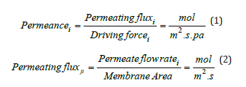
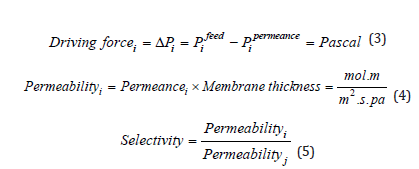
A gas molecule is generally transported across an IILM in three steps: (1) absorption in the ILM’s upstream surface, (2) diffusion across the ILM matrix, and (3) desorption in the ILM’s downstream face. The permeability and selectivity can be found by the following equations [128].
Conclusion and Future Recommendations
This paper examines the complete mechanism, usage, benefits, and drawbacks of conventional technologies used for CO2 capture. Conventional methods have issues with solvent loss, corrosive nature of the solvents, toxicity of solvents, and high energy usage in solvent regeneration. ILs play a critical role in CO2 capture processes [129-134]. The unique features of ILs lead them to a wide range of applications. For CO2 separation, a variety of SILMs, including supported ionic liquid polymer membranes has been thoroughly investigated. The CO2/N2 permeability and selectivity of various ionic liquids with polymer membranes are investigated comprehensively. The CO2/N2 permeability and selectivity is substantially improved by choosing the appropriate size of porous support. Similarly, choosing the suitable membrane support, resulting in superior membrane performance at low and high gas pressures. The testing methods for SILMs must be improved significantly before commercialization.
References
- Kweku D, Bismark O, Maxwell A, Desmond KA, Danso KB, et al. (2018) Greenhouse effect: greenhouse gases and their impact on global warming. Journal of Scientific Research and Reports 17(6): 1-9.
- O Neill S (2020) Global CO2 emissions level off in 2019, with a drop predicted in 2020. Engineering 6(9): 958-959.
- IPCC (2007) Intergovernmental panel on climate change 2007: Impacts, adaptation and vulnerability.
- Mazari SA, Hossain N, Basirun WJ, Mubarak NM, Abro R, et al. (2021) An overview of catalytic conversion of CO2 into fuels and chemicals using metal organic frameworks. Process Safety and Environmental Protection 149: 67-92.
- Huynh HL, Tucho WM, Yu X, Yu Z (2020) Synthetic natural gas production from CO2 and renewable H2: Towards large-scale production of Ni-Fe alloy catalysts for commercialization. Journal of Cleaner Production 264.
- Zhu Y, Chen M, Yang Q, Alshwaikh MJM, Zhou H, et al. (2021) Life cycle water consumption for oxyfuel combustion power generation with carbon capture and storage. Journal of Cleaner Production 281.
- Zarei F, Rahimi MR, Razavi R, Baghban A (2019) Insight into the experimental and modeling study of process intensification for post-combustion CO2 capture by rotating packed bed. Journal of Cleaner Production 211: 953-961.
- Velasco JA, Lopez L, Velásquez M, Boutonnet M, Cabrera S, et al. (2010) Gas to liquids: A technology for natural gas industrialization in Bolivia. Journal of Natural Gas Science and Engineering 2(5): 222-228.
- Wang Y, Zhao L, Otto A, Robinius M, Stolten D (2017) A review of post-combustion CO2 capture technologies from coal-fired power plants. Energy Procedia 114: 50-665.
- Yang H, Xu Z, Fan M, Gupta R, Rachid SB, et al. (2008) Progress in carbon dioxide separation and capture: A review. Journal of Environmental Sciences 20(1): 14-27.
- Mazari SA, Abro R, Bhutto AW, Saeed IM, Ali BS, et al. (2020) Thermal degradation kinetics of morpholine for carbon dioxide capture. Journal of Environmental Chemical Engineering 8(3).
- Saeed IM, Alaba P, Mazari SA, Basirun WJ, Lee VS, et al. (2018) Opportunities and challenges in the development of monoethanolamine and its blends for post-combustion CO2 International Journal of Greenhouse Gas Control 79: 212-233.
- Mazari SA, Ghalib L, Sattar A, Bozdar M, Qayoom A, et al. (2020) Review of modelling and simulation strategies for evaluating corrosive behavior of aqueous amine systems for CO2 International Journal of Greenhouse Gas Control 96.
- Ghalib L, Abdulkareem A, Ali BS, Mazari SA (2020) Modeling the rate of corrosion of carbon steel using activated diethanolamine solutions for CO2 Chinese Journal of Chemical Engineering 288(8): 2099-2110.
- Mazari SA, Alaba P, Saeed IM (2019) Formation and elimination of nitrosamines and nitramines in freshwaters involved in post-combustion carbon capture process. Journal of Environmental Chemical Engineering 7(3).
- (2016) European Environment Agency.
- Dave Jones DAS, Buck M, Graichen P (2018) Sandbag_European-Power-Sector-2018.
- Peters J (2020) Trends in global CO2 and total greenhouse gas emissions.
- Friedlingstein P, Jones MW, Sullivan MO, Andrew RM, Hauck J, et al. (2019) Global carbon budget 2019. Earth System Science Data 11(4): 1783-1838.
- Peters GP, Canadell JG, Andrew RM, Friedlingstein P, Jackson RB (2019) Carbon dioxide emissions continue to grow amidst slowly emerging climate policies. Nature Climate Change 10: 3-6.
- P N E A Agency (2020) Trends in Global CO2 and Total Greenhouse Gas Emissions.
- I E Agency (2021) Global energy-related CO2 emissions, 1990-2020.
- E C P I C Policy (2020) International Ambition on Targets for the Post-2020 Era.
- I E Agency (2021) CO2 emissions from fuel combustion in selected economies, 2000-2019.
- Blomena E, Neele F, Hendriks C (2009) Capture technologies: Improvements and promising developments. Energy Procedia 1(1): 1505-1512.
- Lopez R, Diaz MJ, Gonzalez-Perez JA (2018) Extra CO2 sequestration following reutilization of biomass ash. Sci Total Environ 625: 1013-1020.
- Wall TF (2007) Combustion processes for carbon capture. Proceedings of the Combustion Institute 31(1): 31-47.
- CO2 capture Pathways. Canada.
- Olajire AA (2010) CO2 capture and separation technologies for end-of-pipe applications – A review. Energy 35(6): 2610-2628.
- Visser E, Hendriks C, Barrio M, Mølnvik MJ, Koeijer G, et al. (2008) Dynamis CO2 quality recommendations. International Journal of Greenhouse Gas Control 2(4): 478-484.
- Elwell LCG (2006) Technology options for capturing CO2. US Department of Energy, Office of Scientific and Technical Information.
- (2030) National Energy Information Center, Washington, DC 20585, Annual Energy Outlook 2008, With Projections to 2030.
- Kanniche M, Bonnivard RG, Jaud P, Marcos JV, Amann JM (2010) Pre-combustion, post-combustion and oxy-combustion in thermal power plant for CO2 Applied Thermal Engineering 30(1): 53-62.
- Metz B, Davidson O, Coninck D, Loos M, Meyer LA, et al. (Eds.), (2005) IPCC special report on carbon dioxide capture and storage. Cambridge University Press, New York, Working Group III of the Intergovernmental Panel on Climate Change, USA.
- Lueking AD, Cole MW (2017) Energy and mass balances related to climate change and remediation. Sci Total Environ 590(591): 416-429.
- Alonso A, Vico JM, Markeb AA, Komilis D, Puntes V, et al. (2017) Critical review of existing nanomaterial adsorbents to capture carbon dioxide and methane. Sci Total Environ 595: 51-62.
- Zhang Z, Zeng Q, Hao R, Yang F, Mao X, et al. (2019) Combustion behavior, emission characteristics of SO2, SO3 and NO, and in situ control of SO2 and NO during the co-combustion of anthracite and dried sawdust sludge. Sci Total Environ 646: 716-726.
- Patricia JMR, Seevam N, Downie MJ, Hopkins P (2009) Transporting the next generation of CO2 for carbon, capture and storage: The impact of impurities on supercritical CO2 7th International Pipeline Conference.
- Wilberforce T, Baroutaji A, Soudan B, Alami AHA, Olabi AG (2019) Outlook of carbon capture technology and challenges. Sci Total Environ 657: 56-72.
- Rubin ES, Mantripragada H, Marks A, Versteeg P, Kitchin J (2012) The outlook for improved carbon capture technology. Progress in Energy and Combustion Science 38(5): 630-671.
- Savile CK, Lalonde JJ (2011) Biotechnology for the acceleration of carbon dioxide capture and sequestration. Curr Opin Biotechnol 22(6): 818-823.
- Fauth DJ, Gray ML, Pennline HW, Krutka HM, Sjostrom S, et al. (2012) Investigation of porous silica supported mixed-amine sorbents for post-combustion CO2 Energy & Fuels 26(4): 2483-2496.
- Scholes CA, Ho MT, Wiley DE, Stevens GW, Kentish SE (2013) Cost competitive membrane-cryogenic post-combustion carbon capture. International Journal of Greenhouse Gas Control 17: 341-348.
- Zhang Z, Yan Y, Zhang L, Chen Y, Ju S (2014) CFD investigation of CO2 capture by methyldiethanolamine and 2-(1-piperazinyl)-ethylamine in membranes: Part B. Effect of membrane properties. Journal of Natural Gas Science and Engineering 19: 311-316.
- Jayakumar A, Gomez A, Mahinpey N (2016) Post-combustion CO2 capture using solid K2CO3: Discovering the carbonation reaction mechanism. Applied Energy 179: 531-543.
- Wang M, Yao L, Wang J, Zhang Z, Qiao W, et al. (2016) Adsorption and regeneration study of polyethylenimine-impregnated millimeter-sized mesoporous carbon spheres for post-combustion CO2 Applied Energy 168: 282-290.
- Nwaoha C, Supap T, Idem R, Saiwan C, Tontiwachwuthikul P, et al. (2017) Advancement and new perspectives of using formulated reactive amine blends for post-combustion carbon dioxide (CO2) capture technologies. Petroleum 3(1): 10-36.
- Vellini M, Gambini M (2015) CO2 capture in advanced power plants fed by coal and equipped with OTM. International Journal of Greenhouse Gas Control 36: 144-152.
- Smith RF, Zeng P, Ahn J (2017) Investigation of oxygen transport membrane reactors for oxy-fuel combustion and carbon capture purposes. Proceedings of the Combustion Institute 36(3): 3969-3976.
- Song C, Liu Q, Deng S, Li H, Kitamura Y (2019) Cryogenic-based CO2 capture technologies: State-of-the-art developments and current challenges. Renewable and Sustainable Energy Reviews 101: 265-278.
- Leung DYC, Caramanna G, Valer MMM (2014) An overview of current status of carbon dioxide capture and storage technologies. Renewable and Sustainable Energy Reviews 39: 426-443.
- Dai Z, Ansaloni L, Deng L (2016) Recent advances in multi-layer composite polymeric membranes for CO2 separation: A review. Green Energy & Environment 1(2): 102-128.
- Nandi PDLS, Daff TD, Rother J, Liu M, Buchanan W, et al. (2015) A single-ligand ultra-microporous MOF for precombustion CO2 capture and hydrogen purification. Sci Adv 1(11).
- Hedin N, Andersson L, Bergström L, Yan J (2013) Adsorbents for the post-combustion capture of CO2 using rapid temperature swing or vacuum swing adsorption. Applied Energy 104: 418-433.
- Tonziello J, Vellini M (2011) Oxygen production technologies for IGCC power plants with CO2 Energy Procedia 4: 637-644.
- D'Alessandro DM, Smit B, Long JR (2010) Carbon dioxide capture: Prospects for new materials. Angew Chem Int Ed Engl 49(35): 6058-6082.
- Ramdin M, Loos TWD, Vlugt TJH (2012) State-of-the-Art of CO2 Capture with Ionic Liquids. Industrial & Engineering Chemistry Research 51(24): 8149-8177.
- Porter RTJ, Fairweather M, Pourkashanian M, Woolley RM (2015) The range and level of impurities in CO2 streams from different carbon capture sources. International Journal of Greenhouse Gas Control 36: 161-174.
- Kather A, Kownatzki S (2011) Assessment of the different parameters affecting the CO2 purity from coal fired oxyfuel process. International Journal of Greenhouse Gas Control 5(1): S204-S209.
- Martynov SB, Daud NK, Mahgerefteh H, Brown S, Porter RTJ (2016) Impact of stream impurities on compressor power requirements for CO2 pipeline transportation. International Journal of Greenhouse Gas Control 54(2): 652-661.
- White CM, Strazisar BR, Granite EJ, Hoffman JS, Pennline HW, et al. (2003) Separation and capture of CO2 from large stationary sources and sequestration in geological formations--coalbeds and deep saline aquifers. J Air Waste Manag Assoc 53(6): 645-715.
- Rubin ABRAES (2003) A technical, economic, and environmental assessment of amine-based CO2 capture technology for power plant greenhouse gas control. American Chemical Society, US.
- Brunetti A, Scura F, Barbieri G, Drioli E (2010) Membrane technologies for CO2 Journal of Membrane Science 359(1-2): 115-125.
- (2007) Carbon dioxide capture from existing coal-fired power plants. National Energy Technology Laboratory, US.
- Zhang C, Zhang W, Gao H, Bai Y, Sun Y, et al. (2017) Synthesis and gas transport properties of poly (ionic liquid) based semi-interpenetrating polymer network membranes for CO2/N2 J Membr Sci 528: 72-81.
- Samanta A, Zhao A, Shimizu GKH, Sarkar P, Gupta R (2011) Post-combustion CO2 capture using solid sorbents: A Review. Industrial & Engineering Chemistry Research 51(4): 1438-1463.
- Thiruvenkatachari R, Su S, An H, Yu XX (2009) Post combustion CO2 capture by carbon fibre monolithic adsorbents. Progress in Energy and Combustion Science 35(5): 438-455.
- Yancheshmeh MS, Radfarnia HR, Iliuta MC (2016) High temperature CO2 sorbents and their application for hydrogen production by sorption enhanced steam reforming process. Chemical Engineering Journal 283: 420-444.
- Ebner MLGAD, Chisholm NG, Black QT, Mumford DD, Nicholson MA, et al. (2011) Suitability of a solid amine sorbent for CO2 capture by pressure swing adsorption. American Chemical Society.
- Bamdad H, Hawboldt K, MacQuarrie S (2018) A review on common adsorbents for acid gases removal: Focus on biochar. Renewable and Sustainable Energy Reviews 81(2): 1705-1720.
- Richter HJ, Knoche KF (1983) Reversibility of combustion processes, in efficiency and costing. ACS Symposium Series, pp. 71-85.
- Erans M, Manovic V, Anthony EJ (2016) Calcium looping sorbents for CO2 Applied Energy 180: 722-742.
- Luo M, Yi Y, Wang S, Wang Z, Du M, et al. (2018) Review of hydrogen production using chemical-looping technology. Renewable and Sustainable Energy Reviews 81: 3186-3214.
- Adanez J, Abad A, Labiano FG, Gayan P, Diego LFD (2012) Progress in chemical-looping combustion and reforming technologies. Progress in Energy and Combustion Science 38(2): 215-282.
- Solunke RD, Veser G (2011) Integrating desulfurization with CO2-capture in chemical-looping combustion. Fuel 90(2): 608-617.
- Abuelgasim S, Wang W, Abdalazeez A (2021) A brief review for chemical looping combustion as a promising CO2 capture technology: Fundamentals and progress. Sci Total Environ 764: 142892.
- Holmes AS, Ryan JM (1982) Cryogenc distillative separation of acid gases from methane. United States Patent.
- Li G, Bai P (2012) New operation strategy for separation of ethanol-water by extractive distillation. Industrial & Engineering Chemistry Research 51(6): 2723-2729.
- Ebrahimzadeh E, Matagi J, Fazlollahi F, Baxter LL (2016) Alternative extractive distillation system for CO2–ethane azeotrope separation in enhanced oil recovery processes. Applied Thermal Engineering 96: 39-47.
- Kazemi A, Hosseini M, Zeinabad AM, Faizi V (2016) Evaluation of different vapor recompression distillation configurations based on energy requirements and associated costs. Applied Thermal Engineering 94: 305-313.
- Jana AK (2016) A new divided-wall heat integrated distillation column (HIDiC) for batch processing: Feasibility and analysis. Applied Energy 172: 199-206.
- Maqsood K, Mullick A, Ali A, Kargupta K, Ganguly S (2014) Cryogenic carbon dioxide separation from natural gas: a review based on conventional and novel emerging technologies. J Reviews in Chemical Engineering 30(5): 453-477.
- Khuram M, Azmi BM, Saibal G, Ali A (2014) Synthesis of conventional and hybrid cryogenic distillation sequence for purification of natural gas. Journal of Membrane Sciences.
- Maqsood K, Pal J, Turunawarasu D, Pal AJ, Ganguly S (2014) Performance enhancement and energy reduction using hybrid cryogenic distillation networks for purification of natural gas with high CO2 Korean Journal of Chemical Engineering 31(7): 1120-1135.
- Maqsood K, Ali A, Nasir R, Abdulrahman A, Mahfouz AB, et al. (2021) Experimental and simulation study on high-pressure V-L-S cryogenic hybrid network for CO2 capture from highly sour natural gas. Process Safety and Environmental Protection 150: 36-50.
- Maqsood K, Ali A, Shariff ABM, Ganguly S (2017) Process intensification using mixed sequential and integrated hybrid cryogenic distillation network for purification of high CO2 natural gas. Chemical Engineering Research and Design 117: 414-438.
- Zhong DL, Sun DJ, Lu YY, Yan J, Wang JL (2014) Adsorption–hydrate hybrid process for methane separation from a CH4/N2/O2 gas mixture using pulverized coal particles. Industrial & Engineering Chemistry Research 53(40): 15738-15746.
- Babu P, Linga P, Kumar R, Englezos P (2015) A review of the hydrate based gas separation (HBGS) process for carbon dioxide pre-combustion capture. Energy 85: 261-279.
- Lee HJ, Lee JD, Linga P, Englezos P, Kim YS (2010) Gas hydrate formation process for pre-combustion capture of carbon dioxide. Energy 35(6): 2729-2733.
- Kumar R, Wu HJ, Englezos P (2006) Incipient hydrate phase equilibrium for gas mixtures containing hydrogen, carbon dioxide and propane. Fluid Phase Equilibria 244(2): 167-171.
- Tang J, Zeng D, Wang C, Chen Y, He L, et al. (2013) Study on the influence of SDS and THF on hydrate-based gas separation performance. Chemical Engineering Research and Design 91(9): 1777-1782.
- Mondal MK, Balsora HK, Varshney P (2012) Progress and trends in CO2 capture/separation technologies: A review. Energy 46(1): 431-441.
- Khalilpour R, Mumford K, Zhai H, Abbas A, Stevens G, et al. (2015) Membrane-based carbon capture from flue gas: a review. Journal of Cleaner Production 103: 286-300.
- Hussain A, Hägg MB (2010) A feasibility study of CO2 capture from flue gas by a facilitated transport membrane. Journal of Membrane Science 359(1-2): 140-148.
- Berstad D, Anantharaman R, Nekså P (2013) Low-temperature CCS from an IGCC power plant and comparison with physical solvents. Energy Procedia 37: 2204-2211.
- Sifat NS, Haseli Y (2019) A critical review of CO2 capture technologies and prospects for clean power generation. Energies 12(21).
- Zhang Z, Borhani T, El-Naas M (2018) Carbon capture, exergetic, energetic and environmental dimensions. Elsevier, Netherlands.
- Jansen D, Gazzani M, Manzolini G, Dijk E, Carbo M (2015) Pre-combustion CO2 International Journal of Greenhouse Gas Control 40: 167-187.
- Stanger R, Wall T, Spörl R, Paneru M, Grathwohl S, et al. (2015) Oxyfuel combustion for CO2 capture in power plants. International Journal of Greenhouse Gas Control 40: 55-125.
- Theo WL, Lim JS, Hashim H, Mustaffa AA, Ho WS (2016) Review of pre-combustion capture and ionic liquid in carbon capture and storage. Applied Energy 183: 1633-1663.
- Merkel TC, Lin H, Wei X, Baker R (2010) Power plant post-combustion carbon dioxide capture: An opportunity for membranes. Journal of Membrane Science 359(1-2): 126-139.
- Xu G, Liang F, Yang Y, Hu Y, Zhang K, et al. (2014) An improved CO2 separation and purification system based on cryogenic separation and distillation theory. Energies 7(5): 3484-3502.
- Song C, Liu Q, Ji N, Deng S, Zhao J, et al. (2018) Alternative pathways for efficient CO2 capture by hybrid processes-A review. Renewable and Sustainable Energy Reviews 82: 215-231.
- Eslamimanesh A, Mohammadi AH, Richon D, Naidoo P, Ramjugernath D (2012) Application of gas hydrate formation in separation processes: A review of experimental studies. The Journal of Chemical Thermodynamics 46: 62-71.
- Castel C, Favre E (2018) Membrane separations and energy efficiency. Journal of Membrane Science 548: 345-357.
- Buonomenna MG, Bae J (2015) Membrane processes and renewable energies. Renewable and Sustainable Energy Reviews 43: 1343-1398.
- Cheng X, Pan F, Wang M, Li W, Song Y, et al. (2017) Hybrid membranes for pervaporation separations. Journal of Membrane Science 541: 329-346.
- Jordan A, Gathergood N (2015) Biodegradation of ionic liquids--a critical review. Chem Soc Rev 44(22): 8200-8237.
- Meseret Made JFL, Pang L (2015) Environmental application, fate, effects and concerns of ionic liquids: A review. Environmental Science & Technology.
- Jadhav VH, Kim JG, Park SH, Kim DW (2017) Task-specific hexaethylene glycol bridged di-cationic ionic liquids as catalysts for nucleophilic fluorination using potassium fluoride. Chemical Engineering Journal 308: 664-668.
- Patil SK, Patil SA, Vadiyar MM, Awale DV, Sartape AS, et al. (2017) Tailor-made dicationic ionic liquid as a fluorescent sensor for detection of hydroquinone and catechol. Journal of Molecular Liquids 244: 39-45.
- Singh SK, Savoy AW (2020) Ionic liquids synthesis and applications: An overview. Journal of Molecular Liquids 297.
- Aghaie M, Rezaei N, Zendehboudi S (2018) A systematic review on CO2 capture with ionic liquids: Current status and future prospects. Renewable and Sustainable Energy Reviews 96: 502-525.
- Torralba-Calleja E, Skinner J, Gutiérrez-Tauste D (2013) CO2 capture in ionic liquids: A review of solubilities and experimental methods. Journal of Chemistry pp. 1-16.
- Shannon MS, Bara JE (2011) Properties of alkylimidazoles as solvents for CO2 capture and comparisons to imidazolium-based ionic liquids. Industrial & Engineering Chemistry Research 50(14): 8665-8677.
- Rosli A, Ahmad AL, Jit Kiang L, Siew Chun L (2017) Advances in liquid absorbents for CO2 capture: A review. Journal of Physical Science 28(1): 121-144.
- Lyddon BBL (2008) A-comparison-of-physical-solvents-for-acid-gas-removal. Gas Processors Association Convention, Grapevine Bryan, Texas, USA.
- Zhang X, Zhang X, Dong H, Zhao Z, Zhang S, et al. (2012) Carbon capture with ionic liquids: overview and progress. Energy & Environmental Science 5(5): 6668-6681.
- Xie Y, Zhang Y, Lu X, Ji X (2014) Energy consumption analysis for CO2 separation using imidazolium-based ionic liquids. Applied Energy 136: 325-335.
- Wang J, Luo J, Feng S, Li H, Wan Y, et al. (2016) Recent development of ionic liquid membranes. Green Energy & Environment 1(1): 43-61.
- Matsumoto M, Panigrahi A, Murakami Y, Kondo K (2011) Effect of ammonium-and phosphonium-based ionic liquids on the separation of lactic acid by supported ionic liquid membranes (SILMs). Membranes (Basel) 1(2): 98-108.
- Miyako E, Kamiya N, Goto M, Maruyama T (2003) Use of ionic liquids in a lipase-facilitated supported liquid membrane. Biotechnol Lett 25(10): 805-808.
- Matsumoto M, Inomoto Y, Kondo K (2005) Selective separation of aromatic hydrocarbons through supported liquid membranes based on ionic liquids. Journal of Membrane Science 246(1): 77-81.
- Ríos AP, Hernández-Fernández FJ, Tomás-Alonso F, Palacios JM, Gómez D, et al. (2007) A SEM–EDX study of highly stable supported liquid membranes based on ionic liquids. Journal of Membrane Science 300(1-2): 88-94.
- Yan X, Anguille S, Bendahan M, Moulin P (2019) Ionic liquids combined with membrane separation processes: A review. Separation and Purification Technology 222: 230-253.
- Dai Z, Noble RD, Gin DL, Zhang X, Deng L (2016) Combination of ionic liquids with membrane technology: A new approach for CO2 Journal of Membrane Science 497: 1-20.
- Meshksar M, Sedghamiz MA, Zafarnak S, Rahimpour MR (2020) CO2 separation with ionic liquid membranes. Advances in Carbon Capture pp. 291-309.
- Galiano F, Mancuso R, Guazzelli L, Mauri M, Chiappe C, et al. (2021) Phosphonium ionic liquid-polyacrylate copolymer membranes for improved CO2 Journal of Membrane Science 635.
- Gu SH, Nicolas V, Lalis A, Sathirapongsasuti N, Yanagihara R (2013) Complete genome sequence and molecular phylogeny of a newfound hantavirus harbored by the Doucet's musk shrew (Crocidura douceti) in Guinea. Infect Genet Evol 20: 118-123.
- Lu SC, Khan AL, Vankelecom IFJ (2016) Polysulfone-ionic liquid based membranes for CO2/N2 separation with tunable porous surface features. Journal of Membrane Science 518: 10-20.
- Cserjési P, Nemestóthy N, Bélafi-Bakó K (2010) Gas separation properties of supported liquid membranes prepared with unconventional ionic liquids. Journal of Membrane Science 349(1-2): 6-11.
- Bara JE, Gabriel CJ, Carlisle TK, Camper DE, Finotello A, et al. (2009) Gas separations in fluoroalkyl-functionalized room-temperature ionic liquids using supported liquid membranes. Chemical Engineering Journal 147(1): 43-50.
- Deligöz H, Yılmazoğlu M (2011) Development of a new highly conductive and thermo mechanically stable complex membrane based on sulfonated polyimide/ionic liquid for high temperature anhydrous fuel cells. Journal of Power Sources 196(7): 3496-3502.
- Huang K, Zhang XM, Li YX, Wu YT, Hu XB (2014) Facilitated separation of CO2 and SO2 through supported liquid membranes using carboxylate-based ionic liquids. Journal of Membrane Science 471: 227-236.
© 2023 Waqad Ul Mulk. This is an open access article distributed under the terms of the Creative Commons Attribution License , which permits unrestricted use, distribution, and build upon your work non-commercially.
Editor In Chief


.jpg)


Signup for Newsletter

Quick Links
 Editorial Board Registrations
 Submit your Article
 Refer a Friend
 Advertise With Us
Our Recent Edition

.jpg)


Top Editors


.jpg)


.bmp)
.jpg)
.png)
.jpg)


.jpg)


.png)

.png)


.png)


Financial Support

Sponsors

Latest e-Books

Latest Video

 a Creative Commons Attribution 4.0 International License. Based on a work at www.crimsonpublishers.com.
Best viewed in
a Creative Commons Attribution 4.0 International License. Based on a work at www.crimsonpublishers.com.
Best viewed in