- Submissions

Full Text
Aspects in Mining & Mineral Science
Stability Analysis of Soldier-Piled Walls with Tied-Background Anchored
Rajesh Rai1*, Ashok Jasiwal1, B K Shrivastva1, Deepak Dagdi2 and Ajit Jha2
1Department of Mining Engineering, Indian Institute of Technology, Banaras Hindi Univeristy, India
2Indigo Infraprojects Pvt Ltd., India
*Corresponding author: Rajesh Rai, Department of Mining Engineering, Indian Institute of Technology (Banaras Hindi Univeristy), Varanasi, UP, India
Submission: January 16, 2021;Published: October 07, 2021

ISSN 2578-0255Volume7 Issue4
Abstract
The present paper analyses the variation of soldier pile and tied background anchored for a case study. The displacement and bending movement have been calculated by limit equilibrium and numerical modelling method. The maximum depth of excavation was 16.3m. The upper strata of this area comprise the alluvium, made up predominantly of sandy silt and silty sand with gravel. Various retaining systems of combination of soldier piles and temporary ground anchors with waler beam and timber lagging have been considered for analysis purpose. Anchor force has been calculated based on limit equilibrium and numerical modeling. Three levels of anchors have been installed with different pretension load. Anchors have been designed with max. load of 600kN with 2 loops of 15.2mm strands with 9m bond length.
Keywords: Soldier pile; Numerical modeling; Ground anchored; Bending; Shear movement
Introduction
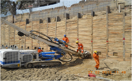
Soldier beam and lagging walls are the very commonly used in design and support of anchored wall system. Wall deformation could be minimized by using Soldier-pile with horizontal timber lags in vertical excavations. It is mainly use in stiff soil conditions where water infiltration into the excavated area is less or negligible. It having less costly and easily installed om the excavation site [1]. Generally, in the construction projects the retaining walls are used as temporary structures. The large wall deformations can be acceptable until it prevents the failure of wall or excavation. The stability of a wall of the excavation area is very important. However, if any excess ground settlement occurs behind the wall it can also leads to serious damage to nearby buildings [1,2]. Therefore, both stability and settlement is important during design of soldier pile around the excavations. Soldier pile and lagging walls are constructed by driving/drilling piles through the proposed excavation depth, and lagging is placed in between the piles as the soil is excavated in stages downward. Figure 1 shows Soldier pile with timber lagging and installation of ground anchored [3,4]. The present discussed the design the soldier pile system. Soil nails has been used for reinforcing the excavation system along with solider pile. The problem is simulated by limit equilibrium method and finite element method with the help of modelling software namely Geo5 and PHASE2 respectively. The parameters have been optimized and a design is predicted within the prescribed factor of safety.
Figure 1: Soldier pile with timber lagging and installation of ground anchored.
Simulation of Earth Retaining System
The upper strata of this area comprise the alluvium, made up predominantly of sandy silt and silty sand with gravel. These alluviums are underlain by harder formations of the system of rocks. The maximum excavation depths of the pit are 14.3m and 9.6m adjacent to the pile wall. Bending moment, shear forces and displacement on the soldier piles during and after complete excavation have been calculated. Temporary earth retaining system with combination of soldier piles, ground anchors with waler beam and timber lagging have been considered for analysis purpose. In present paper only one section has been simulated and discussed. Geo5 software based on Limit equilibrium method has been used. Phase2 software based on Finite element method has been used to simulate the soldier pile with ground anchors. A typical discretized view of the base model is shown in Figure 2. The Model is discretized in triangular shaped elements and joint interface is used to take into account the behavior different material. The Mohr– coulomb elastic-perfectly plastic model has been considered. The depth of proposed excavation is 14.3m from the surface and soldier piles have been installed upto depth of 19.0m (i.e. about 1.33 times of the excavation) and 13m (i.e. about 1.35 times of the excavation) before the excavation. Number of models have been prepared and simulated by considering various permutation and combination of different size of girder, anchors capacity and spacing. Three layers of anchors at 3.5m, 8.2m and 11.5 from the surface have been installed in the sequential stage of excavation. The inclination of anchors has been considered 200 from horizontal. The typical sequential stages of excavation have been shown in Figure 2. Table 1 show the properties used in the simulation of excavation. Tables 2 & 3 show the properties of anchor reinforcement and structural respectively.
Figure 2: Discretized model of excavation by finite element method.
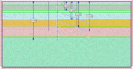
Table 1: Soil parameters used in the simulation.

Table 2: Anchor properties used in the simulation.

Table 3: Structural properties used in the simulation.

Result and Discussion
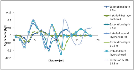
Figure 3 shows the simulation results of last stage when maximum excavation has been completed and anchors have been installed. It shows displacement of structure, bending moment, shear force and pressure on structure with maximum value. The maximum bending moment is 158.80kNm/m in the last stage. The maximum axial forces anchors are 599.56kN in anchor no 3 at last stage. Figure 3 shows the simulation results of last stage when maximum excavation has been completed and anchors have been installed. It shows displacement of structure, bending moment, shear force and pressure on structure with maximum value. The maximum bending moment is 158.80kNm/m in the last stage. The maximum axial forces anchors are 599.56kN in anchor no 3 at last stage (Figures 4-6).
Figure 3: Discretized model of excavation by finite element method.
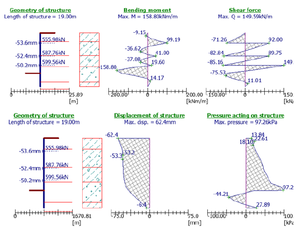
Figure 4: Horizontal displacement in different at last stages.
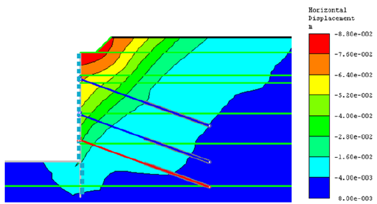
Figure 5: Bending moments in structure element at various excavation stages.
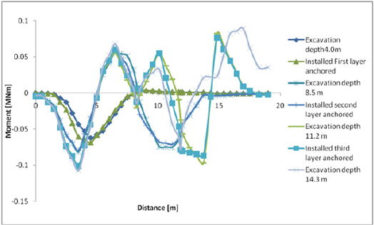
Figure 6: Shear forces in structure element at various excavation stages.
Design for Anchor Force
The design of anchored is based on maximum working load which is estimated by limit equilibrium and finite element modeling. The maximum working load on anchor is around 600kN. Seven wire high tensile steel strand (IS: 14268-1995) with diameter of 15.2 has been used. The ultimate strength of wire is 270kN is taken.
Number of strand loops required:
Strand Ultimate Tensile strength=270kN
Loop ultimate tensile strength=2x270=540kN
N (No. loops)=(Working Load X FOS for Strands)/Ultimate
Strength of Loop
Number of strands for: 600kN Ton Anchor=(600 X
1.6)/540=1.77~2 Loops
Bond length calculations:
Drill Hole Diameter=165mm
Skin Friction for silty sand: 260N/mm2
Bond Length=(Working Load X FOS for bond)/(Skin Friction x
Bond Area)
= (600 x 2)/260 x 3.14 x .165=8.91m
Bond Length=8.91m~9.0m
Conclusion
The shoring system has been analysed with GEO5 and
Phases2 and results obtained for bending moment, shear forces,
displacement and axial forces have been calculated and are under
safe limits. The following conclusions have been drawn based on
simulation of shoring system:
a. Solder piles of ISMB 450mm has to be installed upto depth
of solder pile is 19m for excavation depth of the pit is 16.3m below
EGL & 14.3M adjacent to the pile wall.
b. Soldier piles shall be bored and inserted at 1.6m (centre
to centre) spacing.
c. Anchors were designed with max. load of 600kN with
2 loops of 15.2mm strands & 9m bond length and free lengths as
shown in drawings.
References
- Lee CJ, Wei YC, Chen HT, Chang YY, Lin YC, et al. (2011) Stability analysis of cantilever double soldier-piled walls in sandy soil. Journal of the Chinese Institute of Engineers 34(4): 449-465.
- Geotechnical Design Manual (2013) Selection of Retaining Wall System Type. Oregon Department of Transportation, pp. 15-23.
- Lunne T, Robertson PK, Powell JJM (1997) Cone penetrating testing in geotechnical practice. Taylor & Francis, CRC Press, London, United Kingdom.
- Trenching and Shoring Manual (2000) Earth pressure theory and applications. Department of Transportation, State of California, USA, pp. 4-1.
© 2021 Rajesh Rai. This is an open access article distributed under the terms of the Creative Commons Attribution License , which permits unrestricted use, distribution, and build upon your work non-commercially.
 a Creative Commons Attribution 4.0 International License. Based on a work at www.crimsonpublishers.com.
Best viewed in


.jpg)


 Editorial Board Registrations
 Submit your Article
 Refer a Friend
 Advertise With Us
.jpg)


.jpg)


.bmp)
.jpg)
.png)
.jpg)


.jpg)


.png)

.png)


.png)


