- Submissions

Full Text
Aspects in Mining & Mineral Science
Innovative Engineering Design of the High-Angle Conveyor for Mining of Deep-Seated Mineral Deposits
Glebov Andrey Valerjevich*, Karmaev Gennadiy Dmitrijevich and Bersenev Viktor Anatoljevich
Candidate of Engineering Sciences, Federal State Budget Establishment the Institute of Mining, Russia
*Corresponding author: Glebov Andrey Valerjevich, Candidate of Engineering Sciences, Deputy Director on Scientific Questions, Federal State Budget Establishment the Institute of Mining, Ural Branch Russian Academy of Sciences (IM UB RAS), Russia
Submission: June 01, 2018;Published: September 12, 2018

ISSN 2578-0255Volume2 Issue2
Annotation
The article analyzes the engineering design and the process of transportation of coarse-grained rock mass by two-contour steep-inclined conveyors with stationary clamping devices, shows their most significant disadvantages. It shows the structure of the dual steeply inclined conveyor with a moving clamping elements, developed by the staff of the Institute of Mining UB RAS, the design feature of which is the implementation of the clamping elements in the form of corrugations affixed to the outer (working) belt surface of the load carrying profile. Design features of the steep-slope belt conveyor with moving clamping elements in form of corrugations provide a reliable rise of uneven flow of rock mass due to: the simultaneous use of forced pressing of the transported material in the chute of the load-bearing belt and of the effect of deep fluting; clamping elements moving synchronously with the load-bearing belt, resilient-elastic properties of clamping elements, allowing them to perform an additional supporting function for the transported material. Studies have shown that the developed design provides an increase in the coefficient of use of the equipment in 2 times, reducies tape wear by 20-40%, compared with foreign analogues.
It is established that with the annual capacity of the complexes of cyclic-flow technology (CFT) of 5-10 million tonne the steeply inclined conveyors should be used on the hoisting heights of the rock mass more than 100-200m. This reduces unit operating costs by 5-20% and capital costs by 13-30% for complexes of CFT with steeply inclined conveyors. Furthermore, the use of steeply inclined conveyor allows to increase the productivity per worker of CFT complex by 8-20%. With the increased capacity of complexes up to 20-30 million ton per year steeply inclined conveyors should be used for hoisting heights of the rock mass more than 200-300m. Under these conditions, the small difference in unit operating costs (less than 10%), capital costs for complexes of CFT with steeply inclined conveyors are reduced by 10-22%.
Keywords: Dual steeply inclined conveyor; Load carrying belt; Hoisting belt; Mechanical clamping device; Moving clamping elements with resilientelastic properties; Corrugation; Inclination angle; Traditional belt conveyor; The cost of transportation
Introduction
The development of open pit mines is accompanied by an increase in the depth of quarries, changes in mining and geological and mining conditions. Ensuring further increase in production of large quarries depends on the correct choice of flexible technological schemes of development and mining equipment, the most adapted to the internal infrastructure. The use of a steep belt conveyor in these conditions will improve the efficiency of the systems of cyclicflow technology (CFT).
In comparison with traditional conveyors, inclined conveyors are able to move bulk materials at an angle of 50-60° or more. This allows to significantly reduce the amount of mining and capital work in the preparation of the lift route on Board the quarry. The influence of the angle of its slope and the height of the rise of the rock mass can be traced according to the specific capital and operating costs for crushing and conveyor complexes (CCC) with an annual volume of traffic of 20 million tons (Figure 1) [1]. From Figure 1 it can be seen that the difference in costs, especially operating costs, for crushing and conveyor systems with the slope angles of the conveyor lift route 18° and 60° is not very large at the height of the material lifting up to 100-200m. It becomes noticeable when the material rises above 200m.
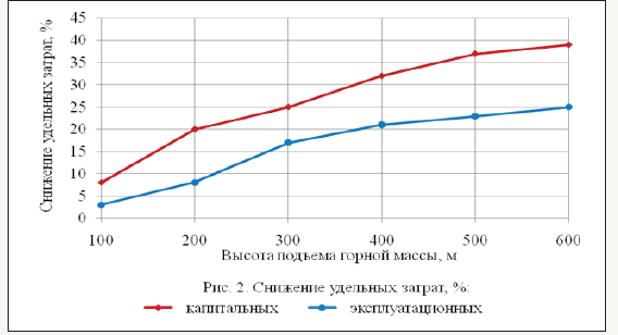
Reduction of costs for the crushing and conveyor complex with a slope angle of the lift route 60° in comparison with the complexes in which the conveyor lift is installed at an angle of 18° is shown in Figure 2. The results show that the use of steeply inclined conveyor lifts are useful to consider when the lifting height of the mountain masses of more than 100-150m. This applies to mining conditions, the use of both traditional and steeply inclined conveyors. In other conditions of quarries, when it is very difficult to place traditional conveyors without large volumes of mining and capital works, the use of steep ones does not raise doubts practically from the depth of transition to combined transport.
Figure 1:Change of specific capital and operating costs for crushing and conveyor complexes depending on the hoisting height of the rock mass and the angle of inclination of the conveyor elevator: inclination angle of the conveyor (β), height of material hoisting (hп), specific capital (Куд) and operating (Эуд) costs.
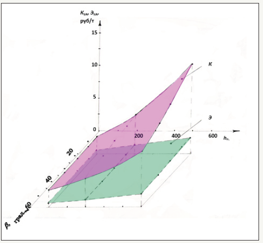
Figure 2:
Current status of the issue
The use of steeply inclined conveyor systems can significantly improve the efficiency of motor and conveyor transport. Domestic and foreign organizations and manufacturers have developed a large number of steeply inclined conveyors for various operating conditions. There are steeply inclined belt conveyors with corrugated belts, providing lifting of cargo at an angle of up to 27°, with transverse partitions and corrugated side walls, with transverse partitions without side boards, belt-bucket type (lifting angle up to 30°), tubular type (lifting angle up to 30-50°). The use of plate conveyors with partitions for the steep lifting of the rock mass from the quarries is considered. It is proposed to use a conveyor belt and chain type with retaining partitions without bottoms. In this case, the conveyor belt is a load-bearing, moves due to the friction forces with the transported material and partitions, which are driven by a traction-driven chain circuit [2].
The experience of operation of continuous-action units with traction chain circuits (plate and scraper conveyors, bucket elevators, etc.) shows that due to the low reliability and durability of chain traction bodies, such designs practically do not meet the requirements for the equipment of career conveyor transport. This fully applies to the conveyor belt and chain type.
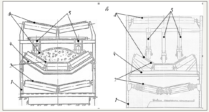
In deep pits for transporting lumpy rock mass preferred dual belt conveyors with a pressure (transshipments) ribbons (tilt angle up to 25-30) and additional pressing gruzoperevalki tapes mechanical devices located stationary in the linear part of the conveyor (elevation angle more than 30°) [3,4]. The design of the linear rate of this type of conveyor is shown in Figure 3. Doublecircuit belt conveyors with mechanical clamping devices of loadholding belts have found quite wide application abroad and are beginning to be implemented in the complexes of the CFT in Russia and CIS countries.
Figure 3:The design of the linear frame of double-circuit belt conveyor with clamping (load-holding) belts: a) with two clamping rollers; b) with three clamping rollers; 1-supporting metal construction; 2-load-carrying contour belt; 3-roller support; 4-loadholding contour belt; 5-clamping elements with rollers.
In Russia, the steeply inclined conveyor with a clamping belt is mounted in Olenegorsky [5,6]. One of the most powerful conveyors is mounted on the quarry of Muruntau of Navoi GOK (Uzbekistan) [7,8]. It is manufactured by Novo-Kramatorsk machine building plant (NKMZ, Ukraine). Less powerful steeply inclined conveyor operated at the mine “Maidanek” (Yugoslavia) until 1996 [9]. Technical characteristics of these conveyors are given in Table 1.
Table 1:Key specifications of high-angle conveyors.

Table 2:Capability of the special high-angle conveyors NKMZ.

The question of application of steeply inclined conveyor lifts with capacity of 3000-3500t/h on Kovdorsky GOK (Russia) (height of lifting of material of 140m) is considered; Central GOK (Ukraine) (height of lifting of material of 175m). The intended manufacturer is NKMZ. In addition to these NKMZ manufactures special steeplyinclined conveyors (Table 2). Other machine-building plants of the CIS countries do not produce powerful steeply inclined conveyors.
Analysis of the embodiment and transportation process of coarse rock mass by two-circuit steeply inclined conveyors with stationary clamping devices revealed their significant drawbacks:
A. Permanently installed clamping devices of the loadcarrying belt create the preconditions for the movement of the transported material between them in the direction of the tail of the conveyor with uneven loading of the belt. This phenomenon reduces the reliability and safety of the conveyor;
B. Dynamic loads arising during the interaction of clamping devices with pieces of transported material significantly increase its movement, which significantly increases the wear of the working surfaces of conveyor belts;
C. Reduction of the receiving capacity of the load-carrying tape to 15-20% due to the use of its side bands with a width of about 200-250mm for pressing the load-carrying tape with side rollers.
D. These disadvantages can be eliminated by using clamping elements that have the ability to move together with the transported material and pressing the load regardless of the height of its location in the chute of the load-bearing belt.
Research Result
As a result of the analysis of the structures of steeply inclined conveyors by the employees of IGD Uro RAS, a schematic diagram of a two-circuit steeply inclined conveyor with moving clamping elements was developed [10]. A feature of the design is the performance of clamping elements in the form of corrugations fixed to the outer (working) surface of the belt of the load-holding circuit. Corrugations are made of resilient-elastic material, have good damping ability and restore their shape after the disappearance of contact with the transported material. The maximum height of the corrugation corresponds to the depth of the gutter of the loadbearing tape, and in the absence of rock mass on it, the corrugation enters its gutter and performs the function of a partition.
To increase the holding effect, it is advisable to increase the area of contact of the corrugation with the transported material. This can be achieved by flattenings the surface of a rock mass in the chute load-carrying belt. Modeling in laboratory conditions was tested the method of levelings of rock mass by increasing the angle of inclination of the side rollers in frame linear of conveyor after a section of the load. Experimental studies of the state of the load during the movement of the load-bearing belt found that the increase in the angle of inclination of the side rollers gives positive results of the formation of a flat (horizontal) surface of a coarse rock mass in the trough of the tape.
The performed calculations showed that, with a width of the load-bearing belt of 1,4m, the installation of side rollers in the roller supports of the loading point at an angle of 30° and the angle of slope of the transported material in the chute of the load-bearing belt 15° the maximum angle of installation of the side rollers in the 48°.
In addition to increasing the contact surface of the clamping elements in the form of corrugation with the transported material, the installation of a linear footing roller carriage with a large angle of inclination of the side roller carriage the friction force of the rock mass with the load-bearing belt due to the effect of deep grooving.
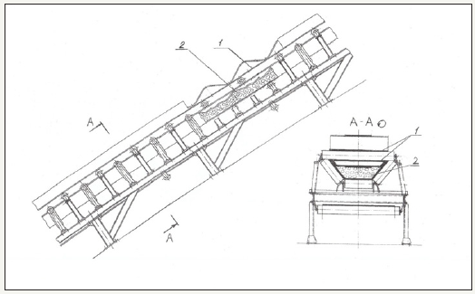
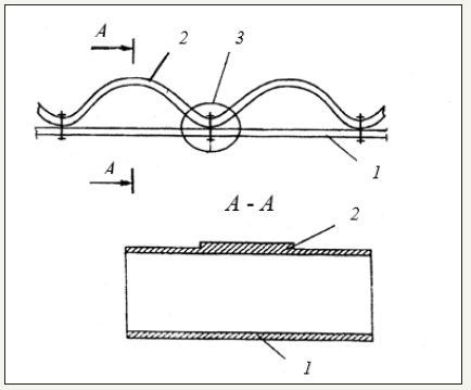
The design features of the steeply inclined belt conveyor with moving clamping elements in the form of corrugation provide a reliable rise of uneven flow of rock mass due to: the joint use of forced pressing of the transported material in the chute of the load-bearing tape and the effect of deep groove; synchronous with the load-bearing belt movement of clamping elements; elastic properties of clamping elements, allowing them to perform the additional function of backing the transported material. The section of the linear rate and its cross section are shown in Figure 4, and the principal execution of the belt load-holding circuit-in Figure 4.
Figure 4:The linear frame of high-angle conveyor (design of the Institute of Mining UB RAS) 1-load-holding belt with corrugations; 2-transported material.
Based on the principles of safe holding large lump rock mass in the load-carrying belt chute steeply inclined conveyor with a moving clamping elements, Mining Institute UB RAS:
A. The main provisions of calculation of its main parameters are developed;
B. The interaction of clamping elements (corrugation) with the transported material is investigated and the dependences of the change in clamping force on their main parameters (height and thickness of the cross section) at different conveyor performance are established;
C. The distance between adjacent corrugations based on the theory of stability of the rods, determined by the balance of forces, rolling the load in the direction of the tail of the conveyor, and the friction forces between the rock mass and compressing its surfaces of the corrugation and the load-bearing belt is justified;
D. The economic and mathematical model of calculation of parameters of steep conveyors of this type and the cost of transportation of rock mass. This allowed to prove the feasibility of using pipelines in the systems of the CFT with the automobile-conveyor transport (Figure 5).
Figure 5:Principal engineering design of the load-holding circuit belt: 1-flat carrying belt; 2-corrugated belt; 3-affixing of the corrugated belt to the carrying belt.
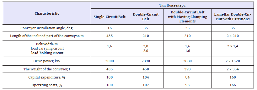
Technical and economic evaluation of the effectiveness of the use of steeply inclined double-circuit conveyor with moving elements in comparison with other types of conveyors is carried out for the conditions of the career of Kachar CFT (Table 3).
Table 3:Indicators of application of conveyor transport of rock mass in the career of Kachar MSP (H=120m, Q=21 million tons/year).
Summary
As a result of the research, the theoretical foundations and practical prerequisites for the development of design documentation for the creation of steep conveyor lifts with moving synchronously with the belt clamping elements in the form of elastic corrugations are created.
A schematic diagram of a two-circuit steeply inclined belt conveyor with moving clamping elements is developed. A feature of the design is the performance of clamping elements in the form of corrugations fixed to the outer (working) surface of the belt of the load-holding circuit. Corrugations are made of elastic-elastic material (for example, conveyor belt), have good damping ability and restore their shape after the disappearance of contact with the transported material. The maximum height of the corrugation corresponds to the depth of the gutter of the load-bearing tape, and in the absence of rock mass on it, the corrugation enters its gutter and performs the function of a partition. The conveyor design is protected by the RF patent.
The design features of the steeply inclined belt conveyor with moving clamping elements in the form of corrugation, provide a reliable rise of uneven flow of rock mass due to: the joint use of forced pressing of the transported material in the chute of the load-bearing tape and the effect of deep groove; synchronous with the load-bearing tape movement of clamping elements, elastic properties of clamping elements, allowing them to perform the function of additional support of the transport material.
The use of steeply inclined conveyors with moving clamping elements can significantly increase the completeness of the technical capabilities of the equipment. So its coefficient of use of technical capabilities, determined by the product of the coefficients of the use of equipment in time and performance, has a value of 0.56-0.6, which is almost twice as high as this indicator of the steeply inclined conveyor with stationary clamping elements in the form of rollers (0.27-0.29), installed at the quarry of Muruntau Navoi GOK [5] (Uzbekistan).
It is established that at the annual performance of complexes 5-0 million tons steeply inclined conveyors should be used in the heights of the rock mass over 100-200m. Under these conditions, at a lower operating cost (5-20%) specific capital costs for complexes, steeply inclined conveyors significantly (13-30%) lower. In addition, the use of steeply inclined conveyors is preferable in terms of labor productivity per worker of the CFT complex (higher by 8-20%). With the increase in productivity of the CFT complexes to 20-30 million. CFT steeply inclined conveyors should be used for lift heights of rock mass, more than 200-300m. under these conditions a small difference in the specific operating costs (less than 10%), capital costs for complexes of CFT with steeply inclined conveyors below 10-22% [11,12].
References
- Karmaev GD, Glebov AV (2012) Selection of mining and transport equipment of cyclic-flow technology of quarries. Ekaterinburg: IGD Uro ran, p. 295.
- Nikolaev ED (1998) Analysis of structures steeply inclined conveyors for deep pits. Mountain magazine 11-12: 62-65.
- Kotyashev AA, Kaledin AV (1990) Application of belt high-angle conveyors for transportation of rock mass. Mining Journal 5: 61-63.
- Sheshko EE, Morozov VI, Burr NG (1996) Perspectives of steeply inclined conveyor lifting for mining. Mining Journal 6: 56-59.
- Olenegorsky GOK launched a crushing complex in a quarry with the KNK [Electronic resource]: access Mode.
- Semeniuk AA, Reshetnyak SP, Baichurin NI, Sultanova NR (2015) The innovative technology of transport Olenegorsky ore deposits with the application of the steeply inclined conveyor. Mining Information Analytical Bulletin, pp. 413-420.
- Kirichenko AI, Burr AN (2010) Steeply inclined conveyor KNK 270 for the Navoi mining-a new stage of development of the CCT. Mining Industry 2(90): 71.
- Burr AN (2003) Prospects of application of steeply inclined conveyors with pressure belt at the CCT. Mining Journal 6: 52-56.
- Stanisic Z, Dos Santos JA (1997) In-pit crushing and high angle conveying at copper mine. Bulk Solids Handling 17(1).
- Yakovlev VL, Tyul’kin PA, Garmaev GD (2002) Technological aspects of the application crotonylene conveyors in mining industry. Mining Information Analytical Bulletin 2: 211-217.
- Kamaev GD, Bersenev VA, Semenkin AV, Sumina IG (2014) Technical and technological aspects of application of steeply inclined conveyors in quarries. Problems of Subsoil Use. - № 3 [Electronic resource]: Network Periodical. Ekaterinburg: IGD Uro ran, pp. 154-163.
- Glebov AV, Bersenev VA, Karmaev GD, Semenkin AV Pit. Patent RF №2632612. The decision on patent grant from 03.07.2017.
© 2018 Glebov Andrey Valerjevich. This is an open access article distributed under the terms of the Creative Commons Attribution License , which permits unrestricted use, distribution, and build upon your work non-commercially.
 a Creative Commons Attribution 4.0 International License. Based on a work at www.crimsonpublishers.com.
Best viewed in


.jpg)


 Editorial Board Registrations
 Submit your Article
 Refer a Friend
 Advertise With Us
.jpg)


.jpg)


.bmp)
.jpg)
.png)
.jpg)


.jpg)


.png)

.png)


.png)


