
- About Us
- Information
-

The Author ensures that the research has been conducted responsibly and ethically with adherence to all relevant regulations. read more..
- For Authors
- For Reviewer
- Manuscript Guidelines
- Membership
- Publication Ethics
-
- Journals
- Reprints
- e-Books
- Videos
- Policies
- Contact Us
 COVID-19
- Submissions


Full Text
Academic Journal of Engineering Studies
A Dynamic Model for Preliminary Design of Vertical Tail Plane
Valentin Bon* and Yves Gourinat
Higher Institute of Aeronautics and Space-Supaero, University of Toulouse, France
*Corresponding author: Valentin Bon, Higher Institute of Aeronautics and Space-Supaero, University of Toulouse, France
Submission: March 11, 2021 Published: March 23, 2021
.jpg)
ISSN:2694-4421 Volume1 Issue5
Abstract
The purpose of this article is to focus on the development of a significant structural element of the aircraft, namely the Vertical Tail Plane-VTP. The paper will detail the static and dynamic model designed to propose a new certification tool for the certification authorities. At the end of this paper, the dynamic model proposed here will be used with an example of the Saturn V’s behaviour in order to validate its robustness and reliability.
Keywords: Aircraft design; Structural technology; Integrated optimization; Vertical tail plane
Introduction
Aircraft digitalization, operations, and support have become an essential component for all aviation business actors, taking an increasingly important place through the production of a large volume and a wide variety of operational data. At the preliminary design stage, this new situation leads to taking into account criteria such as operations, maintenance, economic added value, development time, or certification. The data flow and decisions resulting from their analysis - by more or less complex algorithms - are mainly elements aimed at optimizing availability and Direct Operating Cost (DOC) of aircraft. It also allows the optimal definition of systems by using resources and services dedicated to health monitoring, advanced maintenance, and operational support. These operational data flows also open up highly relevant perspectives for challenging current de-sign and certification methods that rely on robust and proven solutions, often underpinned by conservative assumptions in certification regulations. The certification of an aircraft can today be perceived as a ”fire-and-forget” process in which the conformity of the design is verified based on assumptions relating to the aircraft’s operation. (cf. ”Introduction to EASA guidelines” in Guidance Material 21A.3B -EASA Part 21) [1] This may not be verified or challenged after the issuance of the type certificate. Similarly, a Vehicle Health Management system will rely on data to improve the reliability of an aircraft and its equipment (through a better understanding of their condition, advanced predictions, or predictive maintenance). It is relevant to study how the use of this large volume of information can optimize the preliminary design of the aircraft and the certification assumptions here above mentioned.
This research aims to develop a disruptive methodology and associated multidisciplinary models for preliminary design and certification of an aircraft taking into account operational data flows and, more broadly, digitalization contributions. The objective of this methodology is to redefine the cur-rent assumptions or requirements through dynamic management of the knowledge of the real state of an aircraft and its operational and physical environment. This knowledge management process would help reduce the operational uncertainties that now lead to existing conservatism. By declination would allow for optimized designs and more relevant certification while ensuring compliance with the adequate safety objectives. Datamodels built and updated based on these data flows would be used to create, improve, and set up preliminary design calculation bricks. Those will be compatible with the multidisciplinary aircraft design tools used by ISAE-SUPAERO and Research Federation (FAST, Open MDAO). A probabilistic approach of dimensioning and certification criteria could also be introduced in the computational bricks, making it possible to challenge hard criteria applicable today. Finally, a demonstration of the new proposed rules could be considered to verify, based on test-cases of increasing complexity, the coherence of the disruptive methodology developed. It could be achieved by prototyping or virtual test integrating changes of sizing rules and using a loop of integrity control. The main objective of this paper is to present a rough and very useful static and dynamic model of the vertical tail plane. This will help the certifier to propose and check a preliminary design of a vertical tail plane.
Context
The first step is to understand the needs and function’s requirements of all related parts of the Vertical Tail Plane. The first step was to identify the requirements, especially the ones given by the certification authorities, then they were examined and submitted; this will help respect these in the system architecture further, making it easier to show compliance during the certification process. The purpose of the vertical tail plane has to be understood. For the manufacturer and the aviation authorities’ approval, the primary functions of the vertical tail plane are to control and stabilize the aircraft. Therefore, it is necessary to manufacture a system that provides these functions. Additionally, all other regulations stated in the certification have to be respected to have a successful concept and a certified aircraft at the end (Figure 1).
Figure 1: Paper’s context.

Materials and Methods
Static analysis
In this paper, the design was intended to be as simple as possible; for instance, the EASA or FAA certification engineer will do the same to have a big picture of the design component. Thus, the vertical tail plane of an A320 has been model as a tapered beam box of rectangular cross-section. The first thing to know is that the vertical tail plane of the A320 is tightened to the rear fuselage on six brackets. The study could have been modeled as a clamped beam, nevertheless, in mechanical engineering, nothing is perfect, and the vertical tail is not clamped. In reality, it behaves as a ”rigid-flexible” beam. In this way, in one end, the tapered beam will be constrained by a rotational and a translational spring (kr and kt) model by a rectangular beam [2,3]. For this design, the Bernoulli-Euler beam theory has been used with the two primary assump- tions: plane sections remain plane, and that the slopes are small (Figure 2). Other more sophisticated models exist, such as the Timoshenko beam theory; however, the Bernoulli-Euler assumptions typically provide answers that are good enough for design in most cases. The tapered beam is supposed to vary linearly in width and depth along its length.
Figure 2: Tapered Euler-Bernoulli beam with flexible boundary conditions.

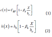
Where
CRV Width at the root of the vertical tail plane;
bv Vertical Tail Plane span;
βb Width degree of taper = 1–width taper ratio;
βh Height degree of taper = 1–height taper ratio.
The lateral deflection of the beam is then expressed as: [2]
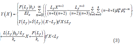
With
F (Lf ) Lift force applied at the aerodynamic center of the Vertical
Tail Plane;
Lf Dimensionless length equal to lf ;
The objective of this part was to understand the behavior of the
VTP in order to carry out a dynamic study of the vertical tail plane.
Dynamic Analysis
The static analysis is now completed so that the dynamic analysis can be described in detail. For this article the investigation have been done analytically. The resulted model will be slightly robust and accurate compared to numerical analysis where numerical modes can appear and skew the results.
Magnitude check
In this paragraph, a uniform beam in flexion follow the classic dynamic equation EIV+ρSV=0, derived from the Bresse static equation EIzV−λY = 0 using Kirchhoff hypothesis.
As the beam is clamped, the equation obtained is the following:
f (X)=A(cos(ΩX)−ch(ΩX))+B(sin(ΩX)−sh(ΩX)) (4)
In this particular case, for a clamped free beam, the boundary conditions the systems admit dynamics solutions if is the root of the following equation:
1+cos(ΩL)·ch(ΩL)=0 (5)
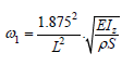
The first root is strictly positive of this equation gives:
ΩL=1.875
Numerical application
With a mean beam with a length (L) of 6.2554m, a height (h) equal to 0.3781m, a width of 3.4371m, and a uniform thickness the parameters are obtained are the following: IZ=2.6311·10−3m4, E=49GPa, and ρ=1550kg/m3.
 (6)
(6)
By doing the computation, the frequency for the first mode is then obtained:
f1=14.27Hz
This first computation gives an order of magnitude of the expected result for the tapered beam’s model. The dynamic analysis of tapered beams with rotational and translational springs is being studied. The De Rosa-Auciello [4] paper present this problem in which the frequency equation has been solved. As compute previously the translational and rotational stiffness are very high. So, when the non-dimensional stiffness coefficients are defined as follow:
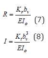
Where
kr Rotational spring stiffness;
kt Translational spring stiffness;
I0 Second moment of area;
It appears that both coefficients R and T tends to infinity. Thus, the determinants are equal to the determinants given by the Mabie-Rogers’s paper [5]. With the new boundary conditions, the new solution are obtained:
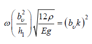 (9)
(9)
With
ω Angular frequency
h1 Height of the Vertical Tail Plane
ρ Material’s density
E Young’s modulus;
g Gravity;
k Spring stiffness
In Mabie-Rogers paper [5], β and α are the width and height reverse taper ratio equal to 3.3. In (Figure 3), (lk)2=19.2 is obtained, and it can be deducing the fundamental frequency of the tapered beam. Something to take in consideration is that this study was done with imperials units. So, all the data have been converted into it with bv =6.2554m, h1=0.17m, E=49GPa, and ρ=1500kg/m3, and g=9.81m/s2
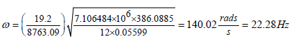 (10)
(10)
The fundamental frequency is then computed:
f=22.28Hz
The hypothesis set in this report allows us to take 22Hz for the first frequency. This result was excepted as 14.3Hz was obtained from the magnitude mean beam, and because of a shorter tip than the mean beam, the frequency excepted was higher. Still, the magnitude is correct; the preliminary design with a mean uniform beam is rough. So, to be sure of the magnitude, this paper will go further and developed a discretized beam. Figure 3, from [5] define the way to find the coefficient (bvk)2 to be able to compute the frequency. In this example, the degree of taper ratio of the beam is equal to α=3.3(bvk)2 and then deduced to be equal to 19.2.
Figure 3: Frequencies for double-tapered cantilever beam with free end with β=α [5].

FEA model verification
To validate the previous model, an equivalent beam made of 10 elements - here uniform beams - was studied on Abaqus. Each element has the same length of 625.54mm, a width from CRV to CtV decrementing by 408.57mm every element. (Figure 4) After adding the adequate properties inside the software, the first mode was obtained (Figure 5) with a frequency equal to:
Figure 4: Side view of the discretization of the tapered box beam by 10 uniform sections.

Figure 5: First mode of the discretized 1000 sections beam on Abaqus.

f=26Hz
The frequency from the tapered beam model is still closed to the discretized model for the certification. The discretization can explain the difference in one hand, but also by the number of elements used, yet for the certification, the model is valid. To have a better result the same thing has been done with this time 1000 sections. The result obtained (Figure 5), give a better result, as the model is more precise. The frequency obtained is equal to:
f=24.97Hz
The frequency of 22.28Hz, computed using the tapered beam model is still close to the dis-cretized model for the certification (Figure 6). The discretization can explain the difference in one hand, but also by the number of elements used. Yet, the model is valid for the certification as a simple model very close to the final result is needed, only a 12 % difference between 22.28Hz and 24.97Hz (Figure 7). This part of the article proposes a model for the certification process, to have a preliminary concept to validate the proposed Vertical Tail Plane [6]. Let’s conclude on the essential points of this model. For certification model three levels are asked to justify the model usefulness:
Figure 6: First mode of the discretized Saturn V.

Figure 7: Saturn V Stages [6].

Precision - This modelling process is not precise, in spite of this, it is not what is sought in priority for this paper and for the certification.
Robustness - Whereas this model is robust for the reason as it is simple and give a clear overview of the preliminary design.
Reliability - Moreover the reliability is great as that the result obtained are closed to the expected one.
This modelling process is a first version that requires smoother edges, but which already allows us to have a promising approach for Vertical Tail Plane certification. It can be shaped as the certification engineer want, with the material property of the part involves in the design, the speed of the aircraft, all the aerodynamic coefficient, the shape of the beam, the force apply on it, the position of the force, and all the Vertical Tail Plane parameters.
Thermal model
The model proposed in statics and dynamics is also valid in linear thermo elasticity, with a simple extension. The Bresse- Duhamel equation remains valid:
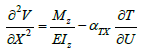 (11)
(11)
Where
αTX Coefficient of structural thermal expansion along the longitudinal axis X of the beam;
∂T Temperature gradient along the transverse Y-axis of the beam
The fourth-degree interpolation on the quadratic moment IZ in bending is still pertinent, and Kirchhoff’s assumption can be extended. Indeed, the temperature map in the cross-section can be assimilated to a linear distribution, on the one hand because the extreme panels are thin and therefore at approximately uniform temperature and on the other hand because the possible stringers and fluids binding these panels smooth the temperature gradient.
Thus, subject to the linear behaviour of the materials, the additional Duhamel’s term is reduced to a function of XαT XΓ(X) where Γ is the thermal gradient in the current straight section. This function is simply implemented into the proposed model, and fully consistent with it for the representation of the box itself. It remains to represent the conditions of support, thermally. This can be carried out by a symmetrical linear bimetallic strip. This element is made up of two bi-clamped identical prismatic beams, identified with the junction linking the two panels of the box to the strong frames or internal boxes of the fuselage. Consequently, the thermal rotation induced by the gradient Γ at the box root is given by:
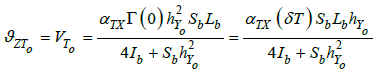 (12)
(12)
Where
hY0 Height of the box at its root, along the Y-axis;
Sb, Lb, Ib Cross-sectional area, length and quadratic moment of each bimetal beam;
δT Difference of temperature between the two main panels of the box.
With these two elements – Duhamel term in beam equation for the box itself and bimetallic strip for the support boundary condition – the proposed model is well adapted for the thermo elastic analysis.
Saturn V Model
Figure 8: Comparison of 1/10 scale and full-scale test results of first and second pitch nodes-100 percent propellant [7].

To end this paper, this model was used to find the first mode of the Saturn V rocket by modeling the S-IC, S-II, and S-IVB stages. (Figure 8) from NASA indicates a first mode frequency of 1.11Hz with 100 % of propellant. So, knowing the dimension of the three main stage present hereafter, a finite element analysis on the three main stage was possible [7]. By using the previous model the first frequency of the Saturn V was computed and a frequency of 1.61Hz has been identified with a hollowed structure and 0 % of propellant. The difference can be explained by the mass of the propellant not taken into account, and of course the simplification of the model.
Conclusion
All things considered, this research emphasis on a new method to study the vertical tail plane. As presented previously, this model is good for the certification as it is robust and reliable. It will help the certifier to check and have a preliminary design for the final product. The static, dynamic, and thermal models presented in this paper gives suitable results for the certification authorities. The difference between the discretized model and the analytic model is acceptable. This suggests that the presented model here can be used for the wings and the fuselage of an aircraft from any size, and also it could be use in other domain like space launchers, with the Saturn V model validated in this paper. The coupling between different disciplines is important and a multidisciplinary design approach is essential. The focus of this article stems from these observations.
Acknowledgment
This work was supported by the Department of Mechanics, Structures and Materials (DMSM) and the Department of Aerospace Vehicles Design and Control (DCAS). The authors would like to show their gratitude for the opportunity given to perform this research, and we thank reviewers for their so-called insights. We are also immensely grateful to everyone for their comments on an earlier version of the manuscript, although any errors are our own and should not tarnish the reputations of these esteemed persons.
References
- (2002) European union aviation safety agency, Germany.
- Wang L, Yang Z (2011) Identification of boundary conditions of tapered beam-like structures using static flexibility measurements. Mechanical Systems and Signal Processing 25(7): 2484-2500.
- Wei L, Zhichun Y, Le W, Ning G (2019) Boundary condition modelling and identification for cantilever-like structures using natural frequencies. Chinese Journal of Aeronautics 32(6): 1451-1464.
- Rosa MD, Auciello NM (1996) Free vibrations of tapered beams with flexible ends. Computers & Structures 60(2): 197-202.
- Mabie HH, Rogers CB (1974) Transverse vibrations of double-tapered cantilever beams with end support and with end mass. The Journal of the Acoustical Society of America 55(5): 986-991.
- NASA (1969) Saturn V Flight Manual SA 507, USA.
- Grimes PJ, Tigue LM, Riley GF, Tilden DI (1970) Advancements in structural dynamic technology resulting from Saturn 5 programs. NASA, USA.
© 2021 Valentin Bon. This is an open access article distributed under the terms of the Creative Commons Attribution License , which permits unrestricted use, distribution, and build upon your work non-commercially.
Editor In Chief


.jpg)


Signup for Newsletter

Quick Links
 Editorial Board Registrations
 Submit your Article
 Refer a Friend
 Advertise With Us
Our Recent Edition

.jpg)


Top Editors


.jpg)


.bmp)
.jpg)
.png)
.jpg)


.jpg)


.png)

.png)


.png)


Financial Support

Sponsors

Latest e-Books

Latest Video

 a Creative Commons Attribution 4.0 International License. Based on a work at www.crimsonpublishers.com.
Best viewed in
a Creative Commons Attribution 4.0 International License. Based on a work at www.crimsonpublishers.com.
Best viewed in