
- About Us
- Information
-

The Author ensures that the research has been conducted responsibly and ethically with adherence to all relevant regulations. read more..
- For Authors
- For Reviewer
- Manuscript Guidelines
- Membership
- Publication Ethics
-
- Journals
- Reprints
- e-Books
- Videos
- Policies
- Contact Us
 COVID-19
- Submissions


Full Text
Advancements in Civil Engineering & Technology
Stress-strain State of Orthogonally Intersecting Shells and Surrounding Soil Considering Construction Stage Analysis
Miller Mark1*, Fang Yong1, Akulich Vladimir2, Kositsyn Sergey2, Kharitonov Sergey3 and Noskov Ivan1
1Key laboratory of Transportation Tunnel Engineering of Ministry of Education, School of Civil Engineering, Southwest Jiaotong University, China
2Department of Theoretical Mechanics, School of Railway Track, Structure and Construction, Russian University of Transport (RUT MIIT), Russia
3Department of Bridges and Tunnels, School of Railway Track, Structure and Construction, Russian University of Transport (RUT MIIT), Russia
*Corresponding author:Miller Mark, Key laboratory of Transportation Tunnel Engineering of Ministry of Education, School of Civil Engineering, Southwest Jiaotong University, Chengdu, China
Submission: May 26, 2025;Published: June 20, 2025

ISSN: 2639-0574 Volume6 Issue 5
Abstract
The paper presents a numerical analysis of the effect of taking into account the stages of construction on the stress-strain state of a tee joint interacting with a soil array. The study of such systems is in demand by modern practice. For example, during the construction of the subway, there is always a need for tunnel connection structures that ensure the functioning of the main tunnels and stations. Calculated cases with a different number of stages of construction (0, 1, 2, 4, 8 and 40) tee connection have been compiled and the results were obtained. It is established that the correct accounting of successive stages of construction plays a key role in correct determining the stress-strain state of the shell-ground systems.
Keywords:Tunnel; Cylindrical shell; Finite element method; Stress-strain state; Surface settlement
Introduction
Modern megacities are facing a growing need for the development of transport infrastructure, and underground construction, in particular the laying of subway tunnels, is becoming a key solution to the problem of congestion in road networks. In recent decades, subways have become widespread around the world, from historic systems in London, Moscow and New York to modern high-tech lines in Shanghai, Dubai and Singapore. In conditions of dense urban development and limited underground space, tunnels are increasingly laid at different levels, which lead to their intersections, including orthogonal ones [1-4]. Such engineering solutions require a thorough analysis of the stress-strain state of the soil mass and structures, since the interaction of tunnels can significantly affect their stability and operational safety. Taking into account the stages of construction is particularly difficult, since successive tunnelling leads to a redistribution of stresses in the surrounding array. Incorrect strain-stress state assessment can cause unacceptable deformations, damage to the lining, or even emergency situations. In this regard, numerical modelling, in particular the finite element method (FEM), is becoming an indispensable tool for predicting the behavior of underground structures at all stages of construction.
The practical implementation of numerical modelling of intersecting tunnels in design practice faces a number of serious challenges. The main problem is the need for detailed consideration of all construction stages, which requires the creation of complex threedimensional models with step-by-step analysis of each tunnelling phase. This leads to a significant increase in computational resources and calculation time, which in conditions of limited design deadlines often becomes a crucial factor. The financial consequences of implementing such an approach in routine design practice include not only direct costs for high-performance computing equipment and specialized software, but also the need to train qualified specialists. However, ignoring the construction phases can lead to significantly more serious financial losses.
Existing approaches to designing intersecting tunnels, based on simplified analytical methods or two-dimensional modelling of individual sections, are often unable to fully consider the complex spatial interaction of structures.
In this study the model of orthogonally intersecting cylindrical shells interacting with the surrounding base is developed, taking into account the above features, which provides a new level of computational justification of such systems.
Materials and Methodology
The numerical analysis was performed in the ANSYS Mechanical software package [5-9], which allows calculating the static stressstrain state of arbitrary combined spatial structures, taking into account the effects of physical, geometric, contact and genetic (stages of construction and loading) nonlinearities based on the finite element method. To verify the results and obtain a more detailed picture, Midas GTS NX software [10] was also used, which specializes in the numerical simulation of geotechnical problems. Geometrically, the calculation schemes in both software packages are identical, but Midas provides a much more extensive set of available tools for generating mesh sets, adjusting construction stage sequence, specifying shell-ground friction and solver settings.
The spatial calculation model consists of orthogonally intersecting cylindrical shells (a tee joint) and a surrounding soil array. The main cylindrical shell has diameter D1 = 5.50m and thickness t1 = 0.25m; the adjacent shell has diameter D2 = 3.85m and thickness t2 = 0.20m. The shell material is given by an ideally elastic material with properties closed to concrete: elastic modulus E = 30,000MPa, Poisson’s ratio μ=0.2, density ρ=2300 kg/m3. The soil material is given by the elastic-plastic Mohr – Coulomb model (O. Mohr, C. A. Coulomb) with the following parameters: deformation modulus Egr=30MPa, transverse deformation coefficient μgr=0.3, density ρgr = 2000kg/m3, adhesion C = 10kPa, internal friction angle φ=25°.
Boundary conditions are set for the lower and lateral surfaces of the soil array and the edges of the tee joint, which ensure geometric immutability and correct operation of the system under consideration. The load is applied to the structures only from selfweight.
The node of orthogonally intersecting cylindrical shells is located at a depth of 30m from the upper surface. The sizes of the soil array are selected from the condition of boundary condition non-influence on of the stress-strain state and 5 diameters of the large shell to the left and right borders are assumed. Figure 1 shows a general view of the calculation model and a view of the tee joint.
Figure 1:General view of the calculation model (left) and view of the tee connection (right).

When solving the problem with ANSYS, contact nonlinearity is taken into account [11]. The contact between the structures and soil is made using contact pairs located on the outside of the tee joint and on the surrounding array. The contact area before solving the problem is unknown. Depending on loads, material properties, boundary conditions and other factors, surfaces can come into contact with each other and quit it. The calculation of contact interaction was performed using the penalty method, which is implemented in the ANSYS Mechanical software package [2,12]. In these calculation models, the possibility of the tee joint detaching from the surrounding base is taken into account, but contact friction between objects is not considered.
Calculated cases were compiled without stages and with 1, 2, 4, 8 stages of the construction of the tee joint. In each case, an additional one zero stage was assigned to determine the initial conditions of the whole system. The main cylindrical shell D1 was activated first; the adjacent shell of D2 was activated second.
As noted earlier, Midas GTS NX has a much broader functionality for the approach to solving this problem, since it is a specialized software package for solving geotechnical tasks. The tunnels are modelled using shell elements and “extracted” from the surrounding soil mass, which allows for the implementation of node-to-node contact interaction. For this purpose, a homogeneous element of the “interface” type was used, which simulates the interface behavior between ground and structure having large relative stiffness difference.
A different approach to modelling has been adopted: to obtain a more detailed picture, two different stage analyses have been implemented.
For the lining stress state, zero stage was used to set up initial stress distribution in the soil array; the installation of the main shell was divided into 20 stages, at each of which the soil was simultaneously removed and the tunnel lining was installed at a depth of 2 meters. Then part of the main shell in the area of abutment was removed and another 19 stages were allocated for the construction of the adjacent shell with a 1.5meter pitch. At the last stage, the interface elements between the lining and the soil were activated, thus, the calculation is presented in 40 stages, taking into account the initial conditions, at which the initial stress state is set; the primary soil array and displacements are reset.
To determine the surface settlement values, a previously well-proven approach [13] is used, in which “contraction” load is applied. This tool is a percentage reduction in the length of the shell along the perimeter, which obviously distorts the stress state of the tunnel lining and cannot be used in strength calculations. But this approach allows one to model the soil volume lost, which inevitably occurs during the construction of tunnels using the shield method and is the main cause of deformation of the ground surface. In this second stage analysis case, “contraction” load is applied to the shell of the main tunnel after its complete construction, and then the stages follow without changes.
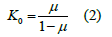
In order to find the optimal combination of solver settings, 3 calculation cases were formed and calculated, which differ from each other by activating/deactivating K0 condition and geometric nonlinearity.
The K0 method uses the constant to calculate the horizontal stress from the vertical stress to set it as the in-situ stress:

Using this method, the vertical stress needs to be found first using self-weight analysis and that value can be used to compute the horizontal stress. Here, the shear stress maintains its value, calculated from the analysis result. If the ground surface is horizontal, there are no problems in using this method, but if not, the calculated stress state and self-weight is not in equilibrium.
If the stress is adjusted without maintaining the equilibrium state, the stress can change to fit the equilibrium with the external force in future stress analysis, even if there are no external force changes, causing deformation. Hence, the method can be applied if the additional stress changes are relatively small.
If the K0 condition is not activated, then the gravity loading method is applied by default and the K0 value is equal to:
In this case the stress state obtained from the self-weight analysis is set as the in-situ stress. More reasonable behavior of the structure can be obtained considering geometric nonlinear effect. This can be useful in the presence of large deformations or load nonlinearity which is reflecting the effects of follower loads, where the load direction changes with the deformation.
Considering the above, depending on the combinations of activated solver settings, 3 calculation cases (Table 1) have been compiled, each of which has 2 stage analyses to determine the stress state of the tunnel lining and ground surface settlement.
Table 1:Three calculation cases with different solver settings.

In order to verify the numerical simulations results, the diagram of ground surface settlement was obtained analytically using the Park solution for deep tunnels [14]. In polar coordinates the displacements have form:
Ground surface settlements can be expressed as:

where E is Young’s modulus, r and θ are the polar coordinates (Figure 2), γ is the unit weight, a is the tunnel radius, a0 is the coefficient depending on boundary conditions (Figure 3).
Figure 2:Accepted calculation scheme in polar coordinates system.

Figure 3:Boundary conditions of prescribed displacements BC-1 (left) and BC-2 (right).

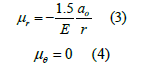
Prescribed displacements have taken with two kinds of boundary conditions (BC-1 and BC-2), which are described by formulas:

The value u0=0.5g and g=gap parameter estimated by following the procedure suggested by Lee [15].
Results
Based on the calculations, a comparative analysis of the maximum equivalent von Mises stresses in orthogonally intersecting cylindrical shells were carried out. The curves of stress changes in the shell depending on the number of stages in the design case are shown in Figure 4, which are obtained by ANSYS software.
Figure 4:Maximum equivalent stresses (von Mises) in orthogonally intersecting cylindrical shells [9].

Additionally, a marker on the graph indicates the maximum equivalent stress value in the tee connection without taking into account the stages of construction.
According to the results, it can be seen that the construction stage calculation gives a significant change in the values of the von Mises stresses in the tee joint compared with the calculated case without taking the stages into account. In the case of 8 stages of construction, the maximum equivalent von Mises stress in the shell is 75.2MPa, while without considering the stages, the maximum equivalent stress in the shell is 105.6MPa.
The von Mises stresses σe [17-20] are determined by the formula:

where σ1, σ2, σ3 are the principal stresses.
The distribution of the shell stresses in the case of 8 stages of construction is shown in Figure 5. The maximum stress values occur at the linking of the shells.
Figure 5:Distributions of maximum equivalent stresses (von Mises) in the body of cylindrical shells (the connection of shells is shown on the right) [9].

Figure 6:Maximum equivalent stresses (von Mises) with 40 construction stages.

The results of the analysis of the same calculation scheme in Midas GTS NX software are shown in Figure 6.
The solver settings are selected as indicated above (Table 1): without taking into account geometric nonlinearity with deactivated (CASE 1) and activated (CASE 2) condition K0; taking into account geometric nonlinearity and activated condition K0 (CASE 3). The values of maximum equivalent von Mises stress for each case are 72.0, 70.3 and 75.9MPa, respectively.
The distribution of the shell maximum equivalent stresses in the case of 40 stages of construction is shown in Figure 7. The maximum stress values occur at the linking of the shells.
Figure 7:Distributions of maximum equivalent stresses in the shells at the construction stage №39.

To determine the amount of ground surface settlement, the tool “contraction load” is used, which is set as a uniform shrinking of a cylindrical shell with a decrease in radial length. It is important to note that the stress-strain state of the shell is distorted in this case, since in reality there is no such load, but this approach allows one to simulate the soil volume lost arising because of the gap between the outer shell of the tunnel boring machine shield and the tunnel lining structure [13]. Thus, the calculation of surface settlement is carried out by analogy with the calculation of the stress state of the lining, with the only difference that at the end of the construction of the main shell (stage 20), an additional contraction load is set on the shell.
Then, analytical solution of Park [14] for deep tunnels with two types of boundary conditions is used as a verification of the numerical simulation. The results for two flat calculation schemes of the main and secondary shells are sequentially obtained, the results are summarized and the diagram of the ground surface settlements above the axis of the main tunnel is plotted. The results are presented in Figure 8.
Figure 8:Diagrams of ground surface settlements.

According to the numerical simulation models, the maximum settlement value is located directly above the junction point of the shells: CASE 1 – 0.00515m; CASE 2 – 0.00759m; CASE 3 – 0.00770m. The analytical solution gives different values of precipitation depending on the boundary conditions: BC-1 – 0.00408m; BC-2 – 0.00818m.
Discussion
The effect of taking into account construction sequence of a tee joint on its stress-strain state is considered. The results obtained in ANSYS indicate that in the case of 8 stages of construction, the maximum equivalent von Mises stress in the shell was 75.2MPa, while without taking into account the stages, the stress was 105.6MPa. Then detailed calculation was performed in Midas GTS NX, the number of stages was increased to 40 in three different cases of different combinations of solver settings and maximum values of 72.0, 70.3 and 75.9MPa were obtained in cases 1, 2 and 3 respectively.
It follows from Figure 4 that with 8 stages taken into account, the maximum stress value is reached at stages 5-6 with subsequent unloading. This feature is obviously confirmed by the calculation with 40 stages. At the end of the construction of the main shell (stage 20), a part of it is dismantled for the construction of the secondary shell, and at this moment there is a sharp increase in the maximum values of von Mises stresses, which reaches a peak at stage 23 (Figure 6). Further, as the construction of the shell continues, unloading occurs and the stresses decrease. This pattern is well observed for all calculated cases with any combination of solver settings.
As for the calculated cases themselves, it should be noted that the activation/deactivation of the K0 condition plays a key role in determining the stress-strain state of the entire system. Figure 6 shows that, depending on the chosen method of setting the initial horizontal stresses (K0 or gravitational loading method), the distribution of maximum stresses in the shell changes (stages 0-20). When the maximum value is reached (stage 23), further stress redistribution is determined by the option of activating/ deactivating geometric nonlinearity.
It can be seen from Figure 8 that the value of surface settlement also varies with changes in the solver settings. The difference between cases with the activated/deactivated geometric nonlinearity option is minimal. In addition, it is worth noting the solutions obtained analytically, according to which the settlement is the largest or the smallest, depending on the initial boundary conditions. These two values are the boundaries of the interval within which all numerical solutions are obtained. Thus, the Park solution can be a useful verification tool when designing real engineering projects.
In Midas, friction was set using shell interface elements with a stress reduction factor. In each of 3 cases, these elements were activated after the construction of both shells and changed the stresses and displacements by hundredths of a percent. Thus, friction does not play an important role in this particular task and can be ignored.
For practical calculations of spatial schemes, it can be recommended to activate the K0 condition because of the better convergence of the solution. Although the stress values are redistributed several times, the absolute maximum value of the von Mises stresses in the shell are obtained precisely by using the K0 condition, what can be critical when performing structural strength calculations. The situation is more complicated with geometric nonlinearity: although both stresses and surface settlements are greater when this option is activated, such a calculation requires much more computing resources and time; in this case, the choice should be made based on deadlines and available hardware.
The results obtained showed that taking into account the sequence of construction significantly affects the stress-strain state of orthogonally intersecting cylindrical shells and the surrounding soil array. The prospects for further research are related to the use of nonlinear shell materials [8,21-25] and various options for the contact interaction of the shell and the soil.
In the future, it is planned to expand loading scenarios by considering various operational and installation loads, enhancing the practical value of the results. Operational loads should include dynamic effects from train movement, thermal loads, changes in groundwater level, and seismic loads. Installation loads include impacts from construction equipment, temporary structures, and technological breaks in construction. This approach will allow obtaining a more complete picture of the stress-strain state of the system and developing well-substantiated recommendations for designing real objects.
In addition, analysis of model sensitivity to such parameters as soil properties, shell parameters, and variations in construction sequence will be considered. Parametric analysis of shell thickness will allow determining optimal structural solutions taking into account economic efficiency while ensuring the required level of safety.
Declaration of Interest
The authors report there are no competing interests to declare.
Data Availability Statement
The data that support the findings of this study are available from the corresponding author, M. M., upon reasonable request.
References
- Basov KA (2005) ANSYS: User reference. DMK Press, p. 640.
- Belostockij AM, Golovin VV, Fradkin BV (1985) Method of calculating the stress state of tee joints of pipes with complex loading. Collection of scientific works of the Gidroproekt 100: 83-93.
- Klochkov Ju V, Nikolaev AP, Kiseleva TA (2013) Comparison of stresses calculated on the basis of scalar and vector interpolation of FEM in articulated shells of dissimilar materials. Construction Mechanics and Calculation of Structures 5: 70-76.
- Kositsyn SB, Chan Suan Lin (2014) Numerical analysis of the stress–strain state of orthogonally intersecting cylindrical shells without taking into account and taking into account their unilateral interaction with the surrounding soil mass. International Journal for Computational Civil and Structural Engineering. 1: 72-78.
- Bate K, Vilson E (1982) Numerical methods of analysis and the finite element method. Strojizdat, p. 446.
- Gallager R (1984) The finite element method. Fundamentals. Mir, p. 429.
- Trushin SI (2008) Finite element method. Theory and problems. Izdatel'stvo ACB, p. 256.
- Zenkevich OK (1975) The finite element method in engineering. Mir, p. 542.
- Zolotov AB, Akimov PA, Sidorov VN, Mozgaleva ML (2009) Numerical and analytical methods for calculating building structures. Izdatel'stvo ACB, p. 336.
- Midas GTS NX 2014 v2.1 Analysis reference / MIDAS Information Technology Co. 2014.
- Kositsyn SB, Chan Suan Lin (2013) Comparative analysis of various models of the soil surrounding the cylindrical shell, taking into account the possibility of its detachment from the shell. International Journal for Computational Civil and Structural Engineering 1: 65-72.
- Zhao W, Zhang J, Zhang W, Yuan X (2021) Internal resonance characteristics of hyperelastic thin-walled cylindrical shells composed of Mooney-Rivlin materials. Thin-Walled Structures 163: 107754.
- Miller Mark, Fang Yong, et al. (2024) The usage of machine learning algorithms for forecasting of ground surface settlements caused by tunnelling. World Transport Convention (WTC2024) Proceedings (Bridge Engineering, Tunnel Engineering and Rail Transit) p. 11.
- Park K (2004) Elastic solution for tunneling-induced ground movements in clays. International Journal of Geomechanics 4(4): 310-318.
- Lee KM, Kerry Rowe R, Lo K (1992) Subsidence owing to tunnelling. I. Estimating the gap parameter. Canadian Geotechnical Journal 29(6): 929-940.
- Kositsyn SB, Akulich V Yu (2024) Numerical analysis of the stress-strain state of orthogonally intersecting cylindrical shells interacting with the base, taking into account the change in the calculation model over time. Structural Mechanics of Engineering Constructions and Buildings 20(4): 303-310.
- Pisačić K, Horvat M, Botak Z (2019) Finite difference solution of plate bending using Wolfram Mathematica. Technical Bulletin 13(3): 241-247.
- Rodrigues L, Silva FMA, Gonçalves PB (2022) Effect of geometric imperfections and circumferential symmetry on the internal resonances of cylindrical shells. International Journal of Non-Linear Mechanics 139: 103875.
- Zverjaev EM (2019) Separation of the consistent equations of the classical theory of shells from the three-dimensional equations of the theory of elasticity. Construction Mechanics of Engineering Structures and Structures 15(2): 135-148.
- Zverjaev EM, Makarov GI (2012) Iterative method of constructing the stress-strain state of a thin shell. Construction mechanics and calculation of structures 3: 55-60.
- Golovanov AI (2010) Modelling of large elastic-plastic deformations of shells. Theoretical foundations of finite element models. Problems of strength and plasticity 72: 5-17.
- Lalin VV, Dmitriev AN, Diakov SF (2019) Nonlinear deformation and stability of geometrically exact elastic arches. Magazine of Civil Engineering 5(89): 39-51.
- Perelmuter AV, Slivker VI (2017) Design models of structures and the possibilities of their analysis. Skad Soft, p. 736.
- Semenov AA (2016) Strength and stability of geometrically nonlinear orthotropic shell structures. Thin-Walled Structures. 106: 428-436.
- Theory Reference for the Mechanical APDL and Mechanical Applications / ANSYS, Inc. 2009.
© 2025 Miller Mark. This is an open access article distributed under the terms of the Creative Commons Attribution License , which permits unrestricted use, distribution, and build upon your work non-commercially.
Editor In Chief


.jpg)


Signup for Newsletter

Quick Links
 Editorial Board Registrations
 Submit your Article
 Refer a Friend
 Advertise With Us
Our Recent Edition

.jpg)


Top Editors


.jpg)


.bmp)
.jpg)
.png)
.jpg)


.jpg)


.png)

.png)


.png)


Financial Support

Sponsors

Latest e-Books

Latest Video

 a Creative Commons Attribution 4.0 International License. Based on a work at www.crimsonpublishers.com.
Best viewed in
a Creative Commons Attribution 4.0 International License. Based on a work at www.crimsonpublishers.com.
Best viewed in