
- About Us
- Information
-

The Author ensures that the research has been conducted responsibly and ethically with adherence to all relevant regulations. read more..
- For Authors
- For Reviewer
- Manuscript Guidelines
- Membership
- Publication Ethics
-
- Journals
- Reprints
- e-Books
- Videos
- Policies
- Contact Us
 COVID-19
- Submissions


Full Text
Advancements in Civil Engineering & Technology
Application of Optical Fiber Sensors for Crack Monitoring in a Masonry Structure during Geotechnical Foundation Remediation
Hossein Assadollahi1,2* and Yacine Assadollahi3
1ICUBE, UMR7357, CNRS, INSA, Department of Civil Engineering & Energies, France
2Setec group, Structural & Geotechnical Health Monitoring Department, France
3Ecole Polytechnique, Palaiseau, France
*Corresponding author:Imanzadeh S, Laboratory of Mechanics of Normandy, Normandie University, France
Submission: February 11, 2021;Published: March 30, 2021

ISSN: 2639-0574 Volume4 Issue4
Abstract
This paper aims to propose a monitoring strategy for the assessment of the efficiency of polyurethane resin injection as a treatment technique in damaged masonry structures. The polyurethane resin injection technique is mainly adapted in repairing shallow foundations by densifying the soil and increasing its bearing capacity. Since the distribution path of this expansive resin into the soil is not well known, it makes it difficult to avoid further structural damage to the buildings. In order to avoid these kinds of additional damages on a cracked masonry structure, a field measurement technique was adapted during geotechnical remediation operations. Fiber Optic Sensors (FOS) were installed on four angles of the building in order to measure the local micro strains of the walls as well as the existing cracks dynamics (openings/closings). A geotechnical investigation survey was also carried out both at laboratory and field scale before and after the treatment process. The mechanical properties of the soil were investigated before and after the remediation process using in-situ dynamic penetrometer test (PANDA test). Results showed that fiber optic sensors are able to capture indirectly the improvements of soil properties in crack dynamics.
Introduction
Fiber Optic Sensors (FOS) are one of the most efficient technologies frequently used in
Structural Health Monitoring (SHM) in general and recently in Civil Engineering applications
for monitoring the structural behavior of different type of constructions. The basic structure
of an optical fiber is composed of core, cradling, and coating. The core of an optical fiber
is shaped as cylindrical and is generally made of glass. Fibers with polymer core are more
performants in higher strain rates [1]. The light is transmitted or reflected and propagates in
the core [2]. The core is enclosed in a concentric layer of cladding made of dielectric materials
like glass or plastic. The cladding decreases the loss of light from core into the surrounding air
and decreases scattering loss at the surface of the core. Additionally, the cladding protects the
fiber from absorbing the surface contaminants [2]. Finally, an elastic layer of coating protects
an optical fiber from physical damages. The coating is made of polymeric or metallic materials
[1].
Optical fiber sensors consist of different type based on their category classifications. One
of the most common types of optical fiber sensors for SHM applications are Bragg grating
wavelength sensors. Bragg gratings are sensor elements which are photo-written into optical
fiber using intense ultra-violet laser beams and have the potential for the measurement of
strain or deformation and temperature [2]. Its sensing functionality is based on the changes
applied to the characteristics of the light signal transmitted along the fiber. An optical fiber
sensor can propagate light or signals up to several kilometers without the use of any amplifiers.
Another type of FOS is based on the change of light intensity. In this type of FOS, the light
intensity signal that passes through the optical fiber or reflected from its end is easier to
measure [3]. In our case, this kind of FOS are used to monitor the dynamics of exiting cracks
in a masonry structure. Figure 1 shows these two types of FOS and their brief measurement
principals. In Figure 1(a) the strain induced shift in the wavelength is measured. However, in
Figure 1(b) the strain is measured based on the changes in the reflection of the input light. The
spectrum of the scattered light from a single wavelength in an optical fiber is schematically shown in Figure 2. It is observed that the Rayleigh scattering has
frequency components close to the forward-propagating light.
However, both Raman and Brillouin scattering effects are associated
with different dynamic non homogeneities and therefore have
completely different spectral characteristics [3].
Figure 1: Principal of crack deformation measurements with a) Fiber Bragg Gratting Optical sensors and b) using light deflection.

Figure 2: Optical scattering components in optical fibers.

Lightweight constructions are easily damaged when their supporting soils are subjected to severe drought events. The geotechnical drought can affect the foundation soil, especially if the construction is built directly in contact with clayey soils. Clayey soils can easily shrink and swell under hot and humid climatic conditions generating differential settlements and in consequence causing structural damage on lightweight constructions [4]. This phenomenon has been studied by different authors in the past years by taking into account coupled and uncoupled behavior of clays interacting with the atmosphere or in contact with building constructions [5-12]. Masonry structures with shallow foundations are very vulnerable to this phenomenon in most cases. The resulting structural damages are usually manifested by cracks on major structural elements with dynamic characteristics. Thus, the foundation soil characteristics of these type of masonry structures should be improved using Geotechnical remediation techniques.
One of the recently adapted techniques is the injection of expansive polyurethane resin into the supporting soil. The injected resin densifies the soil by expanding itself and increases the soil density and bearing capacity. Many authors showed that it could be very efficient in laboratory scale by studying its physical and mechanical characteristics [13-16]. Santarato et al. [17] investigated its expansion into the soil by using 3D electrical tomography technique. Nowamooz [18] investigated its expansion using numerical methods. However, a simultaneous monitoring of the structure and the soil characteristics was not employed in these studies. Since these lightweight masonry structures are vulnerable to the injection operations which can cause irreversible damage to the structure, in situ monitoring is proposed. The schematic representation of the remediation is shown in Figure 3. Additionally, the soil’s in situ mechanical characteristics are also investigated using dynamic penetrometer tests (PANDA) before and after the remediation process.
Figure 3: The general monitoring process and foundation remediation of damaged buildings.

Site Investigations and Monitoring
The studied masonry structure is a one floor residential structure constructed with strip footing and is affected by shrinkage and swelling of clayey soils. The cracks on walls are mostly 45° and vertical. The site is located in the Castelnau d’Estretefond region in France (Figure 4).
Figure 4: General view of the studied site.

Monitoring procedure
Four optical fiber sensors were installed on four different angles of the building (Figure 5) which were used in dynamic acquisition mode with a sampling rate of 20 milliseconds and a resolution of 20μm. Each strain measurement was made when the injection was taking place at that specific point. Three sensors were installed on the walls on micro cracks. However, one of the sensors (sensor 4) was installed on the largest crack of the building (0.8-1mm).
Figure 5: The general map of the studied building and the position of geotechnical test points with the location of the optical fiber sensors.

Laboratory and field investigations
To monitor the improvements of the soil characteristics, Geotechnical investigations were carried out before and after the injection operations both at laboratory and field scale. Laboratory investigations showed that the in-situ improvements cannot be captured in laboratory scale. This requires advanced experimental procedures. In addition to the soil laboratory investigation, in situ PANDA tests were carried out to determine the dynamic tip resistance of the soil in depth at different points around the building in order to determine the mechanical characteristics of the geological formation before and after the foundation remediation. The concept of a PANDA test is to drive a cone fixed at the end of a set of rods into the soil using a hammer. The depth of rod penetration and the tip dynamic resistance qd are recorded automatically after each hammer hit. The dynamic tip resistance is expressed as below:
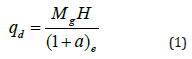
Where M is the hammer mass, H is its falling height, a is the ratio of masses (a=P/M, the rod-system penetrated mass, P, over the hammer mass, M), e is the penetration of the rod after impact and g=9.8m/s2 [19]. Core samples and PANDA tests points are presented in Figure 5.
Results and Discussion
Monitoring results
The results of the strain measurements during the remediation process are shown in Figure 6 along with the rolling mean (moving average) and standard deviations. The four FOS show all a general negative trend which is characterized by a compression in the monitored elements. This means that the cracks, especially the largest crack (FOS 4) are being closed during the injection operations expect the FOS 2 which shows a positive trend i.e. a traction in the monitored element.
Figure 6: Results obtained from the optical fiber sensors at 4 different position of the building (μm).

Field experiments results
Results of the laboratory experiments on the samples before and after the injection showed that the material is not always homogenous, and samples may not be affected by the injection during the remediation process. Furthermore, results of the insitu dynamic resistance of the soil are presented in Figure 7. It can be generally observed that there is an improvement of the tip resistance in the soil close to the FOS 1 and FOS 4 sensors (P1 and P8). These sensors also showed a negative trend (closing of the cracks). It should be mentioned that in other test points (P3 and P8), the tip resistance has not changed or just slightly improved after remediation.
Figure 7: Results of in-situ PANDA tests before and after the injection process.

Analysis
A. FOS 1: the injection under the monitored wall with
sensor 1, showed a stable behavior of the structure during
the injection. The wall was slightly compressed (0.02mm)
during the injection and when the injection was completed, it
went back to its initial state. The results of the PANDA test at
this point (P1/P1*) showed a significant improvement of the
dynamic resistance in the first 60cm of the soil profile but a
decrease from 60cm to 2m depth. It is generally concluded that
the wall at this point was stable and the soil has been improved
in the first meter.
B. FOS 2: shows mainly a tension of the optical fiber from
the beginning of the injection. 35kg of resin was injected at this
point, but the results of the optical fiber measurements did
not show any compression at the beginning meaning that the
resin was not being distributed at the considered spot under
the footings. It was then observed that the resin was diffused
under the slab instead. However, a compression phase and a
rising up of the wall is captured by the sensor 2 at the end of
the monitoring period. The injection was stopped right after
the compression phase was observed. The results of the PANDA
test at this point (P5/P5*) did not show any changes in the soil
profile as expected because the resin was not distributed in the
considered spot.
C. FOS 3: shows that the injection under the footing at
this point has led to an overall rise in the structure resulting
in a stable response of the optical fiber sensor. 25 Kg of resin
were injected under this wall without causing any damage.
Results of the PANDA test in the vicinity of this point (P3/P3*)
show a slight improvement in the top layer of the profile and
almost no change in the dynamic resistance after the injection
phase. It can be derived that the complementary PANDA test
after the injection (P3*) was not able to capture the effects of
the injection but the stability of the structure was confirmed
with the optical fiber sensor. Complementary in-situ tests can
confirm the improvements of the soil mechanical properties at
this point.
D. FOS 4: shows the results of the crack openings installed
on the largest external crack and potentially the most damaged
part of the building. This unique curve shows that the resin
injection under the foundation soil resulted in a closure of
the crack in a range of 0.5 mm. 27 kg of resin were injected
at this point and the results from the PANDA test carried out
before and after the injection phase (P8/P8*) show significant
improvements in the soil profile.
Conclusion
A damaged masonry structure due to the presence of clayey soils was monitored by FOS during the remediation process. The soil laboratory investigations before and after the injection phase could not give a reasonable argument of the injection effect on the samples’ physical characteristics. The in-situ improvements could not be completely verified by laboratory investigations however, the in-situ geotechnical investigation showed much more coherent results. The use of FOS and the in situ dynamic penetrometer test simultaneously is a combined monitoring technique that can give show the evolution of generated strains along the improvements of the soil mechanical parameters. The FOS 4 is a unique example in which the crack is being closed as the injection is taking place. It can be concluded that the injection can continue until the sensors are showing stable strain values and until a traction in the monitored elements has not taken place. If sensors are installed on cracks, the injection should be stopped after a complete compression. This study revealed the possible applications of FOS on masonry structures. It should not be neglected that further geotechnical study both in laboratory and field scale could give better understanding of the resin injection path into the soil.
References
- Taheri S (2019) A review on five key sensors for monitoring of concrete structures. Construction and Building Materials. 204: 492-509.
- Khandelwal P (2013) Optical fiber sensors: Classification & applications. IJLTEMAS 2(7).
- Leung CKY, Wan KT, Inaudi D, Bao X, Habel W, et al. (2015) Review: optical fiber sensors for civil engineering applications. Mater Struct 48: 871-906.
- Jahangir E (2011) Soil-structure interaction phenomena with regard to the shrinkage-swelling hazard for the assessment of the vulnerability of structures. Solid mechanics. National Polytechnic Institute of Lorraine-INPL.
- Adem HH, Vanapalli SK (2015) Soil-environment interactions modeling for expansive soils. Environmental Geotechnics 3(3): 178-187.
- Assadollahi H, Sharma LK, Dinh AQ, Tharaud B (2018) Monitoring the efficiency of polyurethane resin injection for foundation remediation in damaged residential buildings exposed to expansive clays. In International Congress and Exhibition "Sustainable Civil Infrastructures: Innovative Infrastructure Geotechnology", pp. 148-157.
- Assadollahi H, Nowamooz H (2020a) Long-term analysis of the shrinkage and swelling of clayey soils in a climate change context by numerical modelling and field monitoring. Computers & Geotechnics, Volume 127.
- Assadollahi H, Nowamooz H (2020b) Long-term behaviour of natural clays in a building foundation under climate change scenarios. Environ Geotech.
- Assadollahi H (2019) The impact of climatic events and drought on the shrinkage and swelling phenomenon of clayey soils interacting with constructions. PhD Thesis. Universite de Strasbourg, France.
- Fernandes M, Denis A, Fabre R, Lataste JF, Chretien M (2015) In situ study of the shrinkage of a clay soil cover over several cycles of drought-rewetting. Engineering Geology 192: 63-75.
- Hemmati S, Gatmiri B, Cui YJ, Vincent M (2012) Thermo-hydro-mechanical modelling of soil settlements induced by soil-vegetation-atmosphere interactions. Engineering Geology 139-140: 1-16.
- Nowamooz H, Assadollahi H (2019) Investigation of in situ soil-atmosphere interaction with a hydro-thermal simulation approach: application to an instrumented site. Eur J Environ Civ Eng.
- Buzzi O, Fityus S, Sasaki Y, Sloan S (2008) Structure and properties of expanding polyurethane foam in the context of foundation remediation in expansive soil. Mech Mater 40(12): 1012-1021.
- Buzzi O, Fityus S, Sloan S (2010) Use of expanding polyurethane resin to remediate expansive soil foundations. Can Geotech J 47(6): 623-634.
- Valentino R, Romeo E, Stevanoni D (2014) An experimental study on the mechanical behaviour of two polyurethane resins used for geotechnical applications. Mech Mater 71: 101-113.
- Svaldi AD, Favaretti M, Pasquetto A, Vinco G (2005) Analytical modelling of the soil improvement by injections of high expansion pressure resin. Bull Angew Geol 10(2): 71-81.
- Santarato G, Ranieri G, Occhi M, Morelli G, Fischanger F, et al. (2011) Three-dimensional electrical resistivity tomography to control the injection of expanding resins for the treatment and stabilization of foundation soils. Eng Geol 119(1–2): 18-30.
- Nowamooz H (2016) Resin injection in clays with high plasticity. CR Mecanique 344(11-12): 797-806.
- Fairhurst C (1961) Wave mechanics of percussive drilling. Mine Quarry Eng, pp. 169-178.
© 2021 Hossein Assadollahi. This is an open access article distributed under the terms of the Creative Commons Attribution License , which permits unrestricted use, distribution, and build upon your work non-commercially.
Editor In Chief


.jpg)


Signup for Newsletter

Quick Links
 Editorial Board Registrations
 Submit your Article
 Refer a Friend
 Advertise With Us
Our Recent Edition

.jpg)


Top Editors


.jpg)


.bmp)
.jpg)
.png)
.jpg)


.jpg)


.png)

.png)


.png)


Financial Support

Sponsors

Latest e-Books

Latest Video

 a Creative Commons Attribution 4.0 International License. Based on a work at www.crimsonpublishers.com.
Best viewed in
a Creative Commons Attribution 4.0 International License. Based on a work at www.crimsonpublishers.com.
Best viewed in