
- About Us
- Information
-

The Author ensures that the research has been conducted responsibly and ethically with adherence to all relevant regulations. read more..
- For Authors
- For Reviewer
- Manuscript Guidelines
- Membership
- Publication Ethics
-
- Journals
- Reprints
- e-Books
- Videos
- Policies
- Contact Us
 COVID-19
- Submissions


Full Text
Advancements in Civil Engineering & Technology
An Undergraduate Study of a Fluids Time-To- Drainage Device
Hasan Ukra, Anna Gavalyan, Ali Alkaribani, Trisheendran S Tenakaran, Ahmed Aljsaar, Danah Abdulkareem, Abdallah Alsaidy, Emanuel De Los Santos, Ali F Almutairi, David Boyajian* and Tadeh Zirakian
Department of Civil Engineering and Construction Management, USA
*Corresponding author: David Boyajian, Department of Civil Engineering and Construction Management, USA
Submission: February 20, 2019;Published: March 06, 2019

ISSN: 2639-0574 Volume3 Issue1
Abstract
In this educational research study, a group of undergraduate students, under the supervision of Dr Boyajian and Dr Zirakian from California State University Northridge, introduce a designed fluid time-to-drainage model as part of the Senior Design undergraduate course. The model was chosen to be a time-to-drainage device due to the high resistance against pressure as well as being impervious to water. The main objective of this project is to experimentally examine the effects of using sharp and round edge orifices under different values of pressure, on the water flow rate and to inspire minority and international students in engineering to learn the effects of this pressure change and using different orifice geometries, on the fluid flow properties. This research endeavour is hoped to serve as a model for future generations of engineering students to better visualize difficult Fluid Mechanics concepts and thus enhance their overall comprehension of such important material..
Keywords: Educational research; Minority students; Students in engineering; Sharp/Round orifice; Time-To-Drainage
Introduction
Generally, fluid drainage systems have important applications in the Engineering field and more specifically in the Water Resources area of Civil Engineering, whereas designs of storm drain inlet/outlet, sewage systems and pure water delivery systems, as well as other main pipeline designs. The flow of fluids is an important parameter in the design of largescale hydraulic projects and a further study of the effects on the behaviour is necessary. For simplicity, a small water drainage device was chosen to be like that of a water clock mechanism in draining the water out from small orifices. This device was built to show the influence of changing the orifices geometry on the flow when discharging the water from one closed system to another. To utilize such device in educational purposes and to obtain accurate results, students were required to study fluid mechanics in engineering courses to understand the behaviour of fluids and the effects of forces on fluid motion.
In ancient times, as early as the 4th century B.C., different forms of water drainage devices were invented such as water clocks [1,2]. According to Mills [3], it was found that the outflow of water could not be maintained on a constant rate due to the viscosity of water being higher than the required pressure for the water to flow out from the container. In relation to this research study/project, according to Flachskampf et al. [4], Goikoetxea et al. [5] and Penney et al. [6], the orifice geometry that the water flows out from within a system, played a significant role in changing the property of the flow rate. Additionally, the change in pressure was found to be directly proportional to the flow rate of fluids from a closed system [7].?
In relation to what is discovered today throughout recent studies related to water drainage systems, this research focuses on accurate measurements of the outflow rate of water with respect to time. The outflow of water is influenced by several factors, including the surface pressure of water within the system, the orifice size, and the geometry. The essential idea of this project is to design and construct a testing model where water can be discharged from a closed system/container into another, while keeping a constant pressure inside the container to maintain a constant outflow rate. After measuring the time frame during which the water is completely discharged from the system, then the value as a standard period of time for the timekeeping device is being used. For simplicity, a sharp orifice and a round edge orifice are used for comparison and to confirm the rate of discharge. The main objective of this project is to construct an educational water drainage model that can help minority and international students in engineering to visually learn the fundamentals of fluid mechanics and how those concepts can be implemented in real-life application.
Design of the physical model
Materials: The tanks were made of clear extruded acrylic sheets. The project required 3 OPTIX 0.22“x 18“x 24“clear acrylic sheets. An epoxy glue (3000 psi) sealed the tanks. Wood glue sealed the wood frame. The project also required 4 air valves (12 1⁄2“ x 1.75-2.1“), silicone sealant, 1⁄4“ poly tubing, a straight needle valve (1⁄4“ x 1⁄4“), 8 wood nails (1/16“) , and wood frame: 7 1⁄2“ x 15“ lumber board, 3 lumber boards (7 1⁄2“ x 7“), and a cordless drill (drill bits used: 3⁄8“ 1/16“, and 1⁄3“). To finalize the list, the members used 12V/120V car air inflator to pressurize the tanks. Some of the materials used during construction are shown in Figure 1.
Figure 1:Materials used in construction of the model.

Construction
Figure 2:Assembled cubicle tanks with sharp and round edged orifice

The acrylic sheets were cut to the dimensions that were assigned through the design of the project. 16 sheets were cut to assemble a total number of four tanks. Strong epoxy glue was used to seal the tanks as shown in Figure 2. The idea was to have two tanks with sharp edges and two tanks with round edge orifices ready for the experiment. After drilling some holes, the valves were plugged. Making an opening for a tube in each tank was also mandatory. The upper sheet of each tank was also glued to prevent any leakage. The tanks were positioned inside the wood frame to fit the idea of the project. At the end, the air inflator was used to constantly pressurize the tanks.
Geometrical and material details
A frame was designed to hold two tanks separately after having the accurate measurement for the tanks. The design of the frame was simplified to an E-shape (Figure 3) to hold the tanks one on the top of the other. Engineering software “Rhinoceros” was used to create a frame in a two-dimensional design. Based on the proposed dimensions, the frame was assembled using wood plates and a driller to hold each wood plate together. The wood plates were used to give a natural look for the design.
Figure 3:Dimensions of the E-shaped constructed wood frame.

Experimental Procedure
All the dimensions of the experimental apparatus are shown in Figure 4 along with an image of the actual model as shown in Figure 5. The apparatus consisted of four 6“cube sealed acrylic tanks, four schrader valves, ¼ “poly tubing, a wooden frame and a car inflator. Two of the four tanks were drilled to have a round orifice while the other two tanks were drilled to have a sharp orifice. Holes were drilled in each tank to place a schrader valve and an opening to refill water into the tank. The schrader valve was used to connect the tank with the car air inflator pump. A ¼ “poly tube was connected between the orifices of two similar types of tanks. First, one of the sharp tanks was filled with water until the water reached 4“high. Both sharp orifice tanks were placed on the wooden frame. The experiment was conducted at atmospheric pressure by allowing the atmospheric pressure to enter via the water refilling hole. The time measured for the whole 4“of water to be transferred to the second tank was being recorded with a stopwatch (Extech with accuracy of ±3 seconds per day) for the experimental time of the sharp orifice at atmospheric pressure.
Figure 4:Details of the acrylic cubicle tanks.

Figure 5:Physical prototype of the model.

The same procedure was repeated for the round orifice tanks, and the experimental value for time for round orifice at atmospheric pressure was recorded. The experiment for both the sharp and round type of orifices were then being tested at different gauge pressures, at 1psig, 2psig, 3psig, 4psig and 5psig. The pump was connected to the schrader valve to pressurize the tank. During the measurement run, the pump was set to maintain the desired internal pressure of the tank at a constant value. Time taken for both types of tanks at respective pressures was recorded. Using the continuity equation (Eq. (1)), the theoretical values for the time taken for both types of orifices to flow out 4 inches of water at atmospheric and respective pressures were calculated. The experimental and theoretical time taken for each orifice type and each pressure condition was graphed and compared. The error between the theoretical and experimental values were calculated.
Theoretical Predictions and Test Results
The continuity equation (Eq. (1)) was used to calculate the theoretical values of the time of discharging the water from one tank into the other under atmospheric pressure, as well as different values of gauge pressure, for sharp and round edged orifices. As shown below in equations (Eq. (1), (2), and (3)), the equation was rearranged by integrating both sides to solve for the time as the target unknown:
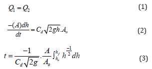
where Q is the water flowrate, A is the area of the tank, Ao is the area of the opening, Cd is the hydraulic coefficient of the orifice, g is the gravitational acceleration, hf is the height of the water surface, ho is the initial height (bottom of the orifice), and P is the atmospheric pressure. Table 1 and 2 indicate the experimentally obtained and theoretically calculated data for sharp and round edge orifice. Atmospheric, different values of gauge pressure and the recorded time are listed in the tables. In addition, the experimental and theoretical results were compared, and percentage of error was calculated.
As shown in Figure 6 and 7, Microsoft Excel spreadsheet was used to construct pressure-time theoretical and experimental curves for sharp and round edge orifices, respectively. The two curves were constructed using a second order polynomial trendline, which was generated by Microsoft Excel. The trendline was then computed forming two different equations, which were compared to find the relative percentage of errors between the theoretical and experimental values. On the other hand, the coefficient of determination, R2 of both curves in Figure 6 and 7 presented the correlation in between the independent variables y and the dependent variables x on the plot. The idea of having the R2 value is to represent a ratio of the data points that were plotted to the actual trendline of the curve. Through Microsoft Excel, R2 values were calculated using the obtained data, and values came out to be very close to 1 (100%) and that confirmed the best-fitting trendline to the data that was used in both sharp and round edge orifices’ systems.
Figure 6:Pressure-Time theoretical and experimental constructed curves for sharp edge orifice.

Figure 7:Pressure-Time theoretical and experimental constructed curves for round edge orifice.

As previously shown in Table 1 and 2, various values of pressure and the corresponding outcome of both theoretical and experimental time values for the sharp and round edge orifices were listed. The theoretical values were the resultant values of time that were derived from the continuity equation (Eq. (3)). As shown in Table 1, the highest and lowest percentage of errors between both the experimental and theoretical values for the sharp edge were 19.4% at a pressure of 1psig and 10.2% at 5psig. Meanwhile, Table 2 performed the highest and lowest errors at 21.3% at 1psig and 4.0% at 3psig respectively for round edged orifice. Values at 1psig, in both sharp and round edge orifices’ systems, came out to be higher, around 19.4% and 21.3% for the sharp and round edge orifices. Those high percentage errors were mainly due to the non-accuracy of the air inflator when providing such low-pressure values (e. i. 1 psi), which concluded that as pressure increased, there found to be a noticeable decrease in the discrepancy/percent error. Overall, the experiment was found to be valid when comparing the two models using the different pressure values, as the sharp edge orifice model generally took a longer period to completely discharge the water out from one tank to the other, than the round edge orifice under any given pressure, which confirmed the two main objectives of the project.
Table 1:Experimental and theoretical results for sharp edge orifice and calculated discrepancy.

Table 2:Experimental and theoretical results for round edge orifice and calculated discrepancy.

Educational Objectives
From this educational research, students managed to extend their knowledge in fluid mechanics and hydraulics by solving realworld problems. The students, from different genders, ethnicities, religions and backgrounds, were able to work in one group to perform the experiment successfully. The fabrication process of the waterproof and airtight tanks helped the students in overcoming many real-world problems faced in making low cost pressurized tanks. The students from different life experiences, brainstormed together in a group to find the best solutions in every problem faced. For an example, the students experimented different types of cohesive glues to determine the best material to be used in fabricating the pressurized tanks. The high diversity in the group managed the students to share vast knowledge and personal experiences during the performed experiment. Despite having members from different races and religions, the students worked in a harmonious condition and learned to respect one another. Hence, this research educated the students on how to work in a highly diversified group while eliminating the idea of racial discrimination in the mindset of all students. In the era where the United Nations (UN) is promoting The International Convention on the Elimination of All Forms of Racial Discrimination (ICERD) globally, it is important for educational institutes to encourage students to work in a highly diverse group environment.
As a team, the students managed to cultivate their personal skills and professional ethics by dedicating their time and effort into the project. The positive outcome of the conducted experiment was a great evaluation for the students’ performances in the experiment. The knowledge and experiences gained by the students in the experiment were very vital in pursuing their careers as future engineers. By the end of this module, students were able to understand and apply the fundamentals and the principles of hydraulics in their related field of engineering. After completing the research paper, the students were well-experienced in writing journals and being more passionate in writing more professional journals for educational purposes.
Conclusion
In this cognitive engineering learning process, students were able to implement the knowledge on hydrostatics and fluid mechanics gained from the courses during their undergraduate studies to design, construct and examine the water time-todrainage model that was discussed earlier in this educational research project. The design included four cubical tanks having every two tanks connected by a single tube. The first two tanks had sharp orifices, while the other two had round orifices. Furthermore, the two-dimensional drawing done on engineering software “Rhinoceros” showed the geometric shape of the designed model and all the measurements. The tables, graphs, calculations and obtained results in this study showed the difference between the two orifices and clarified how different shapes of orifices can change the results of the design. In taking the measurements, theoretical and experimental approaches gave relatively close results. To be more accurate, the percent error between the experimental and the theoretical for the sharp orifice was calculated to be 19.4% at a pressure of 1psig and 10.2% at 5psig, respectively. Meanwhile, the percent error for the round orifice was calculated to be 21.3% at 1psig and 4.0% at 3psig.
Acknowledgment
The authors of this article would like to show gratitude to Dr David Boyajian and Dr Tadeh Zirakian, Professors of Civil Engineering in the Department of Civil Engineering and Construction Management at California State University, Northridge, CA, USA, for sharing their pearls of wisdom during the course of this research.
References
- Frank FA, Weyman AE, Guerrero JL, Thomas JD (1990) Influence of orifice geometry and flow rate on effective valve area: An in vitro study. Journal of the American College of Cardiology 15(5): 1173-1180.
- Goikoetxea E, Alberdi A, Suarez A, Arleo F, Lamikiz A (2011) Numerical simulation of water jet quality for different orifice geometries. DAAAM International scientific book, pp. 513-526.
- McNown John S (1976) When time flowed the story of the clepsydra. La Houille Blanche 5: 347-353.
- Lindeburg, Michael R (2018) PE civil reference manual. 16th edn, Professional Publications, Inc, USA.
- Mills AA (1982) Newton’s water clocks and the fluid mechanics of clepsydrae. Notes and Records of the Royal Society of London 37(1): 35- 61.
- Major FG (2007) The quantum beat: principles and applications of atomic clocks. Springer, New York, USA.
- William PR, Servoss SL, Hestekin CN, Clausen EC (2016) A simple sharp-edged orifice demonstration for the fluid mechanics classroom. American Society for Engineering Education.
- Efstratios T, Katsiotis M, Manimanis V, Mantarakis P (2010) The large built water clock of Amphiaraeion. Mediterranean Archaeology and Archaeometry 10(1): 159-167.
© 2019 David Boyajian. This is an open access article distributed under the terms of the Creative Commons Attribution License , which permits unrestricted use, distribution, and build upon your work non-commercially.
Editor In Chief


.jpg)


Signup for Newsletter

Quick Links
 Editorial Board Registrations
 Submit your Article
 Refer a Friend
 Advertise With Us
Our Recent Edition

.jpg)


Top Editors


.jpg)


.bmp)
.jpg)
.png)
.jpg)


.jpg)


.png)

.png)


.png)


Financial Support

Sponsors

Latest e-Books

Latest Video

 a Creative Commons Attribution 4.0 International License. Based on a work at www.crimsonpublishers.com.
Best viewed in
a Creative Commons Attribution 4.0 International License. Based on a work at www.crimsonpublishers.com.
Best viewed in