- Submissions

Full Text
Advancements in Civil Engineering & Technology
Designing a Two‐Floor Urban Traffic Tunnel by Using NATM Tunneling Method in Tehran Alluvium with Shallow Overburden under Modares Highway
Aliakbar Golshani1*, Baharak Alinejad2 and Sina Majidian3
1 Tarbiat Modares University, Iran
2 Tunnel Design engineer in geotechnical department of P.O.R engineering Consulting group, Iran
3 Geotechnical Engineering, Iran
*Corresponding author: Aliakbar Golshani, Faculty of Civil and Environmental Engineering, Tarbiat Modares University, Iran
Submission: April 11, 2018;Published: May 10, 2018

ISSN: 2639-0574 Volume1 Issue2
Abstract
In this paper construction of urban traffic tunnel in disturbed soil stratum based on New Austrian Tunneling Method (NATM) has been investigated. As a case study, Modares tunnel which is a part of Arash‐Esfandiar‐Niyayesh Project has been considered. This tunnel has been designed to connect and reduce the traffic volume between Modares highway and Niyayesh Highway in north of Tehran‐Iran. The ellipsoid shape of this tunnel, with two floors and the shallow depth, and its location in disturbed soil stratum, the large section of tunnel and the existence of embedded cannels makes Modares tunnel to be one of the sensitive parts of project. Dimensions of tunnel Excavation is 12.18m in width and 13m in height, with initial lining thickness of 35cm. Initial lining consists of 6, ∅32 micro‐piles, and 4, IBO R32S nails. The shotcrete of class C25 has been applied in initial support. Since Modares tunnel underpasses one of the most important main roads of Tehran, so the settlement amount has to be restricted. On the other hand, because the tunnel has been constructed in a shallow depth and considering the large dimensions of the section, we may encounter high ground settlements. To avoid these amounts of settlements, we use fore‐poling system to improve disturbed soil properties on top of tunnel, and micro‐ piles and nails for decreasing the vertical displacement amount. In this article we are intend to compare the results of the finite element model to monitoring results during construction and after that. Also we compare two numerical design alternatives for this tunnel from settlement perspective.
Keywords: NATM; Settlement; Fore‐poling; Micro‐pile; Nail support; Micropiles; chainage
Introduction
figure 1:Arash-Esfandiar-Niyayesh project location and accessibility.
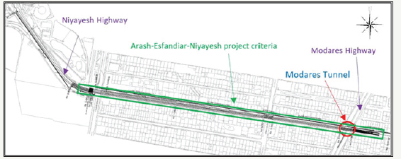
Modares Tunnel is a part of Arash‐Esfandiar‐Niyayesh Project. This project has been designed to reduce the traffic and connect Modares Highway to Niyayesh Highway with a length of 1.7 kilometres from east to west. The Modares tunnel is located at the eastern part of the project, as shown in Figure 1. Modares Tunnel is a two‐floor tunnel in a disturbed soil alluvium with a shallow depth. This tunnel crosses beneath Modares Highway which is one of the main Highways of Tehran cities. Accordingly vertical displacements are at most important. This tunnel contains two floors, the top floor is a west to east path from west Arash Avenue to east Arash Avenue (two streets which ends to Modares highway) and the bottom floor is an east to west path and also starting of the main tunnel of Arash‐ Esfandiar‐Niyayesh project. The tunnel is designed with a shallow depth of 3 meters. The large dimensions of the section, along with shallow depth of tunnel and its location in disturbed soil cause this part of tunnel to be one of sensible parts of project.
Since the settlement of the tunnel is an important issue, the fore‐poling system has been considered. Spiles or fore‐poles are used to provide a temporary protection and avoid collapse before excavation in soft or disturbed soils. As the Modares highway is one of the major roads of Tehran city with a high traffic flow, and can’t be interrupted, the improvement of the disturbed soil is necessary. Therefore 60 fore‐poles with grout average volume of 100 liters and specific weight of 16.5 KN/m2and tensile strength of 15 kg/cm2 has been considered.
In this article we are about to consider two design simulations, and study their displacements. As the settlement of this part of project is so important, we have to restrict the vertical displacements on ground surface to 1inch. Thus the maximum vertical displacement in total and on the ground surface, of the two design alternatives has been compared and then the approved model’s displacement results will be compared with monitoring results. The first numerical model is consists of an ellipsoid shape tunnel, the second model is the same tunnel with 6 ∅32 micropiles and 4 IBO R32S nails (Figure 2).
figure 2:a) The position of 2 floor modares tunnel next to modares highway b) The arrangement of forepoles.
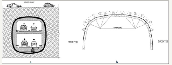
figure 3:Modares tunnel initial lining a) inside view b) outside view.
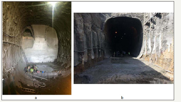
The excavation view from inside and outside of tunnel has been represented in Figure 3. The position of nails on tunnel’s wall is visible in Figure 3a, while the fore poling system locating on top of tunnel roof is recognizable in Figure 3b.
Methodology
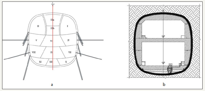
Figure 4 the construction stages of tunnel demonstrated in Figure4a. In both numerical models the construction stages are the same with just one difference, that in the first model there is no nails and micro‐piles installation, while in the second model, nails and micro‐piles have been installed in their predetermined places after the initial lining of that specific stage has been constructed. The final lining of Modares tunnel has been represented in Figure 4b.
As mentioned before, for designing Modares tunnel we tried to restrict vertical displacements at the ground surface to 1 inch (2.5cm). Thus, for initial lining 6 ∅32 micropiles and 4 IBO R32S nails, and the specified concrete strength of C25 has been used
figure 4:Two-floor Modares tunnel cross section a) excavation stages, with the position of micro-piles and nails for the initial lining, b) Final lining.
Numerical Modeling
The simulation comprises finite element method. The twodimensional finite element software Plaxis V8.5 is used for numerical analysis. Design calculations are based on two FHWA publications, one is soil nail walls‐reference manual (FHWA‐NHI‐14‐007) and the other is technical manual for design and construction of road tunnels and civil elements (FHWA‐NHI‐10‐034). As mentioned before, in this article we compared two design alternatives for initial lining of Modares tunnel. Finally, the numerical results will compare with the monitoring outcome. The difference between two models is as below:
First model
The initial lining contains a layer of shotcrete with thickness of 35cm and a layer of fore‐poling system
Second model
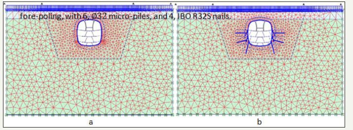
The initial lining contains a layer of shotcrete with thickness of 35cm and a layer of fore‐poling, with 6, ∅32 micro‐piles, and 4, IBO R32S nails (Figure 5).
figure 5:Two-floor Modares tunnel numerical simulation a) First model, b) Second model.
Material Properties and Design Parameters
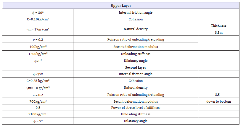
For each simulation 15 node elements have been used. The initial lining properties are represented in Table 1. The soil constitutive model (material behavior) is considered as hardening soil. Soil layer’s parameters have been indicated in Table 2.
Table 1:Initial lining parameters.

Table 2: soil layer’s geotechnical parameters.
Monitoring Procedure
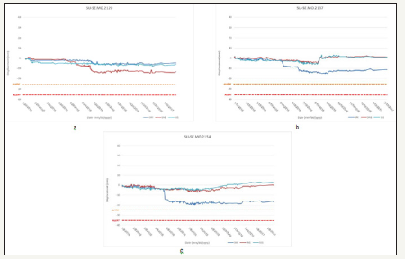
The monitoring elements such as Settlement, Geodetic, and Convergence pins have been used for detecting monitoring data’s in this project. The position of settlement pins for Modares tunnel has been demonstrated in Figure 6. The monitoring results for 3 chainages, in three settlement points of middle, north and south position of each chainage have been shown in Figure 7.
figure 6:The position of monitoring tools in Modares tunnel.
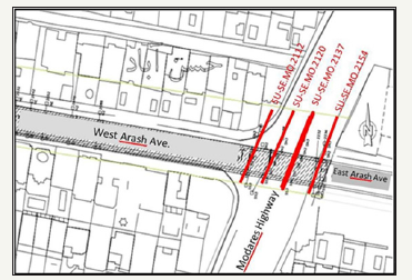
figure 7:Monitoring results for three settlement points in three chainages, a) Km2120, b) Km2137, c) Km2154.
Results
Modares tunnel is a shallow two‐floor tunnel with a large section, underpasses one of most significant main roads of the capital of Iran, Tehran. In order to avoid any disorders in traffic flow of Modares highway the surface vertical displacements have been restricted to 1 inch in design. The maximum vertical displacement in both models as shown in Figure 8 occurred in the top area of the tunnel. The maximum amount of vertical displacement obtained from the first model is 4.19cm, and from the second model is 2.91cm as shown in Figure 8. As a result 6, ∅32 micro‐piles, and 4, IBO R32S nails were used in order to reduce the vertical displacement in the second model. The maximum vertical displacement in ground surface for the first model is 3.89cm, while for the second model is 2.69cm which has been illustrated in Figure 9. According to the displacement results the second model is in the allowable displacement range. In this part we tend to compare monitoring results with corresponding numerical results of the second model. The comparison of monitoring and analysis results demonstrated in Figure 10. The different stages of excavation and initial lining construction have been determined in Figure 10.
figure 8:Maximum Vertical displacement distributions for two design alternatives of modares tunnel.
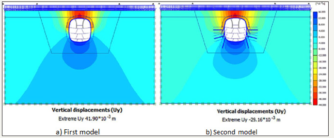
figure 9:Vertical displacement occurred on ground surface obtained from the second model.

figure 10:Surface settlement diagram based on monitoring versus numerical data.
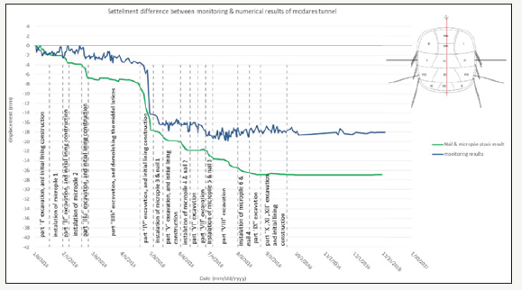
Based on the surface settlement diagram (Figure 10), it can be concluded that, the settlement ratio is increasing sharply in excavation stages, on the other hand, installing micro‐piles and nails reduce the ratio till the beginning of next excavation stage. The difference between monitoring results and numerical results in the last stages of initial lining is due to fore‐poling system performance on top of tunnel, which improves the disturbed soil properties. Also a part of this consequence may be the result of that; the soil properties obtained from geotechnical studies are not exactly accurate. So there is a need for back analysis to estimate the precise soil parameters [1-6].
References
- Hung JC, Monsee J, Nasri M, Wisniewski J (2009) Technical manual for design and construction of road tunnels civil elements (FHWA‐NHI‐10‐ 034). Federal Highway Administration, Washington, USA, pp. 1-172.
- Carlos AL, Helen R, Jesús E, Andrew B, Allen C, et al. (2005) Soil Nail Walls (FHWA‐NHI‐14‐007). Federal Highway Administration, Washington, USA, pp. 1-425.
- Paul JS, Burak T, Tom A, Paul G, James K (2005) Micro‐pile Design and Construction (FHWA‐NHI‐05‐039). Federal Highway Administration, Washington, USA, pp. 1-426.
- Brinkgreve RBJ, Broere W, Waterman, D (2002) Reference manual of PLAXIS 2D‐ Version 8, Netherland. AA Balkema Publishers, England.
- The British Tunnel Society and Institution of Civil Engineers (2004) Tunnel Lining Design Guide. London, Thomas Telford Ltd, London, England p. 200.
- ACI Commmittee 318 (1992) Building code requirement for reinforced concrete‐ ACI committee 318‐89 and commentary‐ ACI committee 318R‐89. American concrete institute, USA.
- Schanze T, Vermeer PA, Bonnier PG (1999) The hardening soil model: formulation and verification. Beyond 2000 in Geotechnical Geotechnics, ten years of PLAXIS, Balkema, Rotterdam, ISBN 90 5809 040X, Germany, p. 16.
© 2018 Aliakbar Golshani. This is an open access article distributed under the terms of the Creative Commons Attribution License , which permits unrestricted use, distribution, and build upon your work non-commercially.
 a Creative Commons Attribution 4.0 International License. Based on a work at www.crimsonpublishers.com.
Best viewed in


.jpg)


 Editorial Board Registrations
 Submit your Article
 Refer a Friend
 Advertise With Us
.jpg)


.jpg)


.bmp)
.jpg)
.png)
.jpg)


.jpg)


.png)

.png)


.png)


