- Submissions

Full Text
Trends in Textile Engineering & Fashion Technology
Machine Type Innovation Trend and SWOT Analysis of Filament Winding: A Mini Review
Quanjin Ma1,2*, MRM Rejab1,2 and MS Idris1
1Structural Performance Materials Engineering (SUPREME) Focus Group, Faculty of Mechanical & Automotive Engineering Technology, Universiti Malaysia Pahang, Malaysia
2School of Mechanical Engineering, Ningxia University, China
*Corresponding author:Quanjin Ma, Structural Performance Materials Engineering (SUPREME) Focus Group, Faculty of Mechanical & Automotive Engineering Technology, Universiti Malaysia Pahang, 26600 Pekan, Pahang, Malaysia
Submission: November 01, 2022; Published: November 18, 2022

ISSN 2578-0271 Volume 7 Issue3
Abstract
Filament winding process has increasingly developed on machine development, which brings a new era of filament winding process. This paper briefly reviews the winding machine development trends of the filament winding process, which includes a historical overview of filament winding, classification type and filament winding patterns and methods. Moreover, a SWOT (Strength, Weakness, Opportunity, and Threat) analysis of filament winding is studied. Furthermore, industrial filament winding machines on the goal post and bed types are compared and discussed.
Keywords:Filament winding; Winding pattern; Machine development
Abbreviations:RFW: Robotic Filament Winding; VARTM: Vacuum-Assisted Resin Transfer Molding; RTM: Resin Transfer Molding
Introduction
Filament winding is an automated method to fabricate composite structures/ products by winding filaments or fibers over a rotating supporting form/mandrel with controlled tension [1]. Filament winding is used to manufacture various products [2,3], such as pipes [4], drive shafts, pressure vessels [5], rocket motor cases [6] and launch tubes. Numerous filament winding machines are commonly used to produce components based on two classical axes or high axes filament winders. The filament winding process has evolved from a classical lathe-type machine towards winding with several degrees of freedom using more complex equipment in the last 20 years. With the development of this process, the filament winding machine design structure has developed to allow higher degrees of freedom for more complex mandrel shapes and winding patterns. Many control systems have been chosen to control the machine with the proper, simple, and inexpensive system [7-11]. For example, Mutasher et al. [12] have proposed a computer-generated hardware configuration for automated composite fiber with a 2-axis filament winding machine with PIC 18F452 microcontroller [12]. Moreover, Koussios et al. [13] indicated that the surface quality of the mandrel and the type of winding process considerably affected the obtained data through a CNC-controlled lathe-configured filament winding machine [13].
Moreover, Vargas et al. [14] have observed a unified approach of filament winding applied to complex shape mandrels, which has a Cartesian robot with three linear axes filament winding machine with the hollow mandrel [14]. Trinankur et al. [15] have carried out a 2-axis prototype filament winding machine with a simplified fiber winding angle and tension control system, which is controlled using a PLC control system [15]. Rejab et al. [16] have performed the 4-axis filament winding machine and modification controlled manually, in which related motors are controlled separately [16]. It is better to adopt automated control system to replace the manual operation. Misri et al. [17] have carried out the filament wind process by pulling the kenaf yarn through a resin bath using a 2-axis filament winding machine [17].
Furthermore, Abdalla et al. [8] have proposed a low-cost filament winding machine with a control system circuit, but the final fabrication specimens need to improve product quality [8]. Jian et al. [18] have provided a control system of mechatronics for the spindle drive of a winding machine, including a controller, rotating speed sensor, frequency converter, contact roller, package, and spindle driver motor. It can provide essential technology for high-speed winding machines about the core module in practical applications [18].
History overview of filament winding
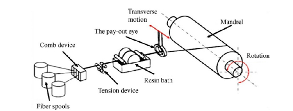
The first composite parts made by the filament winding process for the aerospace industry were fabricated in the late 1940s. Filament wound structures primarily consist of carbon fiber used in conjunction with two types of resin systems, including thermoplastic and thermosetting resins. Other factors also affect tooling material selection, which refers to a resin system, machine accuracy, type of winding machine available, delivery system, carriage system, tension system, the temperature required for the curing process, and cure time. Figure 1 illustrates the schematic diagram of the filament winding process for filament-wound composite pipes.
Figure 1:Schematic diagram of filament winding process for filament-wound composite pipes.
Filament winding technique development trend is shown in Figure 2, which evolves from a traditional 2-axis filament winding machine to a robotic filament winding (RFW) machine. Furthermore, an automated CNG tank production line is developed, providing multi-axis motions. From history overview and evolution trend, filament winding has been developed in winding machine capability and automation winding control system.
Figure 2:Filament winding machine development trends.

Classification type of filament winding machine
Filament winding process manufacturing capability and filament wound product performance mainly depends on filament winding machine axes and type [19]. Filament winding machine is categorized by their degrees of freedom with rotation and linear movement. Multi-axial filament winding is the adequate processing technology to produce composite products for medium to high internal pressures at the serial industrial level [20,21]. This manufacturing technology provides a simulation process with cylindrical vessels and domes and can use non-geodesic optimized fiber patterns in the composite laminate layers with different winding angles.
The classical filament winding machine needs the minimum
degrees of freedom with two axes: the mandrel’s rotation and
the carriage unit’s horizontal movement. The delivery eye (or the
pay-out eye) can be integrated in the horizontal carriage unit in
the two axes winder configuration. Other degrees of freedom can
be added in the additional movement of the delivery eye, like the
vertical axis, the pay-out or feed-eye rotation, and the yaw axis.
The maximum available number of axes on a filament winder are
seven [22,23], which can be commonly implemented in filament
winding industrial robots. Multi-axial filament winding systems
offer the equipment manufacturing capacity to fabricate parts with
up to two axes of motion control to produce higher-performance
and non-symmetrical products (Figure 3). Machine axes with six
numerical controlled motions are summarized in Table 1, which
can have available are
a) Spindle or mandrel (Axis A).
b) The pay-out eye or the feed-eye rotation (Axis B).
c) Yaw axis (Axis C).
d) Carriage linear motion (Axis X).
e) Cross carriage linear motion (Axis Y); Vertical linear
motion (Axis Z).
Figure 3:Axes motion definition of filament winding machine [23].
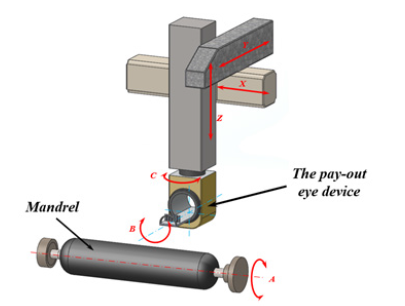
Table 1:Numerical controlled axes of filament winding machine.
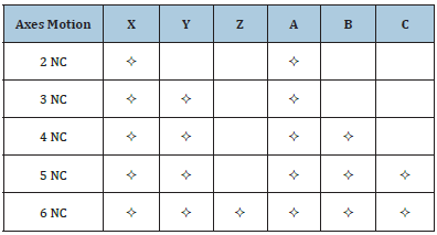
Note: X, Y, and Z are linear motions; A, B, and C are rotation motions.
Filament winding patterns and methods
The filament winding process can use a continuous length of fiber strands/rovings, which provides three winding patterns: hoop (circumferential), helical and polar winding, as shown in Figure 4. It is commonly known as hoop winding or circumferential winding. The hoop winding is a high winding angle that can approach almost 90 degrees. Each mandrel rotation can adjust the band delivery by the total bandwidth of the mandrel circumference.
Figure 4:Schematic representation of three winding patterns: (a) hoop winding, (b) helical winding, (c) polar winding [7].
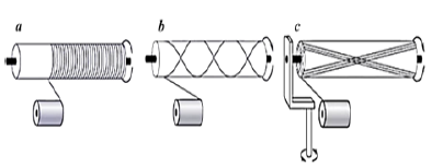
Filament winding is commonly used as helical winding, in which the mandrel rotates at constant revolutions per minute value. The fiber feed carriage (or the pay-out eye) transverses back and forth at a regulated linear speed. It can generate the desired helical winding angle. In a polar winding pattern, fiber can pass tangentially to the polar point at the end of the arm, then reverses the winding direction and passes tangentially to the opposite side of the polar point at the other end of the arm. Fibers can be wrapped from the pole point to another pole point as the mandrel arm rotates around the longitudinal axis. It is typically used to wind axial fibers on domes and end pressure vessels.
There are two different winding methods, wet and dry winding. Wet winding is fibers that can pass through the resin bath and wound on a rotating mandrel. The low-cost resin system is generally selected in commercial applications with polyester and epoxy resins. Moreover, the resin content can be affected by several specifications, such as resin viscosity, the nip-roller device, winding tension, and the number of layers. Dry winding, in which the preimpregnated fiber tows are wound on the rotation mandrel. The pre-impregnated creels provide high quality and reproducibility in resin content, uniformity, and product performance. Related parameters can be well determined in the filament winding process. Compared to wet winding, there will be an unlimited selection of fiber and resin types [24].
SWOT analysis of filament winding
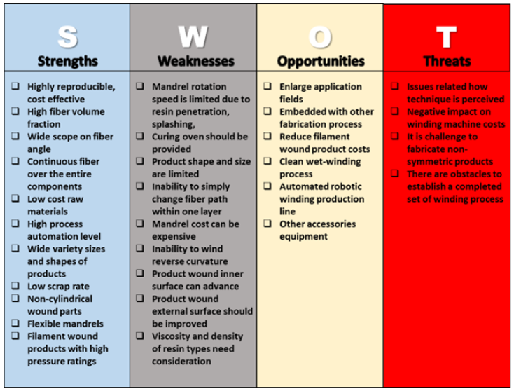
SWOT (strength, weakness, opportunity, and threat) analysis of the filament winding technique is provided in Figure 5. The strengths and weaknesses of filament winding are compared with other composite fabrication methods, such as hand layup, vacuumassisted resin transfer molding (VARTM), resin transfer molding (RTM), and compression molding [25]. Opportunities and threats of filament winding are discussed.
Figure 5:SWOT analysis of filament winding.
Goal post and bed machine type filament winding machine
It is noted that there are two main types of machines commercially used for most composite material advanced applications. One type is the overhead beam machine structure (named a goal post machine), which provides an overhead beam as the main machine foundation; another type is the bed type machine, which has a horizontal slide or packs series to move the carriage unit [26]. Figure 6 illustrates the goal post and bed machine type filament winding machine. Each machine type has its advantages and disadvantages. The advantage and disadvantages of the two machine types have summarized in Table 2.
Figure 6:Goal post and bed machine type filament winding machine: (a) multi-axis filament winding machine; (b) MAW20 MS 4/5 winding machine (Source: https://archive.mikrosam.com).

Table 2:Advantage and disadvantage comparison results between the goal post and bed machine type.

Conclusion
Filament winding has been interpreted and discussed to fabricate many different types of filament wound products based on its strengths. It is a cost-effective automated manufacturing process in composite materials in specific patterns. However, the filament winding manufacturing method is still an immature process that can be developed in the composite materials field. It has enormous potential to fabricate many different axisymmetric products. The filament winding machine mainly depends on the winding process capability, which has been developed from classical 2 axes to 6 axes filament winding machine. With the evolution of computer numerical control system and software system, filament winding software system has capitalized on the inherent flexibility of computer numerical controlled winding machines and enhanced their productivity. The robotic filament winding process has been used in filament winding with its high efficiency, high productivity, stable control system, and mature technology, which provides highfiber volume fraction filament wound products.
Acknowledgement
The authors would like to acknowledge the Faculty of Mechanical & Automotive Engineering Technology, Universiti Malaysia Pahang for funding this research: RDU1901126. This research work is strongly supported by the Structural Performance Materials Engineering (SUPREME) Focus Group.
Conflict of Interest
The authors declare that they have no known competing financial interests or personal relationships that could have appeared to influence the work reported in this paper.
References
- Quanjin M, Rejab MRM, Kaige J, Idris MS, Harith MN (2018) Filament winding technique, experiment and simulation analysis on tubular structure. IOP Conference Series: Materials Science and Engineering 342: 012029.
- Quanjin M, Salim MSA, Rajeb MRM, Bernhardi OE, Nasution AY (2020) Quasi-static crushing response of square hybrid carbon/aramid tube for automotive crash box application. Materials Today: Proceedings 27(2): 683-690.
- Quanjin M, Sahat IM, Merzuki MNM, Hassan SA, Zhang B, et al. (2019) The energy-absorbing characteristics of filament wound hybrid carbon fiber-reinforced plastic/polylactic acid tubes with different infill pattern structures. Journal of Reinforced Plastics and Composites 38(23-24): 1067-1088.
- Quanjin M, Rajeb MRM, Manoj Kumar N, Hassan SA, Idris MS (2020) Effect of winding angle on the quasi-static crushing behaviour of thin-walled carbon fibre-reinforced polymer tubes. Polymers and Polymer Composites 28(7): 462-472.
- Azeem M, Ya HH, Alam MA, Kumar M, Stabla P, et al. (2022) Application of filament winding technology in composite pressure vessels and challenges: a review. Journal of Energy Storage 49: 103468.
- Ma Q, Ge J, Rajeb MRM, Sun B, Ding Y, et al. (2021) Fabrication of the carbon fiber reinforced plastic (CFRP) cone tube through the laboratory-scale 3-axis winding machine. Materials Today: Proceedings 46(4): 1645-1651.
- Quanjin M, Rajeb MRM, Sahat IM, Amiruddin M, Bachtiar D, et al. (2018) Design of portable 3-axis filament winding machine with inexpensive control system. Journal of Mechanical Engineering and Sciences 12(1): 3479-3493.
- Abdalla F, Mutasher SA, Khalid YA, Sapuan SM, Hamouda AMS, et al. (2007) Design and fabrication of low cost filament winding machine. Materials & design 28(1): 234-239.
- Quanjin M, Rejab MRM, Idris MS, Zhang B, Merzuki MNM, et al. (2019) Wireless technology applied in 3-axis filament winding machine control system using MIT app inventor. IOP Conference Series: Materials Science and Engineering 469: 012030.
- Quanjin M, Rejab MRM, Manoj Kumar N, Idris MS (2019) Experimental assessment of the 3-axis filament winding machine performance. Results in Engineering 2: 100017.
- Ma Q, Rejab MRM, Azman O, Aleem SAA, Tung NA, et al. (2022) Development of the real-time winding angle measurement device for the laboratory-scale 3-axis winding machine. Materials Today: Proceedings.
- Mutasher S, Mir Nasiri N, Lin LC (2012) Small-scale filament winding machine for producing fiber composite products. Journal of Engineering Science and Technology 7(2): 156-168.
- Koussios S, Bergsma OK (2006) Friction experiments for filament winding applications. Journal of Thermoplastic Composite Materials 19(1): 5-34.
- Rojas EV, Chapelle D, Perreux D, Delobelle B, Thiebaud F (2014) Unified approach of filament winding applied to complex shape mandrels. Composite structures 116: 805-813.
- Hazra T, Gu J, Taheri F (2011) An innovative cost-effective approach towards tension control in automated filament winding composite manufacturing. 2011 IEEE International Conference on Mechatronics and Automation.
- Rejab M, Kadirgama K, Noor MM, Sani MSM (2008) Modification and testing of four axes filament winding machine. International Conference on Science & Technology: Application in Industry & Education pp: 12-13.
- Misri S, Sapuan SM, Leman Z, Ishak MR (2015) Torsional behaviour of filament wound kenaf yarn fibre reinforced unsaturated polyester composite hollow shafts. Materials & Design (1980-2015) 65: 953-960.
- Jian W (2007) Research on spindle drive control system of high-speed winding machine. 8th International Conference on Electronic Measurement and Instruments.
- Quanjin M, Rejab MRM, Idris MS, Bachtiar B, Siregar JP, et al. (2017) Design and optimize of 3-axis filament winding machine. IOP Conference Series: Materials Science and Engineering.
- Kang D, Kim C, Kim CG (2006) The embedment of fiber Bragg grating sensors into filament wound pressure tanks considering multiplexing. NDT & E International 39(2): 109-116.
- Velosa JC, Nunes JP, Antunes PJ, Silva JF, Marques AT (2009) Development of a new generation of filament wound composite pressure cylinders. Composites Science and Technology 69(9): 1348-1353.
- Munro M (1988) Review of manufacturing of fiber composite components by filament winding. Polymer Composites 9(5): 352-359.
- Quanjin M, Rejab MRM, Idris MS, Manoj Kumar N, Merzuki MNM (2018) Robotic filament winding technique (RFWT) in industrial application: A review of state of the art and future perspectives. Int Res J Eng Technol 5(12): 1668-1676.
- Peters ST (2011) Composite filament winding. ASM International.
- Quanjin M, Rejab MRM, Idris MS, Zhang B, Manoj Kumar N (2019) Filament winding technique: SWOT analysis and applied favorable factors. SCIREA Journal of Mechanical Engineering 3(1): 1-25.
- Wang R, Jiao W, Liu W, Yang F, He X (2011) Slippage coefficient measurement for non-geodesic filament-winding process. Composites Part A: Applied Science and Manufacturing 42(3): 303-309.
© 2022 Quanjin Ma. This is an open access article distributed under the terms of the Creative Commons Attribution License , which permits unrestricted use, distribution, and build upon your work non-commercially.
 a Creative Commons Attribution 4.0 International License. Based on a work at www.crimsonpublishers.com.
Best viewed in


.jpg)


 Editorial Board Registrations
 Submit your Article
 Refer a Friend
 Advertise With Us
.jpg)


.jpg)


.bmp)
.jpg)
.png)
.jpg)


.jpg)


.png)

.png)


.png)


