
- About Us
- Information
-

The Author ensures that the research has been conducted responsibly and ethically with adherence to all relevant regulations. read more..
- For Authors
- For Reviewer
- Manuscript Guidelines
- Membership
- Publication Ethics
-
- Journals
- Reprints
- e-Books
- Videos
- Policies
- Contact Us
 COVID-19
- Submissions


Full Text
Trends in Textile Engineering & Fashion Technology
Mathematical Approach for the Prediction of Compression Pressure
Hafiz Faisal Siddique*
Technical University of Liberec, Clothing Technology, Czech Republic
*Corresponding author: Hafiz Faisal Siddique, Technical University of Liberec, Clothing Technology, Liberec, Czech Republic
Submission: February 02, 2022; Published: March 03, 2022

ISSN 2578-0271 Volume 6 Issue 4
Introduction
Based on the theory of Laplace’s Law that was developed to relate the wall tension and radius of cylinders (e.g. blood vessels) to the pressure difference due inflation and deflation of two halves of cylindrical vessels [1–3]. The equation can be expressed as
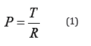
Where; P denotes pressure (Pa), T is the tension in the cylinder wall (force per unit length; newton/meter) and R is the radius of the cylinder (m).
Leung WY et al. [4] designed a new model for compression pressure based on the Laplace’s law. Objective of their research was to design pressure prediction model incorporating different factors as given below
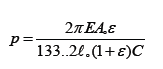
Dubuis L et al. [5] studied patient specific FE model leg under elastic compression and design a model to evaluate compression pressure. They established a theoretical model that is given below

The main objective of current research includes modification of Laplace’s law; development of mathematical model for prediction of compression pressure by incorporating some new parameters including true stress, true strain, true modulus, and deformed width etc.
Experimental
Materials
All of the socks samples were evaluated for their built-in physical and technical specifications as shown in Tables 1 & 2.
Table 1:Physical specifications of compression socks.

*CCL= Compression class level
.Table 2:Technical specifications of compression socks.

*MF=Multi-filament yarn,*ACV=Air covered yarn,*SCV=Single covered yarn, *DCV= Double covered yarn.
Methods
Measurement of compression pressure: Evaluation of compression pressure was done using MST MKIV (Salzmann) as shown in Figure 1.
Derivation of Mathematical Model
Theoretical background
Figure 1 is describing the mechanism of force of exertion from internal side of circular stretched cut strips per unit area of small arc length (dL= R.dθ) and reversal force of exertion assumed to be interface compression pressure (P). Due to static equilibrium condition

Total sum of forces will become

Figure 1:(a) MST Pressure measuring device (b) Mechanism of suppression of circular cut-strip due to wooden leg.

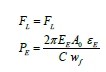
Where P can be replaced by P.sinθ so above equation will become
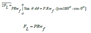
Here FL is stretching force (circumferential force) of cut-strip around the leg, P is pressure [N/mm2], R is radius of wooden leg, wf= deformed width of socks strip around the leg [6].
Relationship between engineering Young’s modulus E.Y.M) and compression pressure (Ps) Engineering modulus
Take an ideally elastic material satisfying Hooke’s law and let Eσ be the engineering stress and Eε be an engineering strain Then, Young’s modulus E is defined as the ratio of stress to strain so we can write.
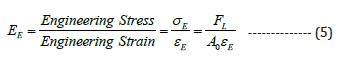
Here lσ is engineering stress; lε is engineering strain while lE is modulus of elasticity [7]. Comparing equation (4) and equation (5), we can get
Relationship between true Young’s modulus of elasticity (T.Y.M) and compression pressure (Ps) True elastic modulus/ Young’s logarithm modulus
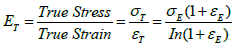
Equation (4) and (7) can be modified to
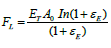
Equating equation (1) and equation (8), relation will become
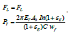
Equation (9) can be named as Model 1 with respect to true Young’s modulus (T.Y.M)
Calculation of pressure measurement , experimental measurement of compression
In order to measure compression pressure we put on the socks samples on wooden leg keeping the MST Salzmann sensors sleeve between wooden leg and sock samples are given in Table 3. Force Vs practical extension results were measured using Testometric tensile tester for calculation of stress and strain values.
Table 3:Measurement of engineering stress, strain, modulus and theoretical compression (PE).

Results and Discussion
Measuring results of engineering stress(Eσ) true stress(tσ), circumferential strain (Eε), engineering modulus (EE) true modulus (tE) along with theoretical engineering pressure (EP), experimental pressure (PS) results are given in Table 3. While deformed width (fW) was measured results by donning the sliced cut strip in Table 3. Figure 2 portray that the coefficent of determination value (R-square values) of Model 2 (E.Y.M) explaining 97.02% of experimental results. Figure 2 portray that the coefficent of determination value (R-square values) of Model 1 (T.Y.M) explaining 97.02% of experimental results.
Figure 2:Linear regression analysis of Model 1(T.Y.M) and Model 2 (E.Y.M) pressure.

Conclusion
In this research we have : Modified the Laplace law by incorporating the new term of deformed width (fW). We developed the two new models; Model 1 (T.Y.M) as well as model 2 (E.Y.M) by incorporating some new parameters including true stress (tσ), true/logarithm strain (tε), true modulus of elasticity (tE), deformed width (fW) along with measurement of engineering stress (Eσ), engineering strain (Eε) and engineering modulus of elasticity (EE) at b position (ankel, minimum girth area) expressions into Hook’s Law and modified equation of Laplace’s law. Statistical validation of newly developed models using linear analysis technique comparison to experimentally measured compression pressure results.
Acknowledgement
Current resaerch is supported by the Department of Clothing Technology, Technical University of Liberec, Czech Republic.
References
- Macintyre L, Margot B, Weedall P (2006) The study of pressure delivery for hypertrophic scar treatment. In: Anand SC, et al. (eds), Medical textiles and biomaterials for healthcare. Cambridge, UK, pp. 224-227.
- (2015) Wall tension and Laplace’s law.
- (2003) Understanding compression therapy, Position Document, Oxford, UK.
- Leung WY, Yuen DW, Ng SP, Shi SQ (2010) Pressure prediction model for compression garment design. J Burn Care Res 31(5): 716-727.
- Dubuis L, Rohan PY, Avril S, Badel P, Debayle J (2011) Patient-specific FE model of the leg under elastic compression. 10th International Symposium on Computer Methods in Biomechanics and Biomedical Engineering, Berlin, Germany.
- Wang L, Felder M, Cai JY (2011) Study of properties of medical compression garment fabrics. Journal of Fiber Bioengineering and Informatics 4(1): 15-22.
- Cieślak M, Karaszewska A, Gromadzińska E, Jasińska I, Kamińska I (2017) Comparison of methods for measurement of the pressure exerted by knitted fabrics. Textile Research Journal (17): 2117-2126.
© 2022 Hafiz Faisal Siddique. This is an open access article distributed under the terms of the Creative Commons Attribution License , which permits unrestricted use, distribution, and build upon your work non-commercially.
Editor In Chief


.jpg)


Signup for Newsletter

Quick Links
 Editorial Board Registrations
 Submit your Article
 Refer a Friend
 Advertise With Us
Our Recent Edition

.jpg)


Top Editors


.jpg)


.bmp)
.jpg)
.png)
.jpg)


.jpg)


.png)

.png)


.png)


Financial Support

Sponsors

Latest e-Books

Latest Video

 a Creative Commons Attribution 4.0 International License. Based on a work at www.crimsonpublishers.com.
Best viewed in
a Creative Commons Attribution 4.0 International License. Based on a work at www.crimsonpublishers.com.
Best viewed in