- Submissions

Full Text
Trends in Textile Engineering & Fashion Technology
Strength Predictions of Multi-Bolted Joints in Woven Fabric Kenaf Composite Plates with Different Configurations Using Xfem Frameworks
Supar Khairi* and Ahmad H
Department of Structures and Materials Engineering, Universiti Tun Hussein Onn Malaysia, Malaysia
*Corresponding author: Supar Khairi, Department of Structures and Materials Engineering, Faculty of Civil and Environmental Engineering, Universiti Tun Hussein Onn Malaysia, 86400 Parit Raja, Batu Pahat, Johor Darul Takzim, Malaysia
Submission: February 14, 2018;Published: May 04, 2018

ISSN 2578-0271Volume2 Issue3
Abstract
Multi-bolted joints are designed as joining technique to provide efficiency in assembling different structure parts; however the ability of neighboring bolts to transfer by-pass stress susceptible to net-tension failure occurrence. More recently, strength prediction works in composite structures are carried out within finite element framework to utilize advantage of advanced computing technology. Current work implemented a three-dimensional Extended Finite Element Method (XFEM) framework of multi-bolted joints configurations in variations lay-ups to determine failure load, validated against experimental datasets. Other testing parameters investigated comprised of different bolts configurations and plate geometries. Visual tracking from XFEM contour found that crack initiation and propagations are consistent with experimental observations. Better agreements were found in nonstaggered configurations with largest discrepancy of approximately 30%, mostly gives less than 15%. Besides, combination of cross-ply and thicker plates promotes better predictions due to larger repetitive plies as current work implemented smeared-out properties within its constitutive model.
Keywords: XFEM; Natural fiber; Multi-bolts; Mechanical testing; Failure mode
Introduction
Due to energy efficiency, material researchers in over the world tend to produce high-performance engineering materials that not only possess excellent mechanical properties but also light to offer superior specific strength and stiffness. One class of advanced materials is regarded as “composite materials” comprised of reinforcing fibers and matrix binders. Conventional composites available commercially is carbon fiber polymer composites (CFRP) which was formerly used in automotive and aircraft industries, but due to price drop over the last 50 years has wingspread to other sectors including civil engineering applications. However, production of carbon fiber requires emission of hazardous gas to the environment and leads to environmental pollution. Natural fibers have becoming great attention among material engineers due to excellent mechanical properties and able to offer cheaper reinforcing fibers with low density. One of the natural fibers formerly used as raw materials in pulp and furniture production is kenaf fibers, Nishino et al. [1] reported that kenaf fibers demonstrates excellent modulus of elasticity and elongation at break.
Structures assembly using bolted joint technique require drilling holes that introduce stress concentration at the vicinity of the notch. Bolted joints are favourable as it able to be dismantled for easy inspections and repairs without prior surface preparations. Romayne [2] carried out experimental work on single open-hole kenaf fabric reinforced polymer (KFRP) composite plates and found that notched strength is largely dependent upon plate thickness, whole sizes and lay-up types. Their work was extended by Supar [3] to multi-holes configurations and found that the failure prone to occur in net-section failure modes with smaller net-sectional arsea, Anet of the composite plate. There are three prominent failure modes takes place in bolted joints, i.e., net-tension, shear-out and bearing failures. However, in bolted joint problems, complex damage morphologies were dependent upon few variables such as clamping load, lay-up types and plate geometries. In multibolted joints, net interaction between bearing stress and by-pass loading to adjacent bolts prone to net-tension failure to occur. Crews [4] initially proposed bearing-bypass interaction envelope for CFRP in unidirectional loading, then later extended by Hung [5] to propose damage accumulation model for strength prediction subjected to bi-axial load. However, both models ignore out-ofplane responses such as bolt bending and unsymmetrical loading effect. Other variables affecting the multi-bolts joint strength are plate geometries, the bolt load conditions and bolt configurations.
Godwin et al. [6] conducted an experimental study of glass fiber reinforced polymer (GFRP) multi-bolt joints series and found that vertical multi-bolt arrangements to loading direction were weaker than horizontally configurations. Experimental investigations on single-row CFRP with three-bolt joints were carried out by Mc Carthy [7] and found that by increasing bolt pitch equally leading to more evenly load sharing among adjacent bolts. Cunningham et al. [8] conducted an experimental study in multi-holes configurations of unidirectional GFRP plates, however they found that larger failure path occurred within staggered hole arrangements to promote better joint strength. On the contrary, crack failure patterns in natural fibers composites are different due to less ductility compared to glass or carbon fiber composites. There is no study had been reported on multi-bolted joints of woven fabric kenaf composite plates (there are very few studies on CFRP and GFRP composites with simplified assumptions) under quasi-static loading.
Emerging computing technology enables to predict the strength of engineering materials by using numerical approaches. Extended Finite Element Method (XFEM) was introduced by Moes et al. [9] and then was implemented in predicting bearing stress at failure in single-bolt single-lap and double-lap CFRP joints [10]. XFEM is extended from classical finite element expression which has enhanced function to enable the crack be tracked visually. A benchmarking work by Cunningham et al. [8] based on experimental framework has been carried out in 2-D finite element analysis using extended finite element method (XFEM) approach [11]. Reasonably good agreements to experimental datasets were found, but the fracture energy value used by the respective authors [12] was taken from woven fabric GFRP plates. This may lead to misleading predictions as Cunningham’s used material based on unidirectional GFRP.
Current works conducted an experimental framework on multi-bolts configurations woven fabric kenaf reinforced polymer (WKRP) composite plates to include joint variables such as bolts configurations, lay-up types, and plate thickness as specified in the testing series. 3-D finite element analysis frameworks were carried out thereafter to predict failure load of composite plates by using independently determined material properties, the numerical modeling results are then validated against experimental datasets. The modelling framework explicitly includes frictional loading transfer, clamping load and surface interactions by using ABAQUS CAE Version 6.13 by implementing physically-based constitutive law.
Experimental frameworks
This section described the testing composite plate preparations, testing series and mechanical testing. The determination of independently elastic and materials properties were also carried out and implemented within finite element modelling at later stage.
Testing plates preparation
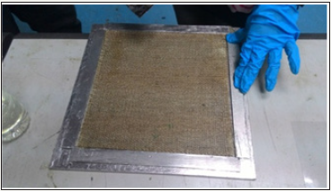
Kenaf fibers used were readily available in twisted yarn with nominal diameter of 0.7mm stored in a box and wrapped with plastic to avoid hairy string formation. Kenaf yarn were weaved using weaving handloom machine and fabrication stage includes stacked weaved kenaf layer and combined with epoxy resin and hardener with mixing ratio was taken as 2:1 to produce WKRP composite panels as shown in Figure 1. Thermosets polymer of epoxy resin provides good contact bond with hydrophobic natural fiber compared to polyester resins and vinyl ester resins. WKRP composite panels of 240×240mm were fabricated at Fabrications Laboratory, Universiti Tun Hussein Onn Malaysia (UTHM). WKRP lay-up types used were plain weave cross-ply and quasi-isotropic their stacking sequences and nominal plate thickness were specified in the testing series. The composite panels were allowed to harden for 24 hours under high pressure and visible voids were inspected accordingly.
Figure 1: WKRP combined with epoxy resin to produced composite plates.
WKRP plates were sectioned using high speed saw cutter to allow easy cutting and good edge finishing and carefully conducted to prevent any surface edges defect. Circular holes with 5mm diameter, d was drilled according to specified bolt location with nominal pitch spacing, p=4d between adjacent holes and care should be taken to ensure no hole edge break-out. Plate thickness and width of each testing plates were measured by using micrometre and vernier calliper respectively. The fastener systems used in current joint configuration system are steel washers and steel bolts. M5 bolts and washers were installed and 5Nm clamping torque was applied using torque wrench immediately prior to mechanical testing to avoid bolt relaxations. Two steel washers were provided below the bolt head and above the nut to provide lateral pressures in out-of-plane direction as shown in Figure 2.
Figure 2: Schematic of steel washers in single-lap joint configuration.

Testing series and mechanical testing
The testing series implemented in current work consists of seven multi-bolts configurations given in Table 1 comprised of four non-staggered and three staggered configurations. The end distance, e1 and edge distance, e2 were respectively set constant to 3d and the normalised pitch distance, p/d is 4 [13]. Spacing between nearest adjacent holes was given as symbol p and g respectively as given in Figure 3. Mechanical testing of testing plates was carried out under quasi-static tensile loading using an Instron Universal Testing Machine (UTM) with 100kN load cell and crosshead speed of 0.2mm/min, following ASTM standard D3039. Load and displacement profiles were recorded at one-second intervals using a PC data-logging package from Instron. The testing plates were labelled accordingly as specified in the testing series. Each testing series investigated were prepared with at least three sets of testing plates and standard deviation of less than 5% to demonstrate good reproducibility of testing results were obtained. A total of 21 WKRP testing plates were tested throughout the testing series.
Figure 3: Schematic of hole location in multi-bolted joints.
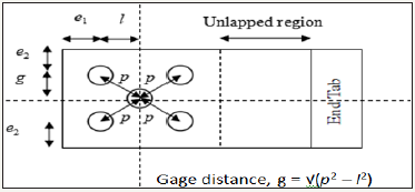
Table 1: Testing series implemented in current work.

Figure 4: Testing plate’s geometry of all testing series tested.

A representation of multi-bolts single-lap joint configurations assemblies in current work is illustrated in Figure 4. Aluminium plates were used as joining plate to all configurations series follow joining WKRP parts. Higher relative modulus in aluminium plate allows plate failure to take place within WKRP plates. As the aluminium plates were reused in following testing work, it was customary to make sure that the aluminium plates do not warp during testing. Current work used aluminium plates (thickness=4mm) with yield strength of 100MPa to avoid permanent deformation in aluminium plate to allow repetitive use. A spacer was placed at end tab during mechanical testing to avoid primary bending to occur during mechanical testing.
In single-lap bolted joints, primary bending was avoided by providing spacer of similar thickness in adjacent plates during mechanical testing. However, secondary bending was unavoidable due to unsymmetrical loading path and it was seen during mechanical testing, consistence with other findings [14]. In singlelap joint configurations, secondary bending phenomenon occurred that may give additional tensile stresses that may decrease the joint strength [14]. Nevertheless, the secondary bending effects does not lead to any significant change in load displacement profile but slightly reduce joint strength compared to double-lap joints configurations.
Determination of independently elastic and materials properties
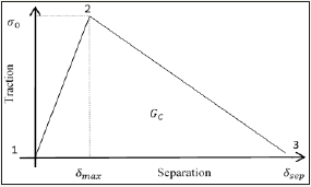
Table 2 shows the elastic and material properties of all lay-up investigated in current work. The elastic properties include inplane tensile modulus, (Exm/Ey), shear modulus, Gxy and Poisson’s ratio, vxy. These properties were determined experimentally and these values were taken as “smeared-out” properties. On the other hand, out-of-plane properties were determined from expression available from literatures [15]. The constitutive model used based on traction-separation relationship, requires material properties parameters i.e., un-notched strength, σo and the fracture energy, Gc as shown in Figure 5. These material properties were determined independently in the laboratory following relevant code of practice. The isotropic steel bolts and steel washers were assigned with elastic modulus, Es=210GPa and Poisson ratio, v=0.3.
Table 2: Elastic properties of WKRP lay-up used in current work.

Figure 5 shows a physically-based constitutive model was implemented based on traction-separation relationship. The maximum cohesive stress is given at the maximum separation length and equivalent to un-notched plate strength, σo and area under the curve is given as fracture energy values, Gc. Three points were highlighted in Figure 5, no material separation has occurred between Points 1 and 2. As the separation increased, cohesive traction achieves a maximum cohesive stress as labelled in Point 2. Between Points 2 and 3, cohesive traction decreases and finally stopped at Point 3 enable complete material separation and provide energy absorption for de-cohesion.
Figure 5: Physically-based constitutive model used in current work.
Finite element modelling (FEM)
Current model implemented 3-D modelling framework, therefore the frictional load transfer and bolt load were physically represented. In 3-D modelling framework, effect from secondary bending, bolt tilting, joining plates sliding, bearing contact and applied bolt load were explicitly modelled. It is expected that effect of secondary bending is less significant in multi-bolts problem compared to single-bolt problem due to less bolt tilting in multibolts problem leading to less edge lifting. In some cases, secondary bending effect may give bolt tilting and washers digging onto the composite surface as reported in single-bolt CFRP single-lap joint. Exhibition of secondary bending increases the tensile stress, and therefore reduce the loading capacity of respective composite plates compared to equivalent double-lap joints.
Current work on three-dimensional multi-bolted configurations models were developed in ABAQUS CAE 6.13 following experimental testing configurations as described previously. Finite Element Modelling can be divided into three stages which are preprocessing stage, processing stage and post-processing stage. Preprocessing stage is the essential stage comprised of few steps such as modeling techniques, element discretization, and loading and boundary conditions. The description of implementation bolt load was also described in subsequent sub-section.
Pre-processing works
Three-dimensional modelling frameworks were modelled as half-model (except configuration E due to no existence of symmetrical axis) following experimental configurations of singlelap multi-bolted joints to reduce computational time and effort. The models were explicitly modelled out-of-plane effect including frictional load transfer, bolt clamp-up and surface interaction. Many previous researchers combine washer and bolts as a single unit for simplicity [10,16], but bolt parts as separates modeled to allow explicitly frictional load transfer within joining plates. The bolt head, bolt shaft and nut were modelled as a single unit where the clamping loads (bolt load) were implemented within internal surface of bolt shaft as suggested by ABAQUS CAE documentation [17]. Perfect fit case was assumed in all models to eliminate the effect of clearance, these effects are more critical in aerospace sector as stringent low tolerances of clearance were set. The washer is modeled under bolt head and above nut in each bolt shaft, resulting to three bolts and six washers were used.
The boundary conditions and applied loading were assigned, where fixed boundary was assigned at left edge and applied loading was assigned at the far-right edge shown in Figure 6. Y-symmetry was assigned at the y-axis to represent half-model configurations as idealized previously. All surface interactions were modelled as “master-slave” interactions and penalty friction value were implemented with friction coefficient of 0.3 and 0.1 for compositecomposite and composite-steel surfaces respectively [10]. Master surface was assigned in materials with larger modulus and exhibited less deformable than relatively weaker joining materials (assigned as slave surface). The contact between two surfaces was modelled as small sliding and surface-to-surface as sliding formulation and discretization method respectively. Combination of small sliding and surface-to-surface discretization gives more realistic physical perturbation and cover larger contact area between contact pairs. XFEM regions were assigned within the net-tension plane at the vicinity of Bolt 1 as observed failure occurred during mechanical testing.
Figure 6: Boundary condition and loading applied of 3-D multi-bolted joints model.

All surface contact interactions region involved within each bolt and all surface interactions were modelled as master and slave interactions. However, each model in multi-bolted joints implemented here has between 17 to 41 contact interactions dependent upon number of bolts as opposed to only nine contact interactions applied in single-bolted joint [10]. Meshing of slave region was assigned finer than master region counterparts, as required by ABAQUS CAE documentations. Small sliding was chosen as sliding interactions to allow significant movement of nodes. This is important as assigning contact surface will transfer the load affect the stress distribution and strength prediction of model.
The mesh ahead at vicinity of whole edge plates were refined and remaining plate regions were made coarser to save computational effort as shown in Figure 7. Full integration method was implemented to avoid hour-glassing effect (in the case of using reduced integration technique). Meshing refinements were independent upon strength predictions as constitutive model used is driven by energetic approach. The damage stabilization value of 1x10⁻⁵ was implemented throughout all models. These sensitivity values were referred to Ahmad [10] work on CFRP plates and Supar [3] on multi-holes WKRP composite plates. Firstorder brick element with element designation code of C3D8I (an 8-node linear brick, incompatible modes) was used as element type. These elements were chosen as only first-order elements and brick elements were compatible in current standard ABAQUS Version 6.13 with XFEM framework. Shear locking phenomenon are prone to occur in brick elements type, however these effects can be substantially removed by using incompatible modes.
Figure 7: Meshing of 3-D multi-bolted joints model in configuration B (the notch edge is enlarged for visual clarity).

Implementation of bolt load
Figure 8: Joint behaviour of testing plate in configuration B.
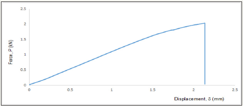
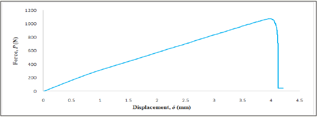
A representative of load-displacement profile curve is shown in Figure 8. Joint behaviour during mechanical testing can be divided into three major stages which are identified as non-slip region, slip region, bearing contact and failure load. Initially, the joint deformation is contributed by linear elastic within unlapped plate region. At this stage, no slippage occurred as applied load, Papp<clamping load, Pbolt and the applied load is transferred genuinely through friction. Thereafter, slippage occurred at shear plane when Pbolt exceeds Papp, then the load transfer is borne by individual plates. The amount of friction exhibited dependent upon the surface roughness between joining plated and also between washers and joining plates. Then, the clearance is taken up and bearing between bore hole and bolt shaft occurred until up to fairly high stress. Finally, peak load was demonstrated and recorded prior to catastrophic failure. However, as micro damage event occurred beneath washers (one located below bolt head and another place at upper nut), crack initiation and crack growth from notch tip were not visually seen during mechanical testing. From experimental results, the sliding load in Figure 8 is given by plateau curve under slip region and occurred at 1804N. Bearing contact between bolt shaft and bore whole occurred thereafter and exhibited bearing stress within bearing area, a product of whole size, d and plate thickness, t.
Figure 9: Calculation of bolt load
(a) Configuration B
(b) Configuration C
(c) Configuration F implemented in FEA modelling.
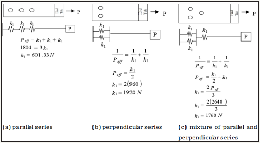
Figure 10: Bolt load applied in current work.
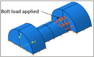
The procedure to assign bolt loads were followed as suggested by ABAQUS CAE 6.13 documentation [17], where the bolt is assigned with pre-tensioned load prior to far-field stress applied. The bolt load calculated was referred accordance to spring analogy [18], where the whole elongations were assumed as spring deformation and schematically given in Figure 9. In spring analogy, two springs arranged in parallel series has stiffness constant of k1 as labeled in Figure 9. A constant force, P is exerted to provide similar extensions in all springs placed in parallel series. On the contrary, springs arranged in perpendicular series, provide larger springs extension and less whole elongation is expected in perpendicular series than parallel series. Correspondingly, an applied force, P is equivalent to effective force which is reciprocal of each bolt. Sample of calculation of spring stiffness with respective to various configurations tested were given in Figure 9. The bolt load was required by applying pretension force within internal region of bolt shaft during pre-loading step (Step 1), resembling to the clamping force applied to the nut shown in Figure 10. Subsequently during the loading step (Step 2) the bolt load was kept constant (fix at current length) to idealize application of bolt torque immediately prior to mechanical testing.
Result and Discussion
Experimental results and validation work of strength prediction of FEA modelling with experimental datasets were given in this section.
Experimental observations and results
Figure 11 showed photographs of all multi-bolts configurations investigated failed in net-tension mode, consistence with Godwin [6]; McCarthy’s et al. [16] works where effect of material yielding is negligible. All testing series plates were showing similar trends, net-tension failure was exhibited in outer bolt nearest with applied loading and slightly bearing failures exhibited to other holes. It is expected that higher bearing stress at outer bolt is exhibited compared to other bolts as it was the first hole that made contact with bolt shaft corresponds to highest bearing stress borne as remote load applied. Similarly, larger number of bolts contributed to lower bearing stress borne by outer bolts due to larger friction from adjacent bolts.
Figure 11: Failure pattern in all multi-bolts configurations.
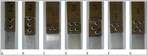
As applied tensile force increased, crack growth was more visible across the net-tension plane perpendicularly to applied loading directions until critical damage length associated to catastrophic failure as critical length has exceeded. The failures were caused by stress concentration at the notch tip leading to crack initiation and crack propagations perpendicularly to remote loading directions. It was found that the crack is initiated slightly away from net-sectional plane due to taken up clearance and hole elongation prior to bearing contact between bolt shaft and hole plate at hole angle of approximately 87°. The fracture and failure at the vicinity of hole edge comprised of extensive micro-damage events in the form of matrix cracking, delamination and ultimately by fiber fracture. A damage zone was formed ahead of the notch tip and crack exceeding damage zone length gives the peak load and associated to catastrophic failures thereafter.
The results showed that PX4 series exhibits higher failure load due to higher volume fractions of 0° fibers in cross ply compared to quasi-isotropic lay-ups counterparts. Nevertheless, quasi-isotropic lay-up has better resistance against shear due to existence of 45° plies as maximum principal shear plane occurred in 45° angle. It was found that increase of up to 12% failure load in cross-ply lay-ups were exhibited. As a result of secondary bending due to unsymmetrical loading path, the plate edges were found lifted and contribute to extra tensile stresses and associated with reduced loading capacity to respective composite plates. However, it was expected that larger amount of edge lifting found in WKRP then aluminium plates, contrary to similar amount of plate edges lifting if both joining plates are made of similar material. It was found that the presence of secondary bending phenomenon is more significant among thinner lay-up series, where PX4 series can withstand up to 50% failure load than PX2 series. Although thicker lay-up has larger failure load, but produced lower bearing stress as larger bearing area associated to lower resistance in out-of-plane direction, prone to delamination to occur.
Generally, more number of bolts associated to larger frictional load transfer prior to slippage and provide higher effective bolt load, Pbolt and the applied load is transferred genuinely through friction and gives higher strength at failure. Therefore, largest number of bolts in configuration G and D gives the optimum failure load compared to other configurations in staggered and nonstaggered series respectively. With respective to lesser plate width, configuration A and B shows relatively lower failure load compared to other configurations. However, larger (approximately 10%) failure load was demonstrated in configuration B due to larger number of bolt. Bear in mind the hole configuration A and B has only one row with variation in bolt number, therefore net-sectional area in these series are similar. On the contrary, in thinner lay-ups (i.e., PX2), configuration A and B gives contrary findings due to former configuration gives slightly more secondary bending effect compared to latter configuration as more bolts able to refrain larger edge lifting. He also found that increasing failure load in multi bolted joints is not directly proportionate to more bolts number but also dependent upon plate geometries, lay-up types and hole configurations [19]. In staggered series, configuration F gives lower failure load than configuration G due to less bolt number and associated friction load to surpass far-field stress, however substantially smaller failure load difference in both cases (less than 6%) is due to smaller unloaded region as two outer bolts were arranged vertically. Moreover, the effect of number of bolts ahead of outer bolts not much contributes to failure load as failure path was passing across outer bolt along net-tension plane, less difference in failure load exhibited between both configurations to all lay-up series are much expected.
It was found that staggered bolted joint has higher joint strength than non-staggered counterparts. Due to requirements of gage distance, g bolt positions and whole arrangements, wider testing plate’s width were provided in staggered series. Staggered joint is designed to obtain more effective usable area within neighboring bolts, which may promote lengther net-tension failure path associated to “zig-zag” path [20]. However, in current work of staggered bolts series does not exhibited “zig-zag” path but showing net-tension failure plane across their outer bolt, this may due to higher modulus in GFRP than WKRP plates. Variation of staggered hole configurations gives different distribution of by-pass stress transferred to their neighboring bolts [21] and correspondingly affected their joint strength. Multi bolted joints are commonly used in most engineering sectors due to design constraint, however the ability of bolt to transfer by-pass stress to their adjacent bolts that prone of net-tension to occur in multi-bolted configurations. However, in staggered arrangement were gives higher inner stress within their congested region and reduces it resistance against applied load.
Comparison of experimental results with FEA modelling
A representative load-displacement curve of PX2 lay-up with configuration B (non-staggered configuration) and configuration G (staggered configuration) were given in Figure 12. All testing series demonstrated a clear plateau at early stage of load-displacement curve to idealize assigned pre-bolt at first loading step. Figure 13 shows the visually of failure path at outer bolts (given as bolt 1 in the respective Figure 13) associated to highest bearing stress exhibited. From FEA modelling curve, the damage plots at the selected points in the load-displacement curve are shown in Figure 14. Initially, as observed experimentally the linear elastic at the early stage was contributed by un-lapped plate region. At the point A, it showed the crack initiation took place but the respective plate still able to carry more load until ultimate load as labelled at point B. Ultimate load is given as the crack exceeds approximately the hole size radius. Soon after reaching point B, the catastrophic crack occurred to complete separation.
Figure 12: Load-displacement curve (a) configuration G (b) configuration B from experimental results.

Figure 13: Failure in FEA modelling (configuration B).

Figure 14: Load-displacement curve in XFEM modelling (configuration B).
Micro damage events ahead of the notch tip comprised of matrix cracking, delamination and fiber fracture. The peak load obtained is ultimately dependent upon fiber tow fracture. It is expected that similar number of tow fractures occurred on the left and right side of hole edge are expected (to enable the model to be idealized as half-model). It is also expected that similar number of tow fracture occurred in all respective layers of each lay-up to resemble selfsimilar crack behaviour across plate thickness. This argument is only can be validated by conducting interrupted test at 90% failure load level, however it is outside the scope of the current paper. This argument is based on stress concentration problem of open hole plates as reported in GFRP [22] and CFRP [23] and single-bolt GFRP case [24] to disseminate self-similar crack behaviour.
Table 3 showed comparison between experimental datasets and FEA modelling results in all testing series investigated. From Table 3, good agreements were found in non-staggered configurations with discrepancy less than 30%, mostly gives less than 15%. Less good agreements in staggered configurations may due to more parameters involved to comprise of larger contact interactions, larger bearing area and complex stress distributions exhibited, therefore larger discrepancies are perhaps not surprising. In nonstaggered configurations with same bolts number, configuration C provides better agreement than configuration A, where configuration C exhibited lesser hole elongation, configuration A demonstrates more elliptical hole shape as a results of larger hole elongations. It is expected that better predictions are shown on configuration C due to less hole elongation exhibited (current work used “smeared out” properties that may not physically represented hole elongation than larger hole elongation in hole parallel series.
Table 3: Comparison of strength at failure between experimental results and XFEM predictions in current work.

Respective to plate thickness, thicker plates of PX4 gives better agreement of less than 16% discrepancy than PX2 layups counterparts. Similar finding was found in [11] where better strength prediction in thicker unidirectional GFRP multi-holes plates, benchmarking work from experimental work conducted by Cunningham et al. [8]. Secondary bending phenomenon can be captured properly in 3-D modelling, however, current approach implemented smeared-out properties which is more representative in thicker plates as average plate properties were taken place. Furthermore, the secondary bending phenomenon is smaller in thicker plate as smaller edge lifting exhibited provides better strength prediction in thicker plates. In comparison to layup types, cross-ply series gave best prediction than quasi-isotropic lay-ups (mean discrepancy in PX4 is 7% compared to 11% in PQ4 series), repetitive layer sequence in cross-ply lay-ups gives better representation of smeared-out properties. Combination of thicker and cross-ply lay-ups gives good agreement, less than 16% discrepancy was given than other lay-up series.
Concluding Remarks
Current works were implemented 3-D modeling framework then validated against experimental results, therefore the load transfer due to friction and bolt load was physically represented. In 3-D modeling framework, effect from secondary bending, joining plates sliding, bolt tilting, applied bolt load and bearing contact were explicitly modeled. As expected, multi-bolted joints are prone to nettension failure and in-line with analytical approach due to ability of by-pass loading transfer to its adjacent bolts. Good agreements were found in all testing series with less than ±30% discrepancy. Better agreements were found in non-staggered configurations due to less contact interactions and complex stress distributions. All testing plates displayed net tension failure, which is associated with the stress concentration at the vicinity of the holes. These failures occurred as crack initiation and crack propagated from the notch tip across net-tension plane and associated to catastrophic failures thereafter. Better agreements were showed in thicker plates of PX4 of less than 16% discrepancy than PX2 lay-ups counterparts. Finite element modeling implemented smeared-out properties which is more representative in thicker plates due to less secondary bending effect than thinner plates Besides, cross-ply (PX4) lay-ups gave best prediction than quasi-isotropic (PQ4) lay-ups, where repetitive layer sequence in cross-ply lay-ups more representation of smeared-out properties. This leading to best agreement in combination of thicker plates and cross-ply lay-ups as shown in PX4 series of less than 16% discrepancy.
References
- Nishino T, Hirao K, Kotera M (2006) X-ray diffraction studies on stress transfer of kenaf reinforced poly (L-Lactic Acid) composite. Composites Part A: Applied Science and Manufacturing 37(12): 2269-2273.
- Romayne AH, Ahmad H (2016) Notched strength of woven fabric kenaf composite plates with different stacking sequences and hole sizes. Matec Web of Conferences 10: 1-6.
- Supar K, Ahmad H (2017) Multi-holes configurations of woven fabric kenaf composite plates: experimental works and 2-D modelling. International UNIMAS Stem Engineering Conference pp. 1-9.
- Crews JH, Naik RA (1986) Combined bearing and bypass loading on a graphite/epoxy laminate. Composite Structures 6(1-3): 21-40.
- Hung CL, Chang FK (1996) Strength envelope of bolted composite joints under bypass loads. Journal of Composite Material 30(13): 1-34.
- Godwin EW, Matthews FL, Kitty PF (1982) Strength of Multi-bolt Joints in GRP. Composites, Joining in fiber-reinforced plastics 13(3): 268-272.
- McCarthy CT, Gray PJ (2011) An analytical model for the prediction of load distribution in highly torqued multi-bolt composite joints. Composite Structure 93(2): 287–298.
- Cunningham D, Harries KA, Bell AJ (2015) Open-hole tension capacity of pultruded GFRP having staggered hole arrangement. Engineering Structures 95: 8-15.
- Moës N, Sukumar N, Moran B, Belytschko T (2000) An extended finite element method (XFEM) for two and three-dimensional crack modelling. ECCOMAS.
- Ahmad H (2014) Strength prediction in CFRP woven laminate bolted single-lap joints under quasi-static loading using XFEM (2014). Composites Part A: Applied Science and Manufacturing 66: 82-93.
- Supar K, Ahmad H (2017) XFEM modelling of multi-holes plate with single-row and staggered holes configurations. MATEC Web of Conferences 103: 1-8.
- Ahmad H, Crocombe AD, Smith PA (2013) Strength prediction of notched composite plates using a cohesive zone approach (2013) Advanced Material Research 845: 199-203.
- American Institute of Timber Construction (2005) Timber Construction Manual. (4th edn), John Wiley & Sons, Hoboken, New Jersey, USA, pp. 239- 269.
- Smith PA, Pascoe KJ, Polak C, Stroud DO (1986) The behaviour of singlelap bolted joints in CFRP laminates (1986) Composite Structures 6(1-3): 41-55.
- Ahmad H (2012) Finite element-based strength prediction for notched and mechanically fastened woven fabric composites. University of Surrey, Guildford, UK.
- Mc Carthy MA, Mc Carthy CT, Lawlor VP, Stanley WF (2005) Threedimensional finite element analysis of single-bolt, single-lap composite bolted joints: Part I - model development and validation. Composite Structures 71 (2): 140-158.
- Abaqus®v (2013) User’s manual and theory manual. Dassault Systèmes Simulia Corp., Providence, RI, USA.
- Socratic (2016) What is the spring constant in parallel connection and series connection?”
- Feo L, Marra G, Mosallam AS (2012) Stress analysis of multi-bolted joints for FRP pultruded composite structures. Composite Structures 94(12): 3769-3780.
- Varma A Chapter 4: Tension member designce. CE 405: Design of Steel Structures. Pp. 1-27.
- Supar V, Ahmad H (2017) Stress distribution study on multi-holes configuration in woven fabric kenaf composite plates. IOP Conference Series: Materials Science and Engineering 127: 1-8.
- Manger CIC (1999) Failure of notched woven GFRP composites: Damage analysis and strength modelling. Guildford, University of Surrey, England, UK.
- Belmonte HMS, Ogin SL, Smith PA, Lewin R (2004) A Physically-based model for the notched strength of woven quasi-isotropic CFRP laminates. Composite Part A 35(7-8): 763-778.
- Kontolatis A (2000) Failure of Composite bolted joints made from woven fabric GFRP composite. MSc dissertation, Guildford: University of Surrey, England, UK.
© 2018 Supar Khairi. This is an open access article distributed under the terms of the Creative Commons Attribution License , which permits unrestricted use, distribution, and build upon your work non-commercially.
 a Creative Commons Attribution 4.0 International License. Based on a work at www.crimsonpublishers.com.
Best viewed in


.jpg)


 Editorial Board Registrations
 Submit your Article
 Refer a Friend
 Advertise With Us
.jpg)


.jpg)


.bmp)
.jpg)
.png)
.jpg)


.jpg)


.png)

.png)


.png)


