- Submissions

Full Text
Techniques in Neurosurgery & Neurology
Establishment of a Rat Model of Neural Injury After High Frequency Monopolar Stimulation of the Motor Cortex
Tao Yu1, Lanjun Guo2*, Jennifer Sasaki Russell2 and Jeffrey W Sall2
1Department of Neurosurgery, USA
2Neurophysiological Monitoring Service, Department of Anesthesia and Perioperative Care, USA
*Corresponding author: Lanjun Guo, Department of Anesthesia and Perioperative Care, USA
Submission: August 23, 2021;Published: September 21, 2021
ISSN 2637-7748
Volume4 Issue3
Abstract
Direct electrical motor cortex stimulation with short-train High-Frequency Stimulation (HFS) for Motor Evoked Potentials (MEPs) has been used during supratentorial surgeries, but the safety threshold is poorly defined. This study aimed to establish a rat model for the investigation of neural damage in the cerebral cortex caused by high current HFS to aid in defining safety thresholds. We performed bilateral craniotomy on 12 rats. Cerebral sensory-motor cortex in one hemisphere was stimulated with a highfrequency current for 100 times. The rats were sacrificed, and the brains were sliced for Nissl, DAPI, and IBA-1 staining. Neural damage of the cerebral cortex was found in all cases, including markedly shrunken and pyknotic cells. IBA-1 staining revealed reactive microglia morphology in the lesion. DAPI staining showed nucleus degeneration and deformation. The cell density was significantly lower within the lesion compared to the contralateral unstimulated hemisphere. This study has established a brain lesion model caused by HFS on rats. These results suggest HFS may carry a risk of serious neural damage if repeatedly applied to the same brain site. More experiments are needed to fully understand the safety threshold of direct cortical stimulation with HFS for clinical use.
Keywords: Brain injuries; Direct cortical stimulation; High-frequency stimulation; Motor evoked potentials
Abbreviations: D: Duration of Each Pulse; HFS: High-frequency Stimulation; I: Current Intensity; IONM: Intraoperative Neurophysiological Monitoring; LFS: Low-frequency Stimulation; MEP: Motor Evoked Potentials; PFA: Paraformaldehyde; PBS: Phosphate-buffered Saline; Q: Charge Per Pulse; Qt: Total Charge; QDt: Total Charge Density
Introduction
Intraoperative Neurophysiological Monitoring (IONM) is used to reduce the risk of neurological deterioration during neurosurgical procedures [1-4]. In recent years, shorttrain High-Frequency Stimulation (HFS) has been widely used for functional mapping of the motor area in the cerebral cortex and functional monitoring to detect motor dysfunction during intracranial surgery [5-12]. Direct application of electrical stimulation on the motor cortex may carry a risk of damage to the brain. Most previous studies that investigated safety parameters were based on continuously delivered current or prolonged, continuous 50- Hz biphasic rectangular pulse [13-17]. The safety thresholds for direct cortical stimulation with short-train HFS under varying parameters is largely unknown. At present, the current intensity is generally considered to be safe when under 30mA [9,18]. However, pediatric patients often require higher current to trigger MEPs [19,20]. Under these circumstances, it is necessary to define the safe parameters of HFS to ensure that monitoring itself does not injure the patients. The current safety thresholds used in the clinic for direct cortical stimulation with HFS for motor mapping and monitoring is based on continuously delivered current with Low-Frequency Stimulation (LFS) since there are few studies based on HFS in human or animal models [13-17,21,22]. A previous study reported that 50-mA current HFS caused mild and transient neural damage in the brain on transmission electron microscope slides [16]. No significant neural damage was observed under the light microscope. Thus, a higher current HFS is required in order to induce significant neural injury to establish that a safety threshold exists. In this study, we used a protocol that goes beyond the typical needs of general clinical use. The primary goals of this study are to define characteristics of HFS-injury in the cerebral cortex and establish a protocol for HFS in an animal model. Our results presented here will facilitate future experiments that are needed to determine the precise safety threshold for HFS.
Material and Method
Animals
All studies were approved by the institutional animal care and use committee at University of California, San Francisco, and whenever possible the ARRIVE guidelines were followed. All methods were performed in accordance with relevant guidelines and regulations. P23-P30 Sprague-Dawley male rats weighing 70- 125g were purchased from the Charles River Laboratories (Gilroy, CA, USA) and housed on a 12 h reverse light/dark cycle with ad libitum access to food and water.
Anesthesia and surgery protocol
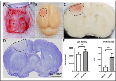
Rats were anaesthetized in an induction chamber with 3.0% isoflurane, and then maintained with 1.0% of isoflurane in air and oxygen (FiO2 50%) for the surgery. Their heads were firmly fixed with ear bars in a stereotaxic frame (David Kopf Instruments, USA). A “U” shape incision was made to expose the skull. Two craniotomies were performed, one on each hemisphere (3mm above bregma and 5mm below bregma with width of 5mm) using a drill. The dura mater was exposed for electrical stimulation (Figure 1).
Figure 1: High-frequency current stimulation site, gross finding, and pathological finding of the motor-sensory
cortex of a rat.
Bilateral side craniotomy was performed for a rat
A. and the dura mater was exposed (*). After stimulation and perfusion, the brain was dissected. The lesion
beneath the stimulation site on the brain surface was pink
B. (dotted lines). The coronal section showed the lesion was a pink color cone-shaped lesion (dotted lines)
which had a relatively defined border
C. Light microscopy of the section also showed an edematous area in a conical manner (dotted lines)
D. (Nissl stain, 4X). The cell density and average cell size were significantly lower in the lesion than the control
side
E. Solid bar represents mean value. Error bars represent standard deviation. *** p 0.001, *** p < 0.0001.
Electrophysiological stimulation protocol
A Cascade IOMAX (Cadwell Industries, Inc, USA) was used for stimulating and recording. The platinum electrode with 3mm diameter of a subdural strip electrode was fixed on the dura mater and used for stimulating. Digitized EEG was recorded during electrical stimulation and 15 minutes after from electrodes placed on the stimulated and contralateral sides. All 12 rats were randomly stimulated on one side of the sensory-motor cerebral cortex. The contralateral side was used as the control side. EMG responses were recorded from identical needle electrodes placed on the triceps brachii and triceps surae muscle. After the stimulation protocol was completed, the skin was closed with suture. All rats were awakened and survived for 5 hours, then were sacrificed for further analysis.
Parameters of electrical stimulation
The stimulus intensity was 100mA. Complete parameters are listed in Table 1. Charge per pulse(Q) is defined as I (current intensity) D (duration of each pulse) for the rectangular pulses. Charge Density (QD) (in microcoulombs/cm2, or μC/cm2) is charge divided by electrode area. Total charge (Qt) and total charge density (QDt) are defined as Q or QD times the number of pulses [23]. Current density (in A/cm2) is applied current at the electrode divided by electrode area.
Table 1: Electrical stimulation parameters in this study.
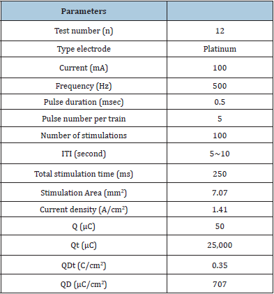
ITI: Intertrial interval; Q: Charge per pulse; QD: Charge density; Qt: Total charge; QDt: Total charge density.
Brain tissue processing and immunohistochemistry
The rats were anesthetized again with isoflurane and perfused with 0.01mol/L phosphate-buffered saline (PBS) (30mL) and 4% Paraformaldehyde (PFA) solution (150mL). After decapitation, the skulls were opened, and brains were carefully dissected. The brains were stored in PFA overnight, then transferred into 30% sucrose. Then they were rapidly frozen and stored in isopentane at -20 ℃. 40μm thick coronal sections were cut on a Leica CM 1850 Cryostat (Leica Microsystems, GmbH, Nussloch, Germany) and mounted onto glass slides. The slides were stained by the Nissl method with cresyl violet and used for quantitative analyses. Free floating sections in the PBS were incubated for 1 hour with 1:2,500 Rabbit anti-IBA-1 (Abcam Inc, Toronto, ON, Canada), 1 hour with 1:500 Alexa Fluor 594 Goat anti-Rabbit secondary antibody (Molecular probes, Eugene, OR, USA), 5min with 1:5,000 DAPI (Vector Laboratories) at room temperature. Sections were mounted onto glass slides and sealed with Fluoro-Gel mounting media and cover slipped. The slices were scanned by Cytation 5 Imaging Reader (4X and 20X) (BioTek Instruments, Inc., USA). Image processing, measurements and cell counts were performed using the FIJI software [24]. The area and volume of each lesion were calculated by its diameter and deepness. Cell counts were obtained by setting the intensity threshold then running the particle count analysis. The cell density was calculated by cell counts divided by area, and the lesion side was contrasted with the control side. The proportion of cell area was calculated by total cell area divided by total area. The thickness of cell layers of cerebral cortex was measured using FIJI software. We evaluated the Layer I and V on 20X the nissl-stained wholebrain coronal sections [25].
Statistical Analysis
Statistical processing and analysis of results were conducted using SPSS (IBM corp., Chicago, USA). The significance of differences was assessed using the two tailed t test for independent variables. P values less than 0.05 were considered statistically significant. All data were expressed as the mean ± standard deviation.
Result and Discussion
Stimulation results
Each of the 12 rats received 100 times of short trains of HFS in one hemisphere. All rats survived the duration of the experiment and respiration rates remained normal throughout stimulation. The motor evoked potential and muscle twitch were triggered during each stimulation. A summary of stimulation parameters is presented in Table 1.
Gross findings
After stimulation, the surface of focal dura mater just below and around the stimulated electrodes showed pink-brown color and swelling (Figure 1). The average diameter of the lesion on the brain’s surface was 4.69 ± 0.56 mm, which was larger than the width of the electrode (3mm). The surface of the brain was smooth and did not adhere to the dura. During the slicing, the cross section of the brain showed a light-brown colored cone-shaped lesion which had a relatively defined border (Figure 1).
Histological changes of the stimulation sites
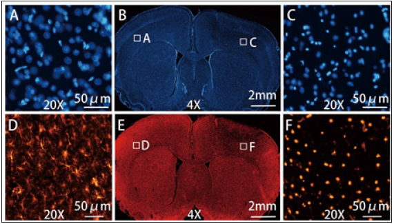
The Nissl-stained slices were examined under light-microscopy and revealed an edematous area extending through the cortex towards the subcortical corpus callosum and the lateral ventricle in a cone-shaped manner (Figure 1). There were 8 rats which presented with discrete hemorrhages within the brain parenchyma under the stimulation site (Figure 1). In the lesion area, there was increased extracellular space and shrunken cells in contrast to the normal tissue (Figure 2). All lesions showed severe damage and the neurons were markedly shrunken and dark in all grey layers and white matter. The columnar organization of neurons were disrupted in all layers. DAPI staining showed some nuclei were deformed (Figure 3). IBA-1 staining of microglia on the control side showed a ramified morphology. In contrast, most microglial under the stimulation site exhibited a dense, spherical morphology (Figure 3).
Figure 3: The morphological changes of cells observed through DAPI and IBA-1 staining of stimulation side and contralateral side. The DAPI staining (B) showed normal cell nucleus of the control side (A) (20X) and the loosened and deformed nucleus in the lesion (C) (20X). The IBA-1 staining (E) showed ramified (or resting) microglia on the control side (D) (20X) and reactive (or phagocytic) microglia in the lesion (F) (20X).
The average area of the lesion on the coronal section and the average volume of lesion with the largest lesion presentation are presented in Table 2. The average thickness of layer I, layer V, corpus callosum, and the entire cortex of the 12 rats were significantly larger on the stimulation side than the control side (p<0.001, <0.001, <0.0001, <0.0001, respectively) (Figure 2). The cell density of the lesion (2217.25±248.59 cell/μm2) was significantly lower than the control side (2544.21±280.25 cell/μm2) (p< 0.001) (Figure 1). The lateral ventricles and corpus callosum were compressed on the lesion side in all 12 cases. The average total cell area within the lesion was 36.77±9.56μm2, which is significantly smaller than that of control side (117.93±32.97μm2) (p<0.0001) (Figure 1). In layer V, most of the motor cells appeared severely shrunken. The ratio of total cell area to total area was 6.42±2.05 % in lesion and 27.41±7.31 % in the corresponding part of the control side
Figure 2: Light microscopy findings and thickness changes of brain cortex at stimulation site and contralateral site. Light microscopy of layer I, layer V, and corpus callosum showed severe neural damage, and the neurons were markedly shrunken and dark (A) (Nissl stain, 20X). The thickness of layer I, layer V, corpus callosum, and the gray matter (layer I ~ layer V) were significantly larger than the control side (B). Solid bar represents mean value. Error bars represent standard deviation. *** p 0.001, *** p < 0.0001.
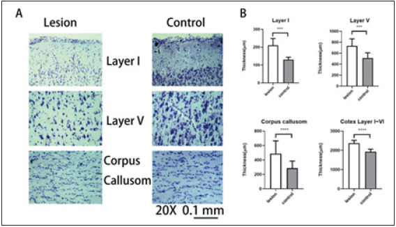
Table 2: Neural damage after stimulation of HFS

HFS: High Frequency Monopolar Stimulation.
Behavior assessment
No rats had visible major or minor seizure activity throughout the course of the study. None of the 12 rats showed abnormal EEG waves before or after stimulation. However, the EEG showed a very deep anesthesia pattern from the general anesthesia of isoflurane. All rats recovered well from anesthesia and exhibited no motor deficit or abnormal behavior within the 5 hours after stimulation and before sacrifice.
Discussion
In this experimental study, we established an animal model
using rats that could simulate the potential brain damage from
HFS. We delivered 100 trains of 100mA HFS to the rat brain. After
stimulation, the brains showed swelling and coloring consistent with
hemorrhage or hemolysis on visual observation. Comparing Nissl,
IBA-1 and DAPI staining from the electrode sites with comparable
regions on the contralateral side, it was found that significant
neural damage was associated with the electrical stimulation. These
results indicate that the cortex may be injured by HFS if a certain
safety threshold is exceeded. The safety threshold for transcranial
direct cortical stimulation is relatively well established but has
not been clearly identified for HFS [13,14,23]. In general, higher
current intensity, total charge and total charge density will augment
neuronal damage to brain tissue [26]. Oinuma et al. [16] established
an animal model and used 1.5~50mA HFS repeated 100 times on
rat sensorimotor cortex [16]. They didn’t observe neural injury on
light microscope. Janca et al. reported using a short sequence of
15 monophasic pulses of HFS up to 100mA with 400μs duration
repeated 5 times on each site of the patients’ brain, which did not
cause disruptive changes on histopathological examination [27].
However, the stimulating electrode for continuous MEP monitoring
is usually placed at one spot with repeated stimulation during the
whole surgical procedure. Whenever current is used to stimulate
brain, it may cause neural injury if the stimulus strength exceeds
a certain level [21,27-33]. Both HFS and LFS were considered at
risk for certain side effects, such as seizure, scalp burns, cardiac
arrhythmia, tongue, or lip laceration [3,13,15,34]. Although HFS
is considered a relatively safe method, some patients, especially
pediatric patients, require a higher current to trigger MEPs [19].
Standard electrical stimulation protocol is ineffective for 20%
of young children [27]. Ng reported that in 10 of 15 cases with
pediatric surgery, 50 to 90 volts were required for direct cortical
stimulation to elicit MEPs [20].
Current intensity under 30mA is usually considered safe in
clinical use, but it is unclear what the safe stimulating threshold
with higher electricity power is for HFS [3,32]. In order to establish
a model, we used 100mA HFS repeated 100 times to observe the
potential neural damage. In our model, we didn’t remove the thin
dura mater because: (1) it is easy to injure the brain when removing
it; and (2) the dura mater of the rat can reduce the gap of arachnoid
membrane between rat and human brain [35]. In this study, the brain
lesion included brain tissue edema, increased extracellular space,
severely damaged neural cells, and hemorrhage, corresponding
with lesions caused by electrical stimulation [21,28]. According
to the grading of neuronal damage as described by Pudenz et al.
[21] and Yuen et al. [28] all the rats had severe neural damage. The
DAPI staining also showed the severe injury of the cell nucleus
[36]. IBA-1 staining revealed ramified or resting microglia on the
control side. In the lesion, the microglia showed dense, spherical
morphology which was consistent with reactive or phagocytic
microglia. In the area of injury, almost all the Iba1 positive glial
cells changed their morphology. Therefore, we didn’t count the
number. It is possible that severe neural damage induced microglial
transformation into brain macrophages to remove dead cells within
5 hours of injury [37,38]. It was unclear whether the lesions can be
completely repaired over time. If the lesion is severe and cannot be
fully repaired, this process may result in glial scars [39]. It remains
to be determined whether the damage we observed is transient or
converts over time to a typical glial scar.
The charge density and charge per phase are neural excitotoxic
cofactors [15,28]. Currently, the safety limits of the HFS technique
applied in a short train over a longer period of time remains
undefined. In this pilot study, the charge of one pulse was 50μC,
and the charge density was 707μC/cm2 pulse, which is very
high compared to clinical standards. Severe neural damage was
observed after 100 trains were delivered within 15 minutes.
This finding demonstrates that repeated HFS at the same site
may have a cumulative effect and is likely to cause severe neural damage. Our study has established a rat model for studying neural
damage caused by short-train HFS. The current parameters, while
exceeding normal clinical standards, caused severe neural damage
to the rat brain that are observable and quantifiable. Although it
may be difficult to apply the safety limits from the animal histologic
changes directly to humans, the neural damage observed may cause
permanent neural damage in human brain that would increase
the potential to induce seizure [40]. The primary effects appear
immediately as a direct result of the tissue or cellular injury, while
the secondary effects may evolve over a longer period as a result of
molecular signaling cascades that are activated by the initial injury.
Longer observation post procedure may help define behavioral
outcomes and whether the changes we observed are transient or
persist and lead to scarring.
Limitations
The purpose of this study was to create an animal model of brain injury caused by direct cortical stimulation with HFS. Therefore, a relatively high current intensity, 100mA, was used to stimulate. The EMG (MEP) was recorded during the experience. However, the latency of the MEP of rat is very short and was overlapped with stimulating artifact, since the same stimulus montage was used as for human. For this reason, we did not include the EMG recordings in our results. Future studies with varying levels of current intensity are necessary to determine the precise threshold above which injury is induced. Additionally, the stimulating parameters in this study were based on settings used for human patients with a larger brain volume and may not directly translate to the smaller rodent brain. The latency of MEPs recorded on rats was very short, so it was difficult to distinguish the MEP response from artifacts. Furthermore, the current study does not explore the long-term effects of the morphological changes induced by the stimulation. Future studies with an extended survival time after stimulation will be needed to determine lasting effects of HFS-induced injury on the brain and behavior once a safety threshold is determined.
Conclusion
This study has established a brain lesion model caused by direct cortical stimulation using HFS on rats. Gross observations, histological and immunohistochemistry methods, such as the Nissl, DAPI and IBA-1 staining were used to identify the injured cells and the phagocytic changes of microglia. Additional experiments are needed to fully define the safety threshold of direct cortical stimulation using short-train HFS, and the model established here can be easily replicated by different investigators attempting to study direct cortical HFS.
Acknowledgment
We thank Jason Leong, for assistance in experimental technology. T.Y., L.G. performed the animal surgery and HFS stimulation. T.Y. performed the staining of the study, performed the imaging, analysed results and prepared the manuscript. T.Y., L.G. and J.S. interpreted and integrated all the data. T.Y., L.G. and J.R. wrote the manuscript with input from all coauthors. All authors approved the final version of the manuscript. L.G., J.R and J.S. supervised the research.
References
- Berger MS, Cohen WA, Ojemann GA (1990) Correlation of motor cortex brain mapping data with magnetic resonance imaging. J Neurosurg 72(3): 383-387.
- Taniguchi M, Cedzich C, Schramm J (1993) Modification of cortical stimulation for motor evoked potentials under general anesthesia: technical description. Neurosurgery 32(2): 219-226.
- Sartorius CJ, Wright G (1997) Intraoperative brain mapping in a community setting technical considerations. Surg Neurol 47(4): 380-388.
- Krombach GA, Spetzger U, Rohde V, Gilsbach JM (1998) Intraoperative localization of functional regions in the sensorimotor cortex by neuronavigation and cortical mapping. Comput Aided Surg 3(2): 64-73.
- Cedzich C, Taniguchi M, Schafer S, Schramm J (1996) Somatosensory evoked potential phase reversal and direct motor cortex stimulation during surgery in and around the central region. Neurosurgery 38(5): 962-970.
- Kombos T, Suess O, Funk T, Kern BC, Brock M (2000) Intra-operative mapping of the motor cortex during surgery in and around the motor cortex. Acta Neurochir (Wien) 142(3): 263-268.
- Horiuchi K, Suzuki K, Sasaki T, Matsumoto M, Sakuma J, et al. (2005) Intraoperative monitoring of blood flow insufficiency during surgery of middle cerebral artery aneurysms. J Neurosurg 103(2): 275-283.
- Kawaguchi M, Sakamoto T, Ohnishi H, Shimizu K, Karasawa J, et al. (1996) Intraoperative myogenic motor evoked potentials induced by direct electrical stimulation of the exposed motor cortex under isoflurane and sevoflurane. Anesth Analg 82(3): 593-599.
- Kombos T, Suess O, Ciklatekerlio O, Brock M (2001) Monitoring of intraoperative motor evoked potentials to increase the safety of surgery in and around the motor cortex. J Neurosurgery 95(4): 608-614.
- Neuloh G, Pechstein U, Cedzich C, Schramm J (2004) Motor evoked potential monitoring with supratentorial surgery. Neurosurgery 54(5): 1061-1070.
- Sakuma J, Suzuki K, Sasaki T, Matsumoto M, Oinuma M, et al. (2004) Monitoring and preventing blood flow insufficiency due to clip rotation after the treatment of internal carotid artery aneurysms. J Neurosurgery 100(5): 960-962.
- Szelenyi A, Kothbauer K, Camargo AB, Langer D, Flamm ES, et al. (2005) Motor evoked potential monitoring during cerebral aneurysm surgery: Technical aspects and comparison of transcranial and direct cortical stimulation. Neurosurgery 57(4): 331-338.
- Bikson M, Grossman P, Thomas C, Zannou AL, Jiang J, et al. (2016) Safety of transcranial direct current stimulation: evidence based update 2016. Brain Stimul 9(5): 641-661.
- Calancie B, Harris W, Broton JG, Alexeeva N, Green BA (1998) Threshold-level multipulse transcranial electrical stimulation of motor cortex for intraoperative monitoring of spinal motor tracts: Description of method and comparison to somatosensory evoked potential monitoring. J Neurosurg 88(3): 457-470.
- McCreery DB, Agnew WF, Yuen TG, Bullara L (1990) Charge density and charge per phase as cofactors in neural injury induced by electrical stimulation. IEEE Trans Biomed Eng 37(10): 996-1001.
- Oinuma M, Suzuki K, Honda T, Matsumoto M, Sasaki T, et al. (2007) High-frequency monopolar electrical stimulation of the rat cerebral cortex. Neurosurgery 60(1):189-196.
- McCreery DB, Agnew WF, Yuen TG, Bullara LA (1988) Comparison of neural damage induced by electrical stimulation with faradaic and capacitor electrodes. Ann Biomed Eng 16(5): 463-481.
- Cedzich C, Pechstein U, Schramm J, Schafer S (1998) Electrophysiological considerations regarding electrical stimulation of motor cortex and brain stem in humans. Neurosurgery 42(3): 527-532.
- Yi YG, Kim K, Shin HI, Bang MS, Kim HS, et al. (2019) Feasibility of intraoperative monitoring of motor evoked potentials obtained through transcranial electrical stimulation in infants younger than 3 months. J Neurosurgery Pediatrics 15: 1-9.
- Ng WH, Ochi A, Rutka JT, Strantzas S, Holmes L, et al. (2010) Stimulation threshold potentials of intraoperative cortical motor mapping using monopolar trains of five in pediatric epilepsy surgery. Childs Nerv Syst 26(5): 675-679.
- Pudenz RH, Agnew WF, Bullara LA (1977) Effects of electrical stimulation of brain. Brain Behav Evol 14(1-2): 103-125.
- Vrba J, Janca R, Blaha M, Jezdik P, Belohlavkova A, et al. (2019) Modeling of brain tissue heating caused by direct cortical stimulation for assessing the risk of thermal damage. IEEE Trans Neural Syst Rehabil Eng 27(3): 440-449.
- MacDonald DB (2002) Safety of intraoperative transcranial electrical stimulation motor evoked potential monitoring. J Clin Neurophysiol 19(5): 416-429.
- Schindelin J, Arganda CI, Frise E, Kaynig V, Longair M, et al. (2012) Fiji: An open-source platform for biological-image analysis. Nat Methods 9(7): 676-682.
- Marsan E, Ishida S, Schramm A, Weckhuysen S, Muraca G, et al. (2016) Depdc5 knockout rat: A novel model of mTORopathy. Neurobiol Dis 89: 180-189.
- Liebetanz D, Koch R, Mayenfels S, Konig F, Paulus W, et al. (2009) Safety limits of cathodal transcranial direct current stimulation in rats. Clin Neurophysiol 120(6): 1161-1167.
- Janca R, Jezdik P, Jahodova A, Kudr M, Benova B, et al. (2018) Intraoperative thermography of the electrical stimulation mapping: A Safety Control Study. IEEE Trans Neural Syst Rehabil Eng 26(11): 2126-2133.
- Yuen TG, Agnew WF, Bullara LA, Jacques S, McCreery DB (1981) Histological evaluation of neural damage from electrical stimulation: considerations for the selection of parameters for clinical application. Neurosurgery 9(3): 292-299.
- Gordon B, Lesser RP, Rance NE, Hart J, Webber R, et al. (1990) Parameters for direct cortical electrical stimulation in the human: histopathologic confirmation. Electroencephalogr Clin Neurophysiol 75(5): 371-377.
- Levi H, Schoknecht K, Prager O, Chassidim Y, Weissberg I, et al. (2012) Stimulation of the sphenopalatine ganglion induces reperfusion and blood-brain barrier protection in the photothrombotic stroke model. PLoS One 7(6): e39636.
- Liu H, Wang Q, Zhao Z, Xie Y, Ding S, et al. (2016) The Clinical and medicolegal analysis of electrical shocked rats: Based on the serological and histological methods. BioMed Research International 4896319.
- Yoshida G, Imagama S, Kawabata S, Yamada K, Kanchiku T, et al. (2019) Adverse events related to transcranial electric stimulation for motor-evoked potential monitoring in high-risk spinal surgery. Spine 44(20): 1435-1440.
- Kawaguchi M, Ohnishi H, Sakamoto T, Shimizu K, Karasawa J, et al. (1996) Intraoperative electrophysiologic monitoring of ocular motor nerves under conditions of partial neuromuscular blockade during skull base surgery. Skull Base Surg 6(1): 9-15.
- Szelenyi A, Joksimovic B, Seifert V (2007) Intraoperative risk of seizures associated with transient direct cortical stimulation in patients with symptomatic epilepsy. J Clin Neurophysiol 24(1): 39-43.
- Costa Ade M, Kobayashi GS, Bueno DF, Martins MT, Ferreira Mde C, et al. (2010) An experimental model for the study of craniofacial deformities. Acta Cir Bras 25(3): 264-268.
- Limoa E, Hashioka S, Miyaoka T, Tsuchie K, Arauchi R, et al (2016) Electroconvulsive shock attenuated microgliosis and astrogliosis in the hippocampus and ameliorated schizophrenia-like behavior of Gunn rat. J Neuroinflammation 13(1): 230.
- Streit WJ, Walter SA, Pennell NA (1999) Reactive microgliosis. Prog Neurobiol 57(6): 563-581.
- Davis EJ, Foster TD, Thomas WE (1994) Cellular forms and functions of brain microglia. Brain Res Bull 34(1): 73-78.
- Fawcett JW, Asher RA (1999) The glial scar and central nervous system repair. Brain Res Bull 49(6): 377-391.
- Mountney A, Boutte AM, Cartagena CM, Flerlage WF, Johnson WD, et al. (2017) Functional and molecular correlates after single and repeated rat closed-head concussion: Indices of vulnerability after brain injury. J Neurotrauma 34(19): 2768-2789.
© 2021 Lanjun Guo. This is an open access article distributed under the terms of the Creative Commons Attribution License , which permits unrestricted use, distribution, and build upon your work non-commercially.
 a Creative Commons Attribution 4.0 International License. Based on a work at www.crimsonpublishers.com.
Best viewed in


.jpg)


 Editorial Board Registrations
 Submit your Article
 Refer a Friend
 Advertise With Us
.jpg)


.jpg)


.bmp)
.jpg)
.png)
.jpg)


.jpg)


.png)

.png)


.png)


