- Submissions

Full Text
Research & Development in Material Science
Evaluation of The Ballistic Impact Behaviors of Metal Alloys-Based Carbon-Fiber/Epoxy Composite Laminates
Aysun Guven Citir1, Serkan Toros2,3, Fahrettin Ozturk1,3*
1Department of Mechanical Engineering, Ankara Yildirim Beyazit University, Türkiye
2Department of Mechanical Engineering, Nigde Omer Halisdemir University, Türkiye
3Turkish Aerospace Industries, Inc., Ankara, Türkiye
*Corresponding author:Fahrettin Ozturk, Department of Mechanical Engineering, Ankara Yildirim Beyazit University, Türkiye
Submission: November 20, 2023;Published: December 01, 2023

ISSN: 2576-8840 Volume 19 Issue 5
Abstract
In this article, the ballistic impact response of multilayered Carbon Fiber-Reinforced Polymer (CFRP) composite laminates supported with metals was investigated using the LS-DYNA explicit finite element software. The hybrid composite laminates were subjected to a high velocity ballistic impact by a round nose projectile. The implemented numerical model has been verified by comparison with the published experimental results of Ti6Al4V. Furthermore, the effect of different metal alloys including Al 2024-T3, Al 7075-T6, Al 6061-T6 and the stacking sequences were studied by using the verified numerical model. The final computational simulation results showed a good correlation with experimental results in terms of the deformation and damages of composite laminates.
Keywords:Ballistic impact; Titanium; Aluminium; Hybrid composite laminates; Ballistic limit velocity (V50)
Introduction
Fiber-Reinforced Polymer Composites (FRPCs) have been widely used due to their outstanding mechanical properties such as high strength, high flexibility, high stiffness, long fatigue life, and low density. However, they have some drawbacks such as relatively low impact strength and low fracture toughness. To overcome these disadvantages, FRPCs were combined with thin metal layers [1-3]. Fiber Metal Laminates (FMLs) consist of thin metal layer and plies of fiber reinforced polymeric materials. By combining these two different materials, the mechanical properties such as fatigue resistance, strength, fracture toughness, impact resistance and energy absorbing capacity can be improved compared to monolithic materials [4]. Moreover, the fatigue crack growth rates in adhesive bonding area of the sheets can be reduced by laminating and adhesively bonding thin sheets unlike thick monolithic sheet [3].
FMLs structures have been manufactured using various metal constituents namely aluminium, magnesium, titanium, and stainless steel [5-8]. Aramid Fiber Reinforced Aluminium Laminates (ARALL), Carbon Fiber Reinforced Aluminium Laminates (CARALL), and Glass Fiber Reinforced Aluminium Laminates (GLARE) are well-known aluminium based FMLs composites. Hoo et al. [9] investigated the ballistic limit and energy absorption of GLARE panels which consist of 2024-T3 aluminium alloy sheets and S2-glass/epoxy laminates subjected to impact by blunt titanium cylinders. They have found that the ballistic limit of GLARE was higher than bare 2024-T3 aluminium alloy. The high velocity impact behavior of aluminium 2024-T3 alloy, Glass Fiber Reinforced Polypropylene (GFPP) and aluminium foam hybrid structure was studied by Villanueva and Cantwell [10]. The impact testing of unidirectional Fiber Metal Laminate (FML)-reinforced aluminum foam sandwich structures indicates that these hybrid materials exhibit specific perforation energies approximately 23% higher than their plain composite counterparts with similar composite volume fractions. So that the integration of unidirectional FML reinforcement enhances the perforation resistance and energy-absorbing capabilities of the aluminum foam sandwich structures compared to plain composite configurations. Kaboglu et al. [11] explored the impact of altering the mechanical properties of the aluminum alloy layer and adjusting the quantity of aluminum alloy and woven Glass Fiber Reinforced Plastic (GFRP) composite layers within FMLs. Additionally, they investigated the degree of adhesion at the metal/ composite interfaces by selecting different surface treatments for the aluminum alloy layers before FML manufacturing. Three different aluminium alloys were used including 6061-O, 6061- T6 and 7075-T6. It showed that elevating the number of layers of aluminum alloy and GFRP composite, consequently augmenting the thickness of the FML, notably improved the impact energy absorption of the FML panels across all three grades of aluminum alloy utilized in the FMLs. Nevertheless, they display certain shortcomings when exposed to higher operating temperatures, and their resilience under challenging environmental conditions may be compromised [12]. Magnesium alloys have been also used in FMLs. Cortes [13] investigated the impact behavior of magnesiumbased FMLs. In their experimental drop-weight impact study, glass and carbon fiber-based AZ31 magnesium FMLs were subjected to impact. The results were compared with earlier impact results obtained from glass fiber-based Al 2024-O aluminum FMLs. The results showed that the Mg/CFRP laminates exhibited significantly higher specific perforation resistance when compared to the Al/ GFRP laminate. Pärnänen et al. [14] studied the impact resistance and impact damage resistance of magnesium and aluminium based FML materials. Al 2024-73 and AZ31B-H24 were chosen as metal material. They have found that the cracking energy of hybrid FMLs is contingent upon the properties of the metal face sheet and the metal layer has a greater impact on the absolute perforation energy than on the Specific Perforation Energy (SPE). Nevertheless, the low stiffness of magnesium alloys necessitates the use of thick sheets in fabrication. Consequently, in terms of specific properties, they may not differ significantly from aluminum alloys. Moreover, their limitations in high temperatures may render magnesium alloys unsuitable for high-performance impact applications, despite their outstanding properties in compression [15]. Stainless steel alloys have been incorporated into FMLs and their absolute energy absorption values and impact behaviors characterized by drop weight tests [16,17]. Although stainless steel alloys exhibit stiffness levels comparable to titanium alloys, their density is higher than that of titanium (Ti) alloys. Additionally, magnesium alloys do not exhibit the excellent corrosion resistance properties of Ti alloys [12].
The impact response of the titanium-based FMLs subjected to the high velocity impact investigated by Chai et al. [18]. The FMLs were consist of Ti6Al4V titanium alloy and plain weave carbon fabric in two different stacking sequences. In addition, they developed Finite Element (FE) model successfully simulated the contact behavior and all experimentally observed damage modes in both the metal and composite layers, confirming its reliability. Sharma et al. [19] studied the impact and damage response of the glass fiber/epoxy and Ti-6Al-4V titanium alloy sheets in four different layups of FMLs which exhibit the same thickness of the total metal layer. They mentioned that the titanium-based FMLs demonstrate lower degrees of permanent deformation, cracking, and delamination, along with reduced opening and spreading, when compared to their aluminum-based counterparts. Nassir et al. [20] examined the impact of varying the thickness of the titanium alloybased fiber metal laminate. The findings indicate that an increase in the composite core thickness leads to higher values of impact force and absorbed energy. Furthermore, the Finite Element (FE) models were developed to predict the laminates’ response under lowvelocity impact loading. They validated these models by comparing the numerical predictions with the relevant experimental results. The impact responses and damage can be affected by many factors such as metal alloy, fiber type, matrix type, the stacking sequence and the layer directions of FMLs [21]. There are also some other studies on the factors affects the impact behavior of FMLs which have been investigated by various researchers and described as follows [22-26].
In this article, the ballistic limit velocity (V50) and the energy absorption results of the Ti6Al4V/carbon fiber/epoxy composite laminates in two different stacking sequences obtained by the simulation were compared with the experimental results in the literature [27] to validate the implemented Finite Element Model (FEM). Furthermore, the ballistic performance of the three types of aluminium alloy (Al 2024-T3, Al 6061-T6 and Al 7075-T6) composite plates with three different types of stacking sequences were simulated by the verified FEM and evaluated the effects of different types of metal alloys and the stacking sequences on the ballistic behavior of the metal alloys-based fiber metal laminates.
Finite Element Modeling
The finite element model described in this section has six different components including Ti6Al4V sheet, Al 2024-T3 sheet, Al 7075-T6 sheet, Al 6061-T6 sheet, carbon-fiber/epoxy (CF/epoxy) composite laminates and the projectile.
Target specifications
One of the configurations of titanium and unidirectional carbonfiber/ epoxy (UD CF/epoxy) hybrid composite laminate shown in Figure 1a. It consists of square laminates, each 125mm long. The first one was titanium has 0.4mm thickness and the second one was carbon-fiber/epoxy composite which has four layers, with one layer having a thickness of 0.45mm. Quadratic elements with 4 nodes (QUAD4) were used for meshing of all the plates including Ti6Al4V sheet, aluminum alloys sheet, and carbon/epoxy composite. As a result of a mesh convergence study by using various mesh size, the mesh sizes for all plates were set to 0.9mm to provide the approximate residual values in the experiment reported in the literature [27]. The meshing of the hybrid composite laminate structure shown in Figure 1b to clearly distinguish each layer of carbon-fiber/epoxy, each layer was given in a different color. The configurations of the simulated hybrid composite laminates showed in Table 1.
Figure 1:a) The geometry model and b) the mesh of the titanium/carbon fiber-epoxy hybrid composite (TI-CF 0.4/B).
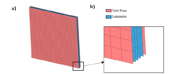
Table 1:Configuration of the simulated hybrid composite laminates.

Projectile specifications
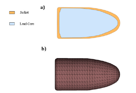
In this study, Hornady bullet (traditional FMJ, item No. 3017) which is the 7.62mm round nose with a weight of 7.1g was used to impact the hybrid composite laminate panels as same in the experiment from Ref. [27]. The 3D model and the mesh of the projectile shown in Figure 2a & 2b, respectively. Tetrahedral elements with 10 nodes (TET10) were selected for meshing for the projectile. The element size is gradually reduced towards the projectile tip region, resulting in a denser mesh at the projectile tip. The projectile impact velocities (V0) were 145m/s, 250m/s and 350m/s.
Figure 2:The projectile a)3D model b) mesh part.
Material model
The metal alloy plates, and the projectile were modeled with the simplified Johnson-Cook plasticity material model:

where y σ is the flow stress, A is the quasi-static yield stress, B is the strain strengthening coefficient, C is the strain rate sensitive coefficient, n is the strain strengthening index, ε is the equivalent plastic strain, and* .ε is a dimensionless strain rate which can be expressed as:

where .ε is each corresponding deformation strain rate and . ε0 is the reference strain rate.
In this material model, temperature variations and cumulative damage of the materials were not considered. However, a nonlinear elastoplastic material model was used for in the most cases where requires the modelling of the impact phenomena on metallic plates. The simplified J-C model constants were listed in Table 2. ENHANCED_COMPOSITE_DAMAGE (MAT 54/55) in LS-DYNA was adopted for UD carbon-fiber/epoxy laminates which is orthotropic material. The SIMPLIFIED_JOHNSON_COOK (MAT 98) in LS-DYNA was used for all metal alloy plates and the projectile. The projectile was modeled as a deformable body, considering the ballistic limit, which is an important parameter for ballistic materials. To simplify the analysis and decrease the computational time, the copper jacket was not considered so that the projectile was modeled as one part [28,29].
Table 2:Material properties and the simplified J-C model constants of Ti6Al4V [30] and aluminum alloys [25,31].

Contact definition
In the ballistic analysis, at least one contact between the bullet and the plate should be defined. However, in this study, a second contact was defined in order to better observe the delamination between the plates. Firstly, in this finite element simulation, the contract algorithm of the AUTOMATIC_SURFACE_TO_SURFACE was adopted to describe the contact between the hybrid panels and the projectile Secondly, the interfaces between hybrid laminate plates were modeled by the AUTOMATIC_SURFACE_TO_SURFACE_ TIEBREAK. The tiebreak failure criterion was determined by:

where σ and S are the stress and strength values, n and s denote the normal and shear directions. In the contact setting options, the NFLS represents the interfacial normal threshold stress and the SFLS represents the interfacial shear threshold stress which are assumed to be 30 and 60MPa, respectively [32].
Boundary conditions
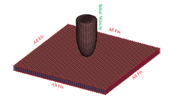
The boundary conditions of the model were simulated similar to the experimental ballistic test setup in the literature [27] as shown in Figure 3. The hybrid composite laminate structures clamped at all the four sides to restrict both translational and rotational motion. Therefore, six degrees of freedom (DOF=6) were fixed at each corner of the plates. The projectile was free at each axis and the initial velocity was defined in z-axis.
Figure 3:The boundary conditions of the FEM.
Validation of numerical models
The implemented finite element model procedure was applied to TI-CF 0.4/B configuration which has the stacking sequence of 0°/45°/-45°/90° from bottom to top with a 2.6mm total thickness to simulate the energy absorption and the ballistic limit velocity and compare them to the experimental results from Ref. [27]. The ballistic limit, V50 was found approximately 250m/s for TI-CF 0.4/B in the simulation as found in the literature [27]. Furthermore, the residual velocities (VR) of the projectile at the different initial impact velocities (V0) calculated by the simulation were compared with the average experimental values from Ref. [27], as shown in Table 3. In simulation, the VR of the projectile for TI-CF 0.4/A and TI-CF 0.4/B FMLs were slightly higher compared to the experimental results which can be caused by the simplifications of the whole FE model. Although there were some deviations, the simulation results were found close to the experimental results. According to Table 3, a good correlation between the experimental from Ref. [27] and FEM results was observed and the errors of the VR under the different initial velocities were between 3.67 % and 5.94 % for TI-CF 0.4/A and TI-CF 0.4/B FMLs. When the initial velocity of the projectile increased, the kinetic energy loss increased. Since, the increase in the initial velocity of the projectile results in an augmentation of the anti-shock capacity [33].
Table 3:Comparison of the experiment and simulation.

Results and Discussion
In this section, the effect of impact velocity of the projectile, stacking sequence and metal type on ballistic impact response of metal alloys-based hybrid composite laminates were investigated using the validated finite element model. The hybrid composite laminates under different impact velocities were investigated (145m/s, 250m/s and 350m/s) for nine different types of fiber metal laminates subjected to the round nose projectile. This section presents the results obtained from the numerical analysis, focusing on the impact resistance, the energy absorption and the failure mechanisms of the metal alloys-based hybrid laminates. Table 4 shows the ballistic impact results for each case. TI-CF 0.4/A and TI-CF 0.4/B configurations shown same penetration behavior as in the literature [27].
Table 4:Ballistic impact simulation result summary.

Impact resistance of the hybrid composite laminates
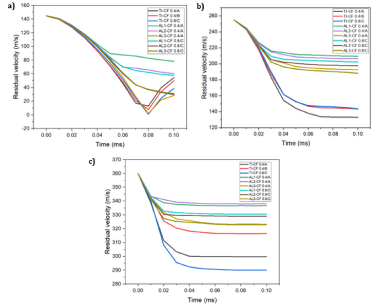
The change curve of the projectile’s velocity of nine different hybrid composite laminates when the initial impact velocities were 145m/s, 255m/s and 360m/s shown in Figure 4. In Figure 4a, the residual velocities of the projectile for the target of TI-CF 0.4/A, TI-CF 0.4/B, TI-CF 0.8/C and AL3-CF 0.4/A plates were started to increase at the moment of 0.08ms because the panels were not perforated and the projectile recoiled. As can be seen from Figure 4b, the residual velocities of the projectile after impact for TI-CF 0.4/A, TI-CF 0.4/B and TI-CF 0.8/C were 133m/s, 143.4m/s and 143.8m/s when the initial impact velocity was 255m/s, respectively. Furthermore, the residual velocities of AL1-CF 0.4/A, AL2-CF 0.4/A and AL3-CF 0.4/A were 209m/s, 206m/s and 192m/s while AL1-CF 0.8/C, AL2-CF 0.8/C and AL3-CF 0.8/C were 202m/s, 197m/s and 188m/s, respectively. For all cases, the residual velocity decreased sharply at the initial stage while it decreased slowly at the moment of 0.03ms for aluminium alloys and 0.06ms for titanium alloys FMLs. It can be concluded from that the plates were penetrated at this moment, and at the moments of 0.05ms and 0.08ms, the velocity of the projectile remains basically unchanged for the aluminium and titanium-based FMLs.
Figure 4:Residual velocity-time graphs for hybrid composite laminates at the impact velocities of a) 145m/s b) 255m/s and c) 360m/s.
Energy absorption capability
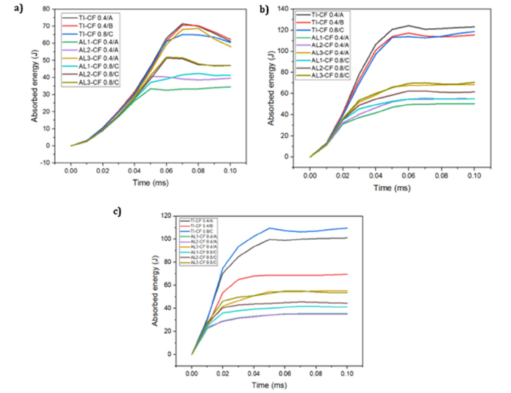
Metal alloys-based fiber metal laminates need to demonstrate the capacity to absorb maximum energy under high-speed impact conditions when applied in military applications. The energies absorbed by nine different hybrid laminates when impacted by round nose projectiles at 255m/s which is the ballistic limit velocity of TI-CF 0.4/B were compared in Figure 5. The energy absorbed by TI-CF 0.4/A, TI-CF 0.4/B and TI-CF 0.8/C plates was 123.10J, 115.48J and 118.68J, respectively. As seen from the figure, TI-CF 0.4/A, TI-CF 0.4/B and TI-CF 0.8/C plates absorbed higher energy compared to aluminium alloys-based hybrid laminates. The titanium-based hybrid laminates showed higher impact resistance compared to aluminium-based hybrid laminates [19,27,34]. In the comparison of aluminum alloy types, hybrid laminates based on Al 7075-T6 demonstrated a greater absorbed energy than those based on Al 2024-T3 and Al 6061-T6. The absorbed energy by AL3- CF 0.8/C and AL3-CF 0.4/A plates were 70.72J and 68.64J, which were the highest among the aluminium alloys-based laminates. AL1-CF 0.4/A had the lowest absorbed energy (ΔE) 50.56J. When the absorbed energy of AL1-CF 0.8/C, AL2-CF 0.8/C and AL3-CF 0.8/C plates compared to TI-CF 0.8/C plate, they showed 53.54%, 48.15% and 40.41% lower than TI-CF 0.8/C plate, respectively. It seemed that the stacking sequences had little influence on the energy absorption of metal alloys-based hybrid laminates under impact load. The absorbed energy of TI-CF 0.4/B was 6.19% lower than that of TI-CF 0.4/A. To compare the stacking sequences of the aluminium alloys-based FMLs, the absorbed energy by AL1-CF 0.8/C, AL2-CF 0.8/C and AL3-CF 0.8/C plates were 8.30%, 10.19 % and 2.93% higher than that of AL1-CF 0.4/A, AL2-CF 0.4/A, AL3-CF 0.4/A plates, respectively. Figure 6 shows the absorbed energy-time graphs for nine different hybrid composite laminates at the impact velocities of 145m/s, 255m/s and 360m/s. It can be concluded that the absorbed energy of the projectile decreased after the 255m/s impact velocity.
Figure 5:Comparison of absorbed energy by nine different types of hybrid composite laminates at the impact velocity of 255m/s.
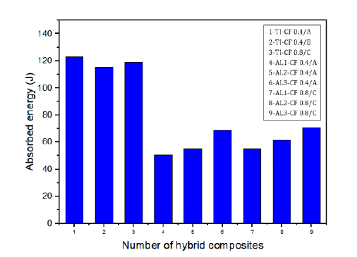
Figure 6:Absorbed energy-time graphs for hybrid composite laminates at the impact velocities of a) 145m/s b) 255m/s and c) 360m/s.
Failure mechanism
Figure 7:a) Indented, b) partially perforated, c) fully perforated and d) penetrated damage modes [27,35].
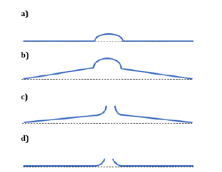
The energy absorption capacity of the hybrid composite laminates was found to be related to the deformation and failure of the samples. There are four types of damage modes shown in Figure 7; [27,35]. In indentation stage, the impact energy is absorbed by the target and only delamination observed with a superficial damage. The perforation stages can be defined as partially perforated and fully perforated. Partial perforation term is used when the sheet has local failures with the fiber breakage and delamination and fully perforated when the sheet has a flexural-tearing failure. When there is a punching failure, it means that penetration occurs.
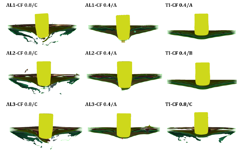
Figure 8 shows the penetrated and not-penetrated hybrid composite laminates under the initial impact velocity of 145m/s. It can be seen that TI-CF 0.4/A, TI-CF 0.4/B and AL3-CF 0.4/A plates were indented at the initial impact velocity of 145m/s. While AL1-CF 0.4/A, AL2-CF 0.4/A and TI-CF 0.8/C plates were partially perforated, AL1-CF 0.8/C, AL2-CF 0.8/C and AL3-CF 0.8/C were fully perforated at the same initial velocity.
Figure 8:Not-penetrated composite laminates and penetrated composite laminates in the same time interval at velocity of 145m/s.
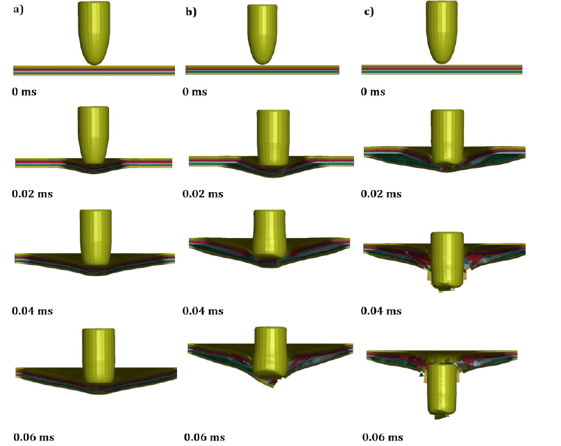
The failure process of TI-CF 0.4/B hybrid composite laminate at the impact velocities of 145m/s, 255m/s and 360m/s shown in Figure 9. From Figure 9a, at the moment of 0.06ms, TI-CF 0.4/B panel was indented at the impact velocity of 145m/s while it was fully perforated at the impact velocity of 255m/s and 360m/s. Furthermore, the projectile tip was deformed over time.
Figure 9:Ballistic impact process of hybrid composite laminates at the impact velocity of a) 145m/s b) 255m/s and c) 360m/s.
Conclusion
In this research, the metal alloys-based hybrid laminate’s reaction to 7.1 round nose projectile has been examined by a means of a numerical analysis using LS DYNA. The absorbed energy, the residual velocities and the ballistic limit velocity of the FML’s have been evaluated and compared for different metal alloys and the stacking sequences. It was found that the impact performance of the titanium-based alloys hybrid composite laminates was much better than that of aluminium-based. The highest absorbed energy was obtained by TI-CF 0.4/A plate 123.10J and AL1-CF 0.4/A plate had the lowest absorbed energy of 50.56J at the velocity impact of 255m/s. Furthermore, the effect of stacking sequences was negligible for all plates.
References
- Serubibi A, Hazell PJ, Escobedo JP, Wang H, Oromiehie E, et al. (2023) Fibre-metal laminate structures: High-velocity impact, penetration, and blast loading - A review. Compos Part A Appl Sci Manuf 173.
- Chai GB, Manikandan P (2014) Low velocity impact response of fibre-metal laminates - A review. Compos Struct 107: 363-381.
- Vogelesang LB, Vlot A (2000) Development of fibre metal laminates for advanced aerospace structures. J Mater Process Technol 103(1): 1-5.
- Sinmazçelik T, Avcu E, Bora MO, Çoban O (2011) A review: Fibre metal laminates, background, bonding types and applied test methods. Mater Des 32(7): 3671-3685.
- Kartikeya K, Chouhan H, Ram K, Prasad S, Bhatnagar N (2022) Ballistic evaluation of steel / UHMWPE composite armor system against hardened steel core projectiles. International Journal of Impact Engineering 164: 1-13.
- Nassir NA, Birch RS, Cantwell WJ, Sierra DR, Edwardson SP, et al. (2020) Experimental and numerical characterization of titanium-based fibre metal laminates. Compos Struct 245: 112398.
- Santhanakrishnan Balakrishnan V, Obrosov A, Kuke F, Seidlitz H, Weiß S (2019) Influence of metal surface preparation on the flexural strength and impact damage behaviour of thermoplastic FRP reinforced metal laminate made by press forming. Compos Part B Eng 173.
- Zhu S, Chai GB (2012) Low-velocity impact response of fibre-metal laminates - Experimental and finite element analysis. Compos Sci Technol 72(15): 1793-1802.
- Hoo Fatt MS, Lin C, Revilock DM, Hopkins DA (2003) Ballistic impact of GLARETM fiber-metal laminates. Compos Struct 61: (1-2): 73-88.
- Reyes VG, Cantwell WJ (2004) The high velocity impact response of composite and FML-reinforced sandwich structures. Compos Sci Technol 64(1): 35-54.
- Kaboglu C (2018) High-velocity impact deformation and perforation of fibre metal laminates. J Mater Sci 53(6): 4209-4228.
- Kazemi ME (2021) Developing thermoplastic hybrid titanium composite laminates (HTCLS) at room temperature: Low-velocity impact analyses. Compos Part A Appl Sci Manuf 149.
- Cortes P, Cantwell WJ (2007) The impact properties of high-temperature fiber-metal laminates. J Compos Mater 41(5): 613-632.
- Pärnänen T, Alderliesten R, Rans C, Brander T, Saarela O (2012) Applicability of AZ31B-H24 magnesium in Fibre Metal Laminates - An experimental impact research. Compos Part A Appl Sci Manuf 43(9): 1578-1586.
- Kazemi ME, Shanmugam L, Yang L, Yang J (2020) A review on the hybrid titanium composite laminates (HTCLs) with focuses on surface treatments, fabrications, and mechanical properties. Compos Part A Appl Sci Manuf 128.
- Boose Y, Kappel E, Stefaniak D, Prussak R, Pototzky A, et al. (2020) Phenomenological investigation on crash characteristics of thin layered CFRP-steel laminates 27(1): 289-298.
- Pärnänen MK, Sarlin E, Saarela O (2015) Debonding and impact damage in stainless steel fibre metal laminates prior to metal fracture. Compos Struct 119: 777-786.
- Chai GB, Manikandan P, Li X (2018) A numerical study on high velocity impact behavior of titanium-based fiber metal laminates. J Compos Sci 2(4): 1-20.
- Sharma AP, Velmurugan R, Shankar K, Ha SK (2021) High-velocity impact response of titanium-based fiber metal laminates. Part I: experimental investigations. Int J Impact Eng 152.
- Nassir NA, Birch RS, Cantwell WJ, Guan ZW (2023) The influence of composite core thickness on the perforation resistance of titanium-based FMLs. Results Mater 19.
- He W (2021) On impact behavior of fiber metal laminate (FML) structures: A state-of-the-art review. Thin Walled Struct 167.
- Jesudoss NR, Vignesh NJ, Winowlin Jappes JT, Velu PS, Barile C, et al. (2022) Effect of stacking sequence of fibre metal laminates with carbon fibre reinforced composites on mechanical attributes: Numerical simulations and experimental validation. Compos Sci Technol 221: 109303.
- Ramadhan AA, Abu Talib AR, Mohd Rafie AS, Zahari R (2012) The behaviour of fibre-metal laminates under high velocity impact loading with different stacking sequences of Al alloy. Appl Mech Mater 225: 213-218.
- Vo TP, Guan ZW, Cantwell WJ, Schleyer GK (2013) Modelling of the low-impulse blast behaviour of fibre-metal laminates based on different aluminium alloys. Compos Part B Eng 44(1): 141-151.
- Seyed Yaghoubi A, Liaw B (2012) Thickness influence on ballistic impact behaviors of GLARE 5 fiber-metal laminated beams: Experimental and numerical studies. Compos Struct 94(8): 2585-2598.
- Andrew JJ, Srinivasan SM, Arockiarajan A, Dhakal HN (2019) Parameters influencing the impact response of fiber-reinforced polymer matrix composite materials: A critical review. Compos Struct 224.
- Sun J, Xu S, Lu G, Wang Q, Gong A (2022) Ballistic impact experiments of titanium-based carbon-fibre/epoxy laminates. Thin-Walled Struct 179.
- Scazzosi R, Manes A, Giglio M (2019) Analytical model of high-velocity impact of a deformable projectile against textile-based composites. J Mater Eng Perform 28(6): 3247-3255.
- Wen Y, Xu C, Wang S, Batra RC (2015) Analysis of behind the armor ballistic trauma. J Mech Behav Biomed Mater 45: 11-21.
- Wang X, Shi J (2013) Validation of Johnson-cook plasticity and damage model using impact experiment. Int J Impact Eng 60: 67-75.
- Sundaram SK, Bharath AG, Aravind B (2022) Influence of target dynamics and number of impacts on ballistic performance of 6061-T6 and 7075-T6 aluminum alloy targets. Mech Based Des Struct Mach 50(3): 993-1011.
- Harper PW, Hallett SR (2010) A fatigue degradation law for cohesive interface elements - Development and application to composite materials. Int J Fatigue 32(11): 1774-1787.
- Tang E, Yin H, Chen C, Han Y, Feng M (2020) Simulation of CFRP/aluminum foam sandwich structure under high velocity impact. J Mater Res Technol 9(4): 7273-7287.
- Li X, Zhang X, Guo Y, Shim VPW, Yang J, et al. (2018) Influence of fiber type on the impact response of titanium-based fiber-metal laminates. Int J Impact Eng 114: 32-42.
- Morinière FD, Alderliesten RC, Benedictus R (2014) Modelling of impact damage and dynamics in fibre-metal laminates - A review. Int J Impact Eng 67: 27-38.
© 2023 Fahrettin Ozturk. This is an open access article distributed under the terms of the Creative Commons Attribution License , which permits unrestricted use, distribution, and build upon your work non-commercially.
 a Creative Commons Attribution 4.0 International License. Based on a work at www.crimsonpublishers.com.
Best viewed in


.jpg)


 Editorial Board Registrations
 Submit your Article
 Refer a Friend
 Advertise With Us
.jpg)


.jpg)


.bmp)
.jpg)
.png)
.jpg)


.jpg)


.png)

.png)


.png)


