- Submissions

Full Text
Research & Development in Material Science
Experimental Simulation of Molten Corium and Sacrificial Material Interaction in a Scaled Down Core Catcher
Samyak S Munot1,2*, Arun K Nayak1,2 and Jyeshtharaj B Joshi1,3
1Homi Bhabha National Institute, Anushakti Nagar, Mumbai 400094, Maharashtra, India
2Reactor Engineering Division, Reactor Design and Development Group, Bhabha Atomic Research Centre, Maharashtra, India
3Department of Chemical Engineering, Institute of Chemical Technology, Maharashtra, India
*Corresponding author: Samyak S Munot, Reactor Engineering Division, Reactor Design and Development Group, Bhabha Atomic Research Centre, Mumbai 400085, Maharashtra, India
Submission: November 08, 2021;Published: November 22, 2021

ISSN: 2576-8840 Volume 16 Issue 2
Abstract
During the severe accident condition involving the core melt, stabilization and cooling the molten corium for long duration is the primary requirement. To address this challenge, core catcher systems are being installed inside the containment of the advanced nuclear reactors. Few ex-vessel core catcher designs incorporate special refractory sacrificial material, which on interaction with molten corium, ablate and reduce the enthalpy of the molten pool. During the interaction, the components of ablated sacrificial material and molten corium are stratified in different layers due to density difference between them, i.e., the low density oxidic components stratify in the top layer while higher density metallic components stratify in the bottom layers in the melt pool. This manuscript presents the material characterization of the stratified melt pool after cooling in an experiment involving interaction of approx. 550kg of molten simulant corium with approx. 150kg of sacrificial material in a scaled down V-shaped ex-vessel core catcher vessel. The cooling strategy in the experiment was similar to prototypic reactor conditions. After cooling and stratification of the melt pool, solid samples from different locations and different heights were collected for SEM-EDS analysis for characterizations. The phenomena of melt inversion were verified in the post-test analysis.
Keywords: Severe accident; Melt inversion; Corium-sacrificial material interaction
Introduction
During the severe accident involving the core melt down (DEC-B) [1], relocation and coolability of the of the molten corium are the most significant issues for reactor safety and accidental management procedures. Especially after Fukushima, the management and mitigation of severe accident have become a design integral part of the advanced reactors. If the molten corium is relocated over the basemat, it may lead to ablation of basemat from where the radioactivity may leak into groundwater. The interaction of molten corium with concrete in the basemat leads to Molten Core - Concrete Interaction (MCCI), which increases the containment pressure due to formation of non-condensable gases like CO, CO2 and Hydrogen by concrete decomposition. This increment in the containment pressure threatens to the integrity of the containment building [2]. Thus, to mitigate the possible consequences of the core meltdown, an ex- vessel core catcher model is proposed to retain and cool the molten corium for prolonged periods [3].
Various experimental and analytical studies were carried out in past to validate the design aspects of core catcher models. During the severe accident scenario, the impact on containment loading due to in-vessel steam explosion, high pressure failure of the Reactor Pressure Vessel (RPV), dynamic combustion, and core melt cooling using core catchers models for PWRs was studied by Kuczera [3]. The QUEOS and PREMIX experimental series were performed to study the effect of In-vessel steam explosion. BERDA experimental program was performed to study the load capacity of Reactor Pressure Vessel.
The melt behaviour after the reactor pressure vessel rupture in
an ex-vessel was studied in DISCO and KAJET tests. As European
Pressurised Reactors (EPR) used special sacrificial material, the
interaction of sacrificial materials with molten corium was studied
by Scholtyssek et al. [4] in KAPOOL, KATS and COMET tests. An
overview of the ex- vessel core melt stabilization on the basis of the
modes of interaction (MCCI and Fuel Coolant Interaction(FCI)),
coolability by bottom flooding and corium retention methodology
for European Union PWR (EU-PWR) were studied by Fishcher et al.
[5-7]. Experiment using the simulant fuel material was performed
to study the coolability and crust formation of the scaled down core
catcher. The prototypic cooling strategy of combination of indirect
cooling top flooding [8] relevant to VVER type core catchers was
used. These studies suggested that ex-vessel core catcher can be
envisaged as the design feature for advanced nuclear reactors as a
severe accident management strategy.
The core catcher contains a special Sacrificial Material (SM) in
which the molten core (corium) falls and causes its ablation along
with melt inversion. The ablation of the sacrificial material due to
molten corium reduces the specific volumetric heat release. The
melt pool is then flooded with water to cool and stabilize it for a
prolonged period [8]. Interaction of the concrete as the sacrificial
material with molten cerium was studied by Seiler et al. [9]. To study
the interaction phenomena in details, Alsmeyer [10] conducted an
experiment with transparent plastic simulating the behaviour of
an oxidic corium melt. HECLA test series [11] showed that dramatic
effects like cracking of concrete due to thermal shock did not take
place. In addition, the maximum ablation depth was limited to
25mm only [11]. Kinetics affecting ablation characteristics for
special concrete and molten corium for EU-APR1400 were studied
by An et al. [12] and found that rate of ablation of concrete
increases with increase in the oxidation of uranium and zirconium.
The ablation of sacrificial material by the ZrO2 jet impingement
was also studied in Verification of Ex-vessel corium STAbilization
(VESTA) test facility [13] at 2775 °C and was observed that the
ablation is based on various factors like corium jet composition,
the degree of superheat, impinging velocity and thermo-physical
properties of melt structures.
Considering the studies mentioned above, it is evident that
the ablation is a very complex phenomenon, which is dependent
on multiple parameters like geometry of the core catcher, the heat
removal mechanism and the interaction of the sacrificial material
with molten corium. To understand the coolability of the core catcher
and the ability to retain the molten corium for a prolonged period,
the experiment needs to be conducted at prototypic conditions. In
view of the above, an experiment has been performed in this paper
to study the stratification of the melt pool after the ablation of the
specific sacrificial material in the ex-vessel core catcher with the
cooling arrangement as that in actual core catcher.
The experiment involved melting of approx. 550kg of simulant
fuel material and pouring it on actual sacrificial materials placed in
simulated core catcher vessel [8]. The cooling strategy adopted was
same as prototypic reactor. Upon cooling and stratification of the
melt pool, the debris samples from different locations and different
depths of the melt pool were collected and analysed.
Experimental Setup and Procedure
Test section details
Due to complexities in using the prototypic reactor materials, a corium simulant material consisting of Cerium Oxide (a surrogate of Plutonium Oxide) and Zirconia, was used in the experiment. This corium simulant material was melted and heated to a temperature of 2500 °C, using the heat of thermite reaction between iron oxide and metallic aluminium. After attaining the temperature, the molten simulant corium is lowered into the V-shaped scaled down core catcher, which is partially filled with sacrificial material (Figure 1). The sacrificial material is combination of fusible oxides like Iron Oxide, Aluminium Oxide and Silica. The core catcher model assembly consists of a scaled down core catcher vessel which is placed in a water tank along with downcomer and shroud plates (Figure 1). The core catcher vessel was mass scaled to a ratio of 1:200 to the prototypic reactor. Approx. 500Kg of molten corium and thermite mixture was melted and poured onto approx. 150Kg of sacrificial material bricks placed in the simulated core catcher vessel.
Figure 1: Schematic of the test section assembly consisting of the thermite melt delivery system and scaled down core catcher and schematic of the core catcher vessel and the test section assembly.
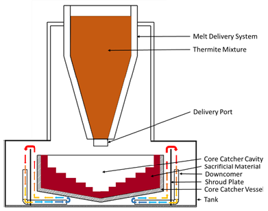
The core catcher vessel, shroud plate and the tank were made of carbon steel. The shroud plate and downcomer arrangement are placed in tank outside the core catcher vessel. This arrangement is used to enhance heat transfer through the outside walls of core catcher vessel by developing a natural circulation loop on either side of the shroud plate and through downcomer. As a severe accident management strategy, initially, the tank is filled with water up to a certain level for indirect cooling and complete flooding takes place after a time delay of 45min from the melt pour. This time delay corresponds to the ablation of sacrificial material and melt inversion due to interaction of molten simulant corium and sacrificial material.
Interaction with sacrificial material
Sacrificial material primarily comprises of fusible oxides of Iron, Aluminium and Silicon. Solid bricks of sacrificial material were fabricated and were arranged in the core catcher vessel cavity in a staggered form (Figure 1) to maximise the area of interaction between sacrificial material and simulant molten corium. As the temperature of the molten corium is nearly 2500 °C, the primary mode of interaction is ablation of sacrificial material. This melting of sacrificial material reduces enthalpy of the overall melt pool. At high temperatures, the metallic component from the molten corium is oxidized upon interact with the oxygen from sacrificial material. During this process, low density oxides are formed which are relocated on the top of the melt pool over the metallic layer, due the higher density of the metallic components. This phenomena of relocation of the low-density oxidic components on the top of the melt pool over the high-density metallic components, is known as melt inversion. Thus, top flooding the core catcher vessel after the melt inversion ensures the relocation of metallic layer to the bottom plenum while a solid crust is formed at the top of the melt pool, which prevents the water ingression into the melt pool and core catcher vessel. As there is no water ingression into the melt pool, the exothermic melt water interaction is prevented along with the hydrogen production due to it. Hence, a strategic time delay of 30 to 45 minutes is observed for melt inversion before complete top flooding the core catcher vessel.
Analysis Methods
Post experiment visual analysis
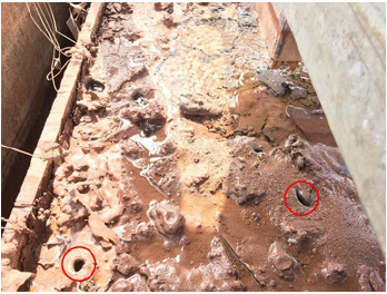
Post experiment visual observation revealed a solid crust formation at the top of the core catcher vessel (Figure 2). This crust was completely adhered to the inner walls of the core catcher vessel, suggesting that there was not water ingression into the melt pool through the sides of the core catcher vessel wall. Although some isolated cavities in the crust were observed having depths ranging from 20mm to 40mm (Figure 2). The thickness crust varied in the range of few centimetres.
Figure 2: Crust formation at the top and water ingression zone at the top up to a depth of about 20 mm.
Density analysis
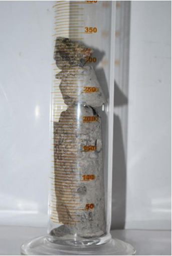
As the melt pool consisted of Alumina, it was predicted that stratified melt pool will be hard ceramic. Thus, a diamond gritted tungsten core drill bit was used to retrieve column samples from different locations (Figure 3). These column samples were further divided vertically to get samples at different height. Each vertically divided samples weighed using precision balance. The volume of the vertically divided samples was measured by submerging them into a water column and measuring the change in volume.
Figure 3: Sample retrieved from the stratified pool after core drilling.
This dividing measured mass by change in volume of the each vertically divided sample gave the density of the each vertically divided sample.
SEM - EDS compositional analysis
A qualitative characterization of the stratified melt pool was
carried out using Scanning Electron Microscopy - Energy Dispersive X-ray Spectroscopy (SEM-EDS) on the vertically divided samples.
Thus, the composition of stratified melt pool at different depths
in the same column position was determined. The EDS technique
determines the elemental composition of the sample by detecting the
characteristic x-rays emitted from the sample due to bombardment
by an electron beam onto the sample. Using this technique, features
or phases as small as 1μm or less can be analysed.
The vertically divided samples were further cut into small
samples having the dimensions of 5mm of length, 5mm of width
and 3mm of depth using the Diamond gritted milling cutting tool.
These samples were then moulded on the conducting mount.
After preparing the sample with conducting mount, the sample
was polished with various grades of sand paper and finally with
diamond polishing to achieve a scratch free surface for better
viewing while SEM-EDS. As the samples are ceramic in nature,
i.e., non- conducting, a sputter coating of gold, having a thickness of
6.8nm, was applied to prevent charging, i.e., trapping of electrons on
the sample surface, thus preventing the extra white regions on the
image formation. This sputter coating provides a channel for the
charging electron to be removed thus enhancing the signal to noise
ratio in SEM imaging.
The gold sputter samples were the placed in the vacuum chamber
of the SEM-EDS and the high-definition SEM images were analysed.
Upon adjusting the focus, the images revealed the features like
feather like structures, needle like structures, fillers and beads in the
samples. The EDS technique is used to determine the composition
of the sample.
The illuminating bright regions in the EDS - SEM images relate
to the presence of the specific element while the quantification
is calculated using X - ray abundance with characteristic energy
curve. The overlapping of the illuminating bright regions of
various elemental presence indicates the formation of the complex
compounds systems.
Results and Discussion
Density analysis
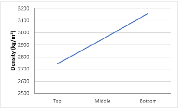
Figure 4 shows the variation in the density of the melt pool along the height inside the core catcher vessel. It clearly indicates that the top plenum has low-density while the bottom layer has highdensity. This can be attributed to the stratification of lower density components in the top plenum over the higher density components in the bottom plenum.
Figure 4: Variation of the density in the stratified core catcher vessel.
SEM-EDS analysis
Using the SEM technique, high-definition images were obtained, which revealed the qualitative feature in which different components of the melt pool are stratified (Figure 5). The EDS - SEM images showed the bright illuminating spots in the characteristic colours, which attributed to the presence of the specific element, while the quantification was carried out using the X-ray technique. The texture of patterns and monochromatic gradation are observed in the image relates to the stratification of different constituents. The overlapping presence of different elements, from illuminating bright spots, indicates the presence of the complex compounds systems. While, no overlapping of different elements indicates the presence of only elemental form and not in any compound. Zirconium Oxide stratifies in the form of billets (Figure 5a), while feather like structures is formed for Error! Reference source not found. mixture of Cerium Oxide and Silica (Figure 5b). The difference in the stratification of aluminium oxide, iron oxide and cerium oxide can be observed by based the porosity and smoothness difference between them (Figure 5c).
Figure 5: Formation of elemental Iron and feather like structure due to combination SiO2 and CeO2.

Top plenum analysis
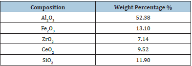
After cooling the simulated core catcher vessel, a solid hard crust was formed at the top of the melt pool. As the density of the top plenum is lower (Figure 4), it was hypostasized that lower density components, like Silica, Alumina and Fe2O3, of the melt pool are stratified in the top plenum. Figure 6 shows the qualitative presence of different elements using EDS-SEM technique at the top plenum of the core catcher vessel. Table 1 shows the quantitative compositional analysis of the melt pool at the top plenum of the core catcher vessel. As the Alumina is the major component of the melt pool (Table 1), it can be considered as the base binding matrix. While Fe2O3 and SiO2 are present in higher amount as compared to ZrO2 and CeO2 in the top plenum of the melt pool (Table 1). The ceramic nature of the crust can be attributed to the presence of oxygen in the melt pool.
Table 1: Compositional analysis of the top plenum of the stratified core catcher.
Note: the maximum acceptable temperature rise based on an average ambient temperature (T∞) of 30 °C during any 24- hour period and a maximum ambient of 40 °C at any time.
Figure 6: SEM-EDS analysis of the top plenum of the stratified core catcher.
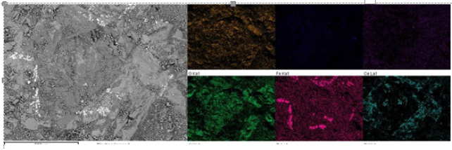
Figure 7 shows the qualitative presence of different elements using EDS-SEM technique at the middle plenum of the core catcher vessel. The quantitative analysis of the melt pool at the middle plenum Table 2 shows increase in the weight percentage of CeO2, SiO2, while decrease in the weight percentage of Al2O3 and Fe2O3. Thus, a higher density in the middle plenum is observed as compared to the top plenum in the core catcher (Figure 4).
Table 2: Compositional analysis of the middle plenum of the stratified core catcher.
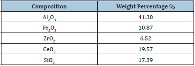
Figure 7: SEM-EDS analysis of the middle surface layer of the stratified core catcher.

Analysis of the bottom plenum of the melt pool showed significant increase in the weight percent of heavy materials like CeO2, ZrO2 in lower plenum (Table 3) as compared to top and middle plenum (Table 1 & 2). Apart from base matrix of Al2O3, CeO2 and ZrO2 form the major component in the lower plenum. Figure 8 shows the qualitative presence of different elements using EDS-SEM technique at the middle plenum of the core catcher vessel.
Table 3: Compositional analysis of the bottom layer of the stratified core catcher.

Figure 8: SEM-EDS analysis of the bottom Surface layer of the stratified core catcher.

The illuminating spot for Iron suggests the presence of Iron, while the dark spot for other elements on the same location suggest the absence of other elements (Figure 9). Thus, it is considered that Iron in its metallic form was observed in the bottommost plenum of the core catcher vessel.
Figure 9: EDS-SEM analysis of bottom plenum.

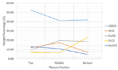
Figure 10 shows compositional analysis variation along the height of the stratified melt pool. Figure 10 shows that, Alumina is the major component (approximately 40% to 50%) in all the heights, specifically more in the top plenum of the stratified melt pool. While, the heavier constituents like ZrO2, CeO2 and Fe metal were stratified towards the bottom plenum of the stratified melt pool. As Alumina is one of the major components of the sacrificial material, it can be assumed that the after the ablation of sacrificial material in prototypic core catcher during severe accident, the Alumina from the sacrificial material will occupy the top most layer and form the solid crust upon melt inversion and stratification. While CeO2, ZrO2 and Fe metal, surrogating material for Fuel and structural material in the prototypic reactor, will be stratified in the inner lower plenum of the melt pool, which is surrounded by core catcher vessel on all side and a thick crust at the top.
Figure 10: Composition analysis over height of the stratified core catcher.
Conclusion
The results confirm the migration of the less dense components of the melt pool, (like Al2O3 and Fe2O3), to the top of the melt pool, while the high dense components of the melt pool (like CeO2, ZrO2 and Fe metal) migrate towards the bottom of the melt pool. This provides a validation of the melt inversion phenomena after ablation of sacrificial material during interaction with fuel. Considering the safety of the reactor, the radioactive fuel along with structural material is vitrified in the bottom plenum of the melt pool. This prevents the escape of the radioactivity into the containment building. As, the metallic component is part of the bottom most layer, due to no water ingression into the core catcher vessel after flooding, the metal water interaction, producing hazardous hydrogen gas, is prevented. Thus, a time delay for melt inversion should be considered as a design aspect for ex-vessel core catcher.
References
- International Atomic Energy Agency (2016) Considerations on the application of the IAEA safety requirements for the design of nuclear power plants. International Atomic Energy Agency, Vienna, Austria, p. 88.
- Mahaffey J (2014) Atomic accidents: A history of nuclear meltdowns and disasters: From the ozark mountains to fukushima. Pegasus Books.
- Kuczera B (1993) Research-and-development activities on safety aspects of future PWR plants performed at Kfk. Nucl Saf 34(2): 213-229.
- Scholtyssek W, Heusener G, Hofmann F, Plitz H (2002) Severe accident related research and development at Forschungszentrum Karlsruhe for present and future needs. Nucl Technol 139(1): 10-20.
- Bechta S (2009) VVER steel corrosion during in-vessel retention of corium melt.
- Fischer A, Herbst O, Schmidt H (2005) Demonstration of the heat removing capabilities of the EPR core catcher. Nucl Eng Des 235(10-12): 1189-1200.
- Fischer M (2004) The severe accident mitigation concept and the design measures for core melt retention of the European Pressurized Reactor (EPR). 11th Int Conf Nucl Energy 230(1): 169-180.
- Munot SS, Kulkarni GVPP, Nayak AK (2019) Experimental Investigation of melt coolability and ablation behavior of oxidic sacrificial material at prototypic conditions in scaled down core catcher. J Nucl Eng Radiat Sci 5: 041206.
- Seiler JM, Labergri F, Froment K, Valin F (2001) Model development for the calculation of corium-ceramic interaction during severe accidents in LWRs. Nucl Eng Des 204(1-3): 401-412.
- Alsmeyer H, Tromm W (1995) Concept of a core cooling system and experiments performed. Nucl Eng Des 154(1): 69-72.
- Sevón T, Kinnunen T, Virta J, Holmström S, Kekki T, et al. (2010) HECLA experiments on interaction between metallic melt and hematite-containing concrete. Nuclear Engineering and Design 240(10): 3586-3593.
- An SM, Ha KS, Min BT, Kim HY, Song JH (2015) Ablation characteristics of special concrete due to an impinging zirconium-dioxide melt jet. Nucl Eng Des 284: 10-18.
- Yeol Kim H, Mo An S, Jung J, Soon Ha K, Ho Song J (2015) VESTA test facility for severe accident researches at KAERI.
© 2021 Samyak S Munot. This is an open access article distributed under the terms of the Creative Commons Attribution License , which permits unrestricted use, distribution, and build upon your work non-commercially.
 a Creative Commons Attribution 4.0 International License. Based on a work at www.crimsonpublishers.com.
Best viewed in


.jpg)


 Editorial Board Registrations
 Submit your Article
 Refer a Friend
 Advertise With Us
.jpg)


.jpg)


.bmp)
.jpg)
.png)
.jpg)


.jpg)


.png)

.png)


.png)


