
- About Us
- Information
-

The Author ensures that the research has been conducted responsibly and ethically with adherence to all relevant regulations. read more..
- For Authors
- For Reviewer
- Manuscript Guidelines
- Membership
- Publication Ethics
-
- Journals
- Reprints
- e-Books
- Videos
- Policies
- Contact Us
 COVID-19
- Submissions


Full Text
Research & Development in Material Science
Investigation of Effects of Material Dimensions on Wrinkling in Flexforming Process
Gurhan Yilgin1,2, Oguzhan Yilmaz2, Fahrettin Ozturk1,3* and Hasan Ali Hatipoglu1
1Turkish Aerospace Industries, Inc., Ankara, Turkey
2Advanced Manufacturing Technologies Research Group (AMTRG), Department of Mechanical Engineering, Gazi University, Turkey
3Department of Mechanical Engineering, Ankara Yıldırım Beyazıt University, Turkey
*Corresponding author: Fahrettin Ozturk, Department of Mechanical Engineering, Ankara Yıldırım Beyazıt University, Turkey
Submission: October 29, 2021;Published: November 05, 2021

ISSN: 2576-8840 Volume 16 Issue 1
Abstract
Sheet metal forming processes are very common manufacturing and leading processes in automotive and aerospace industries. Flexforming is one of the sheet metal forming processes which is preferable due to its flexible manufacturing capabilities and its ability to produce multiple parts simultaneously. Among flexformed parts, convex contoured shaped ones are very common and wrinkling is a characteristic defect for those kinds of parts. Prediction of wrinkling before manufacturing is highly crucial in order to reduce scrap rates, labor time, and other unexpected costs. In this research work, extensive experiments were conducted with convex contoured parts on a flexforming press in order to investigate the effect of geometric parameters on wrinkling. The results have shown that the wrinkling tendency increases with increasing flange length, and with decreasing contour radius, and sheet thickness. The experimental findings are then used to generate wrinkling limit diagrams in which safety and failure zones are specified for the different material conditions and sheet thicknesses. The developed diagrams can practically be used to design defect free parts, reduce scrap rates, and reduce production costs significantly.
Keywords: Flexforming; Sheet forming; Wrinkling; Convex contour flange
Introduction
The fundamental principal of hydroforming process is to apply pressurized fluid to a sheet to form a part [1]. Basically, pressurized fluid is used to form the part and a single die is generally used. In diaphragm forming (or flexforming), which is a special form of hydroforming, a force is produced by pressurizing fluid in a closed circle fluid system and this force is used to form the sheet. In the process, the sheet metal is placed onto a sheet metal die (usually the lower die) and the diaphragm including fluid reservoir is located at top. Then the fluid is pressurized and the diaphragm is moved towards the lower die. When the diaphragm is moved, the sheet is pressed between the diaphragm and the lower die. With the increase of pressure, the elastic diaphragm behaves like the upper die and the sheet metal is drawn into the lower die, completing forming process [2-3].
Flexibility of the diaphragm accommodate multiple parts production due to its behavior like the upper die. For this reason, parts having different shapes can easily be manufactured [4]. Typically, aerospace industry has many different parts at limited quantity. Hereby, this method is widely used [5] and provide great advantages in terms of cost for aerospace industry. Parts produced by flexforming process have better surface qualities than the parts produced by other methods [6]. Besides, the usage of hydraulic pressure instead of the upper die, helps complex and difficult shaped parts production. In a conventional sheet metal forming operation, a die set containing an upper die and a
lower die is needed, whereas in this method, only a lower die is
sufficient. Elimination of the upper die and labor cost savings are
the biggest advantages of the process. Near-net-shape geometry
is almost achieved [7]. Thickness thinning is rather smaller
with respect to conventional method and mostly homogeneous
thickness distribution is obtained [8]. The most common failure
in flexforming is wrinkling for convex contoured parts, which is
developed generally on the flange of the part. The main reason for
wrinkling defect is that the shortening of the flange edge length
after forming, where the greatest compression in the hoop direction
occurs [9].
Hatipoglu et al. [10] investigated the effect of sheet thickness,
die bend radius, flange length, and rolling direction on flanging
of straight and convex contoured AA2024-T3 parts, both
experimentally and numerically. They found that the die radius as
well as the rolling direction both have insignificant effects on the
wrinkling, whereas the flange length and the sheet thickness have
significant effects. Finite element results were in good agreement
with experimental ones. Abedrabbo et al. [11] studied the effect
of contour radius on the wrinkling. They found that an increase in
contour radius decreases wrinkling. Wang et al. [12] determined
a mathematical model that shows the relationship between the
flange length and strain. The results reveal that an increase in flange
length raises wrinkles with a ratio. Sun et al. [13] experimentally
studied the wrinkles occurred in rubber forming of convex shaped
parts with Ti-15-3 material and examined them in finite element
analysis. As a result of the study, they observed that the flange
length and rubber type have an effect on wrinkling. Liu et al. [14]
examined the problem of wrinkling in hydroforming process both
experimentally and numerically. They determined the effect of
material stress and diameter-thickness ratio of parts on wrinkling.
Feyissa [15] investigated the forming cryorolled AA5083 sheet
material by hydroforming. They found out that parts with complex
geometries formed by hydroforming method are more successful
than the parts produced by conventional methods.
In this paper, a wrinkling criteria is established in the form of
Wrinkling Limit Diagrams (WLDs) for convex contoured flanging
of AA2024-O and AA2024-W aluminum alloys. This has not
been studied extensively. It is quite important for applications in
aerospace industry. Experiments are conducted on the flexforming
press and the influence of sheet thickness, flange length and
contour radius on wrinkling are investigated. The aim is to predict
wrinkling prior to the manufacturing and obtain defect free parts.
Materials and Methods
Sheet material properties
The wrinkling phenomenon is dependent on both geometric dimensions and material properties. Tensile tests were performed in order to determine the mechanical properties of AA2024 aluminum alloy for both at -O- and -W- thermal conditions. All the tests were conducted by Zwick/Roell model Z100 machine with a 100mm/ min deformation speed at different orientations. True stress vs. true strain curves for the two conditions were plotted in Figure 1. Mechanical properties such as elastic modulus E, yield strength YS, ultimate tensile strength UTS, elongation e, strength coefficient K, and strain hardening exponent n. obtained from tensile tests are listed in Table 1. Curves in Figure 1 and mechanical properties in Table 1 clearly states that AA2024-W has higher strength than AA2024-O. The wrinkling tendency in convex contoured flanging increases with increasing sheet strength. Therefore, wrinkling for -W- condition is more likely to occur than that for -O- condition.
Figure 1 True stress vs. true strain curves of AA2024-O and AA2024-W.

Table 1: Mechanical properties of AA2024-O and AA2024-W.

Experiments and setup
The purpose of experiments is to determine the effects of material and part geometry on wrinkling and establish a wrinkling criteria based on those experimental findings. Experimental parameters, namely, sheet thickness (T), contour radius (R), and flange length (F) are displayed in Figure 2.
Figure 2 Experimental parameters: sheet thickness (T), contour radius (R), and flange length (F).

The experimental parameters were chosen to be the most effective ones on wrinkling and their ranges were determined by their incidences in aircraft parts designs. AA2024 is the mostly used material for flexformed parts and parts are formed either in O, or W condition. Therefore, both AA2024-O and AA2024-W were used in the experiments. Bending radius, which is known to be ineffective in wrinkling, is kept constant (6mm) throughout the experiments. Experimental parameters and their values are summarized in Table 2.
Table 2: Experimental parameters and their values.

Figure 3 shows experiments configuration. There were 2 different materials tested in 4 different thicknesses, 5 different contour radiuses, and 3 different flange lengths. In total, 120 specimens were formed in the experiments.
Figure 3 Experiments configuration: sheet thickness (T), contour radius (R), and flange length (F).

Experimental setup is shown in Figure 4a. A single die was designed and manufactured for the experiments. This die was capable of forming all of the configurations in 24 runs (2 material x 4 thickness x 3 flange length). The die is placed onto the tray of flexforming press without fixing since high pressures prevent movement. Specimens are attached on this die by the help of guide pins and then formed. All experiments were conducted at 70MPa forming pressure with a constant oil temperature of 45 °C, in 34 °C ambient temperature. The total duration of forming process took about 3 min. and the part was exposed to maximum pressure for 3s.
Figure 4b shows the formed specimens after forming process.
Figure 4 Experimental Setup: a) Specimens are attached onto the die with fixing pins and the die is placed on the tray of the press b) Formed specimens on experimental setup.

Results and Discussions
After conducting experiments, wrinkling defect is observed in some configurations with changing numbers and sizes. Figure 5 shows one of those configurations (AA2024-W material, 1.27mm thickness, 125mm contour radius, and 40mm flange length) which results in two wrinkle formations. The size of a wrinkle can be measured by two parameters which are height t, and width w (Figure 6). After performing the 24 runs, wrinkle sizes were measured and tabulated in Table 3. Some samples could not be measured due to their crushed forms. For better visualization, the flange edges of specimens were drawn on plots in figure. Those plots clearly show the effects of experimental parameters on wrinkling.
Figure 5 A formed specimen sample with wrinkling defect (material: AA2024-W, thickness: 1.27mm, contour radius: 125mm, flange length: 40mm).

Figure 6 Schematic view of wrinkle dimensions.

Table 3: Wrinkling measurements.

Figure 7 shows the effect of sheet thickness on wrinkling. As the sheet gets thicker, the number of wrinkles decreases, the size of wrinkles gets bigger, and they disappear eventually. Wrinkling phenomena can be thought as a sort of buckling in which thicker structures resist more.
Figure 7 Effect of sheet thickness on wrinkling (material: AA2024-W, flange length: 30mm, contour radius: 125mm).

Figure 8 shows the effect of flange length on wrinkling. Number of wrinkles increases as the flange length is increased. The reason behind this trend can be explained by considering the arc length of flange edge before and after forming. Before forming, in which the part was flat, the arc length of flange edge was higher than in its final form. As flange length increases, this difference gets higher in which more material is forced to take the final shape, resulting more compressive stresses and more wrinkle formations inevitably.
Figure 8 Effect of flange length on wrinkling (material: AA2024-O, thickness: 0.63mm, contour radius: 125mm).

Figure 9 shows the effect of contour radius on wrinkling. As contour radius gets larger, wrinkle severity decreases. Again, the reason can be explained by referring to previous discussion about the change in arc length of flange edge before and after bending. The change becomes insignificant as contour radius gets larger, converging zero in straight bending, which is wrinkle-free.
Figure 9 Effect of contour radius on wrinkling (material: AA2024-O, thickness: 0.63mm, flange length: 40mm).

Figure 10 shows the effect of thermal condition of AA2024 alloy on wrinkling. The -W- condition, which has higher strength, forms a large wrinkle, whereas -O- condition has no wrinkles. The -Ocondition is brought to -W- condition with solution heat treatment, in which material hardens in the form of smaller grains causing less movement and increase in wrinkling tendency. The results have shown that the wrinkling tendency increases with increasing material strength, and flange length; and with decreasing contour radius, and sheet thickness.
Figure 10 Effect of alloy condition on wrinkling (thickness: 1.60mm, flange length: 40mm, contour radius: 125mm).

After evaluating experiment results, a wrinkling criterion is established in the form of Wrinkling Limit Diagrams (WLD). These diagrams will provide safety and failure zones for a given geometry and material. Figure 11 shows a sample WLD for AA2024-O, 0.63mm. The abscissa is contour radius, and the ordinate is flange length. Experiment results were plotted as dots. When sorted those dots as wrinkle - no wrinkle, a wrinkling limit curve may be fitted. The region above this curve is failure zone, and below is safety zone. This curve could be defined mathematically as:
Figure 11 Wrinkling Limit Diagram (WLD) for 0.63mm thickness AA2024-O.

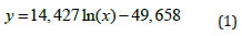
This equation can be used to find wrinkling results of different configurations and is also useful for configurations not found in the experiments. Similar diagrams were drawn for all the other materials and thicknesses.
Conclusion
In this study, the wrinkling defect of convex contoured parts in
flexforming process was investigated experimentally. Aluminum
alloy conditions, sheet thicknesses, contour radiuses, and flange
lengths were considered as experimental parameters. Following
results were drawn:
1. Sheet thickness was very effective on wrinkling. As the
sheet thickness is increased, the wrinkling tendency is reduced
significantly.
2. Contour radius of the bend was another effective parameter. As the contour radius is increased, wrinkle sizes
get smaller, and when further increased, wrinkles disappear
eventually.
3. Increasing flange length contributes to material
thickening, therefore increases the risk of wrinkling.
4. Wrinkling also depends on material strength. Higher
strength materials have higher wrinkling tendency.
5. Some combinations of experimental parameters provide
wrinkle-free parts. Those results are used to generate wrinkling
limit diagrams in which safety and failure zones are separated
by a curve. At the end, those wrinkling limit diagrams can be
used as a check tool by the designer.
References
- Vahl M, Hein P, Bobbert S (2000) Hydroforming of sheet metal pairs for the production of hollow bodies. Rev Met Paris 97(10): 1255-1263.
- Sala G (2001) A numerical and experimental approach to optimise sheet stamping technologies: part II - aluminium alloys rubber-forming. Materials and Design 22(4): 299-315.
- Davidson A (2016) Handbook of precision engineering, vol 10. Macmillan International Higher Education: 2016.
- Ramezani M, Ripin ZM (2012) 1 - Introduction to sheet metal forming processes. In Rubber-Pad Forming Processes, Ramezani M, Ripin ZM, (Eds.), Woodhead Publishing, UK, pp: 1-22.
- Kumar A, Kumar S, Yadav D, Bhu I (2014) In Review of rubber-based sheet hydro-forming processes. Internatuinal All India Manuf Technol Des Res Conf, pp: 1-5.
- Kulkarni S, Ruiwale V, Jadhao M, Kadam A, Kale S (2017) A review on hydroforming processes. International Journal of Current Engineering and Technology, pp: 160-163.
- Bakhshi-Jooybari M, Gorji A, Elyasi M (2012) Developments in sheet hydroforming for complex industrial parts. In Metal Forming - Process, Tools, Design, Kazeminezhad M (Ed.), Intech Open 3: 55-84.
- Önder E, Tekkaya AE (2008) Numerical simulation of various cross sectional workpieces using conventional deep drawing and hydroforming technologies. International Journal of Machine Tools and Manufacture 48(5): 532-542.
- Lee M, Kim C, Pavlina E, Barlat F (2011) Advances in sheet forming-materials modeling, numerical simulation, and press technologies. Journal of Manufacturing Science and Engineering 133(6).
- Hatipoğlu HA, Polat N, Koksal A, Tekkaya AE (2007) Modeling flexforming (fluid cell forming) process with finite element method. Key Engineering Materials, Trans Tech Publ, pp: 469-476.
- Abedrabbo N, Zampaloni MA, Pourboghrat F (2005) Wrinkling control in aluminum sheet hydroforming. International Journal of Mechanical Sciences 47(3): 333-358.
- Wang CT, Kinzel G, Altan T (1995) Failure and wrinkling criteria and mathematical modeling of shrink and stretch flanging operations in sheet-metal forming. Journal of Materials Processing Technology 53(3-4): 759-780.
- Sun YN, Min W, Wu XD (2013) Wrinkling prediction in rubber forming of Ti-15-3 alloy. Transactions of Nonferrous Metals Society of China 23(10): 3002-3010.
- Liu G, Peng J, Yuan S, Teng B, Li K (2015) Analysis on critical conditions of sidewall wrinkling for hydroforming of thin-walled Tee-joint. International Journal of Machine Tools and Manufacture 97: 42-49.
- Feyissa FT, Kumar DR (2019) Enhancement of drawability of cryorolled AA5083 alloy sheets by hydroforming. Journal of Materials Research and Technology 8(1): 411-423.
© 2021 Fahrettin Ozturk. This is an open access article distributed under the terms of the Creative Commons Attribution License , which permits unrestricted use, distribution, and build upon your work non-commercially.
Editor In Chief


.jpg)


Signup for Newsletter

Quick Links
 Editorial Board Registrations
 Submit your Article
 Refer a Friend
 Advertise With Us
Our Recent Edition

.jpg)


Top Editors


.jpg)


.bmp)
.jpg)
.png)
.jpg)


.jpg)


.png)

.png)


.png)


Financial Support

Sponsors

Latest e-Books

Latest Video

 a Creative Commons Attribution 4.0 International License. Based on a work at www.crimsonpublishers.com.
Best viewed in
a Creative Commons Attribution 4.0 International License. Based on a work at www.crimsonpublishers.com.
Best viewed in