- Submissions

Full Text
Research & Development in Material Science
An Experimental Study on Physical Properties of Optimized Sintered Wick Structured Heat Pipe using Computational Fluid Dynamics Analysis Method and Additive Manufacturing Method
Vikneshwaran* and Sobana Raj Kumar
Faculty of Engineering, SEGi College, Malaysia
*Corresponding author: Vikneshwaran, Faculty of Engineering, SEGi College, Malaysia
Submission: April 15, 2021;Published: April 22, 2021

ISSN: 2576-8840 Volume 15 Issue 1
Abstract
This paper reports the techniques of additive manufacturing method applied using rapid prototyping technique for optimized sintered wick structured heat pipe. The structural design of the heat pipe was executed using CATIA V5 computer aided design software. Upon designing, finite element analysis conducted to evaluate performance of heat pipe were evaluated using ANSYS R19 computer aided manufacturing software. The physical properties of heat pipe evaluated according to physical parameters such as Temperature, Pressure and Velocity. Finally, the heat pipe was printed using 3-Dimensional printer. The results obtained achieved the objectives. A low-cost solution identified for the problem stated.
Keywords: Heat Transfer; Physical properties; Computational fluid dynamics; Additive manufacturing
Introduction
Introduction to aluminium and heat pipe
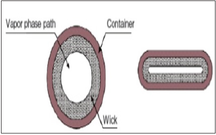
Aluminium Alloy has highly opted for structural applications. 7075 grades has been a mutual choice of raw material selection for heavy-duty manufacturing sectors and construction industries. The advantages are low density, highest tensile strength, ductile and huge fatigue resistant [1]. Heat pipes known as passive equipment. It affords the capacity to transform heat efficiently from one point to another with minimum scale in temperature. A heat pipe is a “double phase” heat transfer mechanism with extremely huge “effective” thermal conductivity. A thin-walled pipe with an internal wick structure allows boiling and condensing to occur within the pipe resulting in heat transfer from the hot end to the cooled end [2]; (Figure 1).
Figure 1:Shows the cross-section of heat pipe [1].

Wick structure
It is a porous structure made of materials like steel, aluminium, nickel or copper in various ranges of porous sizes. The prime purpose of the wick is to generate capillary pressure to transport the working fluid from the condenser to the evaporator. It must also be able to distribute the liquid around the evaporator section at any area where heat is likely to be received by the heat pipe [2]; (Figure 2).
Figure 2:Shows the fundamental sintered wick structure design heat pipe [1].
Literature Review
Simulation and CFD analysis of heat pipe with different wick geometry using CFX
Miniature cylindrical metal powder sintered wick heat pipe
(sintered heat pipe) undoubtedly a unique component with
extreme thermal efficiency for high heat flux electronics cooling.
This paper reports about Heat pipe designed using Wick geometry
0.5mm, 0.75mm, 1mm.The shapes involved are Sintered, V-Groove,
and Screen Groove.
For the Heat pipe, the material chosen was silica material.
Furthermore, nickel alloy nisil (nickel + silicon) applied as a wick
material. Water, Methanol, Aqueous Methanol applied as working
fluids. Numerical evaluations accomplished using CFX (the CFD
solver program). Results provided in graphical representation.
Main objective of this research is to study the difference between
temperature gradient vs heat transfer coefficient with different
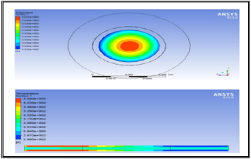
wick’s, wick shapes and different working fluids [3]; (Figure 3).
Figure 3:Contours of sintered wick heat pipe using CFD method [3].
CFD analysis of axially wicked heat pipe
Compared with conventional heat pipes, huge heat transfer rates with improved cooling possibly achieved by Axial Wicked Heat Pipes (AWHP). This exists due to increase in heat transfer area. Experiments conducted to examine the effect of variation in heat input and inclination angle during performance of AWHP. SS304 opted as the material for container and water as the working fluid for AWHP. Interior phase of the outer pipe covered with single layer of screen mesh wick. Surface and vapour temperatures were determined for various heat inputs and inclination angles at steady state conditions and isothermal characteristics of AWHP considering uniform heating application identified. Results proves that increase in heat input, the vapor temperature difference between the evaporator and condenser section decreases for all inclination angles of AWHP. The temperature difference between the evaporator and condenser end in axial direction is the least for vertical position of AWHP at all levels of heat input. This depicts the isothermal characteristic of concentric annular heat pipe. Thermal resistance decreased possibly due to enhancement in nucleate boiling activity, and this improved the heat transfer with increase in heat input. Least thermal resistance found at vertical position of AWHP [4].
Additive manufacturing
Additive Manufacturing (AM) known as renown manufacturing
technique among manufacturing industries. The entire process
speaks about transformation of components from prototypes to
functional structures. Even though its manifest complex parameters,
but still revolutionizing various core manufacturing sectors
such as in aerospace engineering, automobile engineering, semiconductor
and biomedical engineering. Additive manufacturing
is distinguished from traditional manufacturing techniques, such
as casting and machining, due to the technology of constructing
complicated structural design ergonomically without the typical
waste.
Among versatile additive manufacturing methods, 3D printing
Fused Filament Fabrication (FFF) whereby it uses thermoplastic
polymers demands less melting temperature and rapid solidification
rate widely adopted for the convenience of the method. The
advantages are cost efficiency and reduction of waste material.
According to this experiment, an improvised PLA-based polymer
(PLA 3D850) and graphene nanoplatelet reinforced PLA composite
(PLA-Graphene) filaments utilised to manufacture various samples
using FFF technique with a low-cost desktop 3D printer.
Initially, the experimental methodology implemented is briefly
summarized with specific emphasis on samples preparation, the
3D printing procedures, and the experimental set-up. Followed by
the core results obtained from the experiment were summarized.
The outcomes of the different process parameters described about
mechanical performance, accuracy of dimension and textures
are highlighted. At last, conclusions and elevations from this
experiment are outlined [5,6].
Problem Statement & Objectives
Problem statement
Producing an optimized heat pipe prototype conventionally leads to high cost in terms of fabrication and features installation. Conventional testing method to analyze the physical properties turns challenging to obtain accurate and precise results in short period according to finite element method.
Research objectives
A. To design an optimized sintered wicked 3-Dimensional
heat pipe using CAD Software.
B. To analyze the physical properties of the designed heat
pipe using finite element method with simulation software to
prevent from spending huge cost.
C. To conduct simulation, study the impacts of physical
properties such as Temperature, Pressure and Velocity of the
optimized heat pipe.
D. To conduct rapid prototyping method for the optimized
sintered wick pipe using 3-Dimensional printer with Polylactic
Acid (PLA) Layer Filament.
Methodology
Design of sintered wicked heat pipe
To achieve the first objective, an optimized sintered wicked heat pipe designed using CatiaV5 software. Figure 4 was referred to design. The designed heat pipe consists numerous chamfers and curves due to ensure a smooth flow of fluid and pressure (Table 1) ; (Figures 5 & 6).
Table 1:Tabulation of dimensions for designed sintered heat pipe.
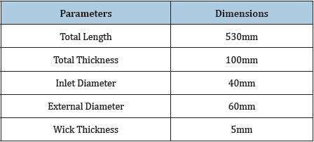
Figure 4:Reference of 3-dimensional basic sintered wicked heat pipe [3].
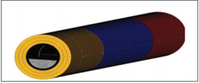
Figure 5:Isometric view of optimized sintered wick heat pipe.
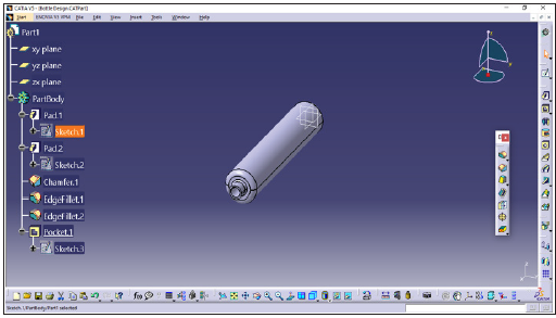
Figure 6:3-Dimensional views of designed heat pipe.
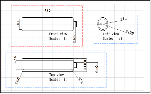
Chronology of finite element analysis
To achieve the second objective, finite element analysis conducted using ANSYS R19 software. Fluent analysis method chosen to proceed the analysis. Initially, the design was loaded in the geometry database. Upon loading, the data updated (Figure 7). Meshing process generated to capture entire elements involved in evaluation. In prior of meshing, the elements were labelled as Inlet and Surface (Figure 8). Meshing process successfully accomplished whereby entire finite elements are captured and eligible for evaluation (Figure 9). At setup database, Energy icon activated. At create and edit materials icon selected the desired materials for the applied geometry design. Aluminum (al) was selected. Converted the material type to solid and followed by filling the properties column according to given data (Tables 2-6); (Figures 10-14).
Table 2:Tabulation of specifications for heat pipe.

Table 3:Tabulation of applied specifications for fluid properties.

Table 4:Tabulation of specifications for external wall surface of heat pipe.

Table 5:Tabulation of maximum temperature at inlet.

Table 6:Tabulation of applied velocity at inlet.

Figure 7:Heat pipe design in geometry database.

Figure 8:Surface capturing and labelling at mesh database.
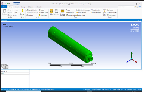
Figure 9:Meshing process successful.

Figure 10:Database of create/edit materials with specifications for heat pipe surface.
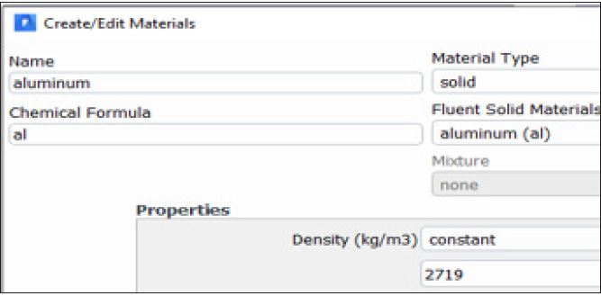
Figure 11:Database of create/edit materials with specifications for fluid.
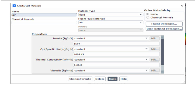
Figure 12:Database of create/edit materials with specifications for external wall.

Figure 13:Database of velocity inlet.

Figure 14:Database of inlet.

Analysis method
Upon completion of data applications, proceeded to solution process to evaluate. Determined the level of iterations at 480 to evaluate the computational fluid dynamics solutions. As per increase in iterations well noticed the changes occurs in simulation of graph during the calculations in progress. As the calculations accomplished, clicked the contours icon to view the 3-Dimensional results upon simulation. Selected the named surfaces and click Save/Display to obtain the output (Figure 15).
Figure 15:Result of mesh contour upon analysis.

Additive manufacturing method
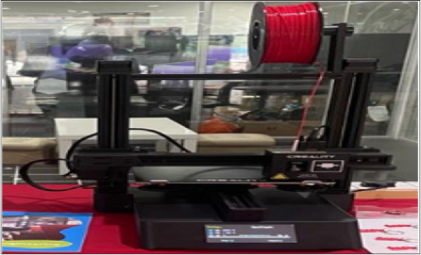
A 3-D Printer branded as ‘CREALITY’ used for additive manufacturing method of optimized sintered wick pipe. This 3-D printer reads ‘stl’ format files of converted CAD Design to print any form of solid model. The structural material used for printing is known as layer filament. The filament is normally belonging to a polymer grade. The layer filament used to print this optimized sintered wick heat pipe is Polylactic Acid (PLA) filament in red colour (Figure 16).
Figure 16:Shows 3-D printer used for rapid prototyping.
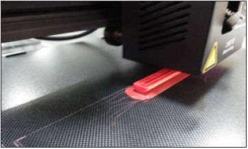
Initially, the CAD Design file of optimized sintered wick heat pipe were converted to ‘stl’ file format. Upon converting, the file was loaded into ‘CREALITY’ slicer software. The software embeds the design according to required dimension and position axis of printing. For optimized sintered wicked heat pipe, Y-axis horizontal position was fixed to execute the printing process. The advantage of this method is the heat pipe was created with a basement to avoid turbulence or deformation due to less rigidity. The crucial part of this experiment is the thermal parameters setting. The maximum allowable temperature is 200deg C° to execute the printing process. Moreover, the maximum duration taken to accomplish the rapid prototyping is about 33 minutes. The reality slicer software reordered geometry of the pipe in mm unit (Table 7) ; (Figures 17 & 18).
Table 7:Tabulation of parameters for 3-d printing.

Figure 17:Shows display of parameters.
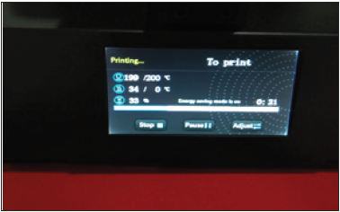
Figure 18:Shows ongoing 3-D Printing process.
Result & Discussion
Velocity impact in heat pipe
According to my third research objective, the analysis conducted to test the thermal characteristics of heat pipe. The velocity rate at 100m/s has resulted as per Figure 19 below. From observation, I noticed that concentration of heat is high at the bottom surface known as Evaporation section. The simulation result at vapor phase path is reddish contour at evaporation section and finally changes into blue at the condensing section.
Figure 19:The cross-section of resultant heat pipe [1].
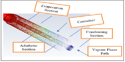
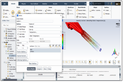
Therefore, it’s understood that the velocity applied at the bottom vapor phase path increased the pressure of hot air at the evaporation section and performs the heat distribution slowly from evaporation stage to medium cooled stage at adiabatic section which is green contour and finally to blue contour at condensing section. Finally, the blue contour states that the hot fluid has become cold as per the role of heat pipe (Figures 19 & 20).
Figure 20:Contour result of applied velocity rate.
Pressure impact in heat pipe
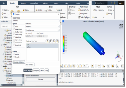
As per observation from Figure 21, the overall pressure contour concludes that, the heat is uniformly distributed. Because the contour at evaporation section is green and slowly turns, light blue at adiabatic section and finally becomes dark blue contour at the condensing section. As the surface area of container is larger compared to vapor phase path, the air particles collide smoothly. This shows the atmosphere is warm at the interior surface of container even though the vapor path is still hot. As the pressure level is not harmful, it prevents the structure from cracking or fractured.
Figure 21:Contour result of pressure flow in heat pipe.
Temperature distribution in heat pipe
According to temperature distribution analysis in Figure 22, the heat pipe has successfully transferred the hot vapor to condensed fluid. The statement a thin-walled pipe with an internal wick structure allows boiling and condensing to occur within the pipe resulting in heat transfer from the hot end to the cooled end proved again in this simulation f1].
Figure 22:Contour result of temperature distribution in heat pipe.

The distribution of heat is smooth as witnessed clearly. It shows the vapor phase path carries good thermal conductivity, which results in good thermal efficiency. The adiabatic process turns successful, by compressing the heat at adiabatic section and convert it to condensed air turned fluid. Aluminium material been a right choice for the pipe construction due to prove its tendency to withstand the applied temperatures from 100 °C / 373K until 300 °C / 573K.
Output of additive manufacturing
According to Figure 23, the outcome of 3-D printing has successfully accomplished. The PLA layer filament has successfully formed the heat pipe without any deformation or geometrical error. As per observation, there is no crack or foreign material were spotted along the structure. This has resulted in positive sign.
Figure 23:Final output of successfully printed heat pipe.

Conclusion
Predominantly, I would confidently mention that the research
objectives achieved without any technical flaw. Computational
Fluid Dynamics (CFD) method to conduct Finite Element Analysis
turned successful. Results obtained for optimized heat pipe are
according to standard specifications and parameters. Through
the results, I witnessed that the tendency of physical properties
such as Temperature, Pressure and Velocity precisely evaluated in
numerical values using CFD method. The references in literature
reviews helped more in conducting the methodology. The output
of simulations proved that CFD simulations are unique and reliable
to explain the performance of prototypes applies thermodynamics
theories and applications. Additionally, additive manufacturing is
concerned as a productive and cost-efficient manufacturing method
to conduct an experimental study.
To conclude my research, I endorse that heat pipe is unique
invention to learn thermal characteristics of a heat transfer
mechanisms. The effect of core elements during heat transfer such
as conduction, convection and condensation are well investigative,
through simulations of heat pipe under different conditions. These
measures provide more advantages to improve the sustainability of
a heat pipes in future with more added features.
References
- Pickens JR (1990) High-strength aluminum P/M alloys. Heat Treating 4: 841-879.
- Nemec P (2018) Porous structures in heat pipes. Porosity Process, Technologies and Applications. UK.
- Naveen KC, Kumar PV, Kumar KD (2015) Simulation and CFD analysis of heat pipe with different wick geometry using CFX. 5(3): 210-213.
- Student MT, Kanth AR (2017) CFD analysis of axially wicked heat pipe. 5(3): 6416-6424.
- Caminero MÁ, Chacón JM, García PE, Núñez PJ, Reverte JM, et al. (2019) Additive manufacturing of PLA-based composites using fused filament fabrication: Effect of graphene nanoplatelet reinforcement on mechanical properties, dimensional accuracy and texture. Polymers 11(5): 799.
- Paneliya S, Prajapati P, Patel U, Trivedi I, Patel A, et al. (2019) Experimental and CFD analysis on heat transfer and fluid flow characteristic of a tube equipped with variable pitch twisted tape. E3S Web of Conferences 116(9).
© 2021 Vikneshwaran. This is an open access article distributed under the terms of the Creative Commons Attribution License , which permits unrestricted use, distribution, and build upon your work non-commercially.
 a Creative Commons Attribution 4.0 International License. Based on a work at www.crimsonpublishers.com.
Best viewed in


.jpg)


 Editorial Board Registrations
 Submit your Article
 Refer a Friend
 Advertise With Us
.jpg)


.jpg)


.bmp)
.jpg)
.png)
.jpg)


.jpg)


.png)

.png)


.png)


