- Submissions

Full Text
Research & Development in Material Science
Blood Flow Analysis Inside A Stenotic Artery Using Power-Law Fluid Model
R Nasrin*, Amzad Hossain and I Zahan
Department of Mathematics, Bangladesh University of Engineering and Technology, Bangladesh
*Corresponding author: R Nasrin, Department of Mathematics, Bangladesh University of Engineering and Technology, Bangladesh
Submission: March 13, 2020; Published: April 03, 2020

ISSN: 2576-8840Volume 13-Issue 1
Abstract
This paper is devoted to study numerically a recent development of a non-Newtonian blood flow model for a stenosed artery in human blood vessel. For numerical investigation the blood flow modeling method of this research begins with non-Newtonian power-law model. The governing system of equation based on incompressible Navier-Stokes equations with externally imposed magnetic resonance has been generalized to take into account the mechanical properties of blood. The intent of this research is to examine the effects of inlet velocity and imposed magnetic field on the blood flow throughout the artery. The Galerkin’s weighted residual method of finite element system has been employed to resolve the governing system of equation with proper boundary conditions. The numerical simulation has been conducted for various inlet velocities from 0.005 to 0.1m/s and magnetic field strength from 0 to 6 tesla with superior convergence of the iterative structure. Results have been shown in terms of velocity, surface plot of velocity, pressure and viscosity contours. Cross-sectional plots of velocity and viscosity magnitudes across the stenotic contraction have also been displayed graphically. Obtained results of the blood flow simulations indicate that viscosity increases due to increasing values of inlet velocity of blood and magnetic strength.
Keywords: Non-newtonian fluid; Stenotic artery; Power law model; Magnetic field; Finite element method
NomenclatureNon-newtonian fluid; Stenotic artery; Power law model; Magnetic field; Finite element method
B: Magnetic field intensity [tesla]; K: Consistency coefficient; m=Blood consistency coefficient; n= Blood flow behavior index; 𝑝=Blood flow pressure [𝑃𝑎]; u=Velocity components (along x direction) [m/s]; v=Velocity components (along y direction) [m/s]
Greek symbol
σ = Shear stress (normal) [Pa]; 𝛾̇=Shear rate [𝑠−1]; min γ = Lower shear rate limit; ij τ = Shear stress (tangential) [𝑃𝑎]; w τ = Wall shear stress [𝑃𝑎]; 𝜇=Fluid viscosity [𝑁𝑠/m2]; 𝜌=Blood density [kg/m3]; σ=Electrical conductivity; λ=Curve fitting parameters
Abbreviation: BFD: Biomagnetic Fluid Dynamic; CT: Computed Tomography; EMF: Electro Magnetic Field; HCT: Hematocrite; MRI: Magnetic Resonance Imaging; WSS: Wall Shear Stress; 2D: Two Dimensional
Introduction
Blood is regarded as a fundamental liquid with main importance in physiopathology which stays an issue of heart malfunction and different diseases. The information of blood flow obtained from this research can be helpful in the improvement of diagnosis instruments for different diseases. At few regions the problem of blood flow inside stenotic arteries becomes complex as this is seen through sub-clinical and clinical tests that such a situation may lead to local thrombosis as well as hemorrhage. The analysis of magnetic field effect will be helpful to manage blood stream in unhealthy situation. Normally the magnetic field intensity acts along the same way as the blood flow. But the effect may not be the same when a whole body is inside a magnetic resonance imaging (MRI) machine as vessels of blood pass through in all directions.
Razavi et al. [1] found maximum variations for shear stress and velocity magnitude compared to other models at the same time as modified-Casson and generalized powerlaw models are further flat to Newtonian condition. The authors also observed Wall Shear Stress (WSS) at the stenotic throat and blood flow patterns further perturbed downstream of the stenotic due to rising stenosis intensity. Applying Herschel- Bulkely model the non-Newtonian performance of blood fluid throughout a multiple stenotic artery with radially skew symmetric condition was investigated by Shah [2]. In the case of small shear rates, capillaries and tiny arteries having strain rates less than 100s-1, the non-Newtonian fluid is significant amazingly. Akbar [3] used Carreau model to investigate blood flow pattern inside a tapered artery having a stenosis and found that the blood flow’s hemodynamics behavior is manipulated in presence of arterial stenotic. Singh [4] stated that power-law model is capable to forecast the major characteristics of the physiological fluid flows as well as have several importance in the biomedical application. The authors showed that blood flow resistance, apparent viscosity and wall shear stress increase for increasing values of stenosis length and size but decrease as increasing stenotic shape parameter.
Few researchers proposed blood flow with body acceleration as body acceleration is physiologically important. Tanwar et al. [5] considered MHD pulsatile couple stress fluid flow passing through a tilted rounded tube having body acceleration of periodic pattern. Singh et al. [6] concluded that as a local degenerative procedure sickness marked itself which narrowed and hardens the lumen of vessel and their wall, respectively. The authors also reported that this type of blood flow to different body parts has been controlled and the wall of artery deforms for pulsatile pressure over every cardiac rotation and further mechanical loads. The deformation produced forces inside the wall of vascular which was stated by Steinman et al. [7]. The authors also explained that cross-sectional area normalized the deformation and it is referred to as stresses of wall. Ismail et al. [8] studied blood flow pattern using generalized power-law fluid model and employed finite difference method to obtain numerical solution. The authors showed the effects of Womersley number, stenosis severity, Reynold’s number, and pulsation on the blood flow activities.
Hasan [9] numerically investigated fluctuated sinusoidal pulsatile laminar blood flow throughout a stenosed artery. The flow characteristics of blood applying Prandtl model inside tapered stenotic arteries was analyzed by Akbar [10]. The author found decreasing pattern of velocity profile for increasing stenosis shape, Prandtl model parameters, and highest height of stenosis. Uddin [11] investigated numerically the significance of symmetry and non-symmetry stenosis effects of blood flow and counted few appropriate non-Newtonian blood flow behavior in blood vessels. The authors found that significant effects of non-Newtonian manners on blood flow patterns instantly. Bali [12] performed blood flow behavior through multiple stenotic artery using Casson model with magnetic field effect. The authors showed the effects of stenosis shape parameter, stenosis height and magnetic field on stenosis surface’s wall shear stress, stenotic region’s volumetric flow rate and velocity field.
Rahman et al. [13] studied a relative performance of non- Newtonian and Newtonian blood flow for a stenotic carotid artery. The authors showed non-Newtonian and Newtonian situations track one another for peak systole and non-Newtonian and Newtonian situations are similar for the throat regime but dissimilar for the post and pre stenosed regime. Naddem et al. [14] investigated numerically non-Newtonian steady blood flow for a stenosed artery, considering power-law model. The authors found accurate solution for shearing stress, resistance impedance, velocity and wall shear stress for the stenosed throat. Long et al. [15] constructed three asymmetrical and three axi-symmetrical stenotic blood flow models having reduced area of 25, 50 and 75%, respectively. The authors demonstrated the development and formation of blood flow partition zones for the post stenosed regime are multifaceted, particularly at the blood flow deceleration stage. Abdel [16] investigated perceptible additive viscosity for animal blood blow after revealing to electromagnetic fields (EMFs). The author declared that hematocrite (HCT) increased but the viscocity decreased for the effect of increasing EMF.
The governing Navier-Stokes equations with moving submerged walls which interrelate with the blood flow of the heart was solved extendedly by Peskin [17]. The author presented computations with prosthetic as well as natural valves in the heart. Kumar [18] conducted power-law fluid arithmetical model with blood flow application throughout a stenosed artery. The authors showed the stenotic effect on cardiovascular scheme by studying the flow behavior of stenosed blood vessel. Chandra [19] investigated the flow resistance across symmetrical meek stenosis on steady arterial blood flow having non-uniform or uniform cross section. The authors carried out analytical solution of power-law model. Imaeda [20] performed few features of the computational problem of pulsatile non-linear blood flow through large arteries. The authors extended computational technique by including viscoelasticity effect of blood vessel’s walls.
Srivastava [21] investigated flow in a tapered catheterized blood vessel having an axially skew-symmetrical stenosis. The author obtained increasing impedance for hematocrit, stenosis size, and catheter size but decreasing impedance for shape parameter. Ponalagusamy [22] developed an analysis which may be provided more correct results of the blood apparent viscosity, deformability, rigidity and agreeability of red cells. Srivastava [23] presented a brief review of the literature on artery catheterization with and without stenosis. An arithmetical model for stenotic arterial blood flow having axially changeable thickness of peripheral layer and changeable wall’s slip was investigated by Thurstan [24]. In this article the blood flow model had a core bounded with a peripheral coating. Sankar [25] represented two-fluid blood flow model such as core regime of erythrocytes suspension considered to be Casson fluid and plasma peripheral layer to be Newtonian fluid. Chakravarty [26] developed a 2D model for tapered arterial blood flow under stenosed circumstances. The authors improved the overlapping unsteady stenosis shape for the lumen of tapered artery.
Leuprecht [27] showed the numerical computation of nonnewtonian behaviors on large arterial blood flow. The authors demonstrated the visco-elastic performance of local blood flow through large arteries which was related with the flow domain’s shape. Srivastav [28] studied non-Newtonian blood flow using power-law model for bell-shaped stenosed artery. The authors presented blood flow to account for the non-Newtonian behavior using power-law model. They expressed the flow characteristics, interms of wall shear stress, impedance, and stenosis throat’s shear stress. They also presented few results regarding how these quantities depend on geometrical constraints. Shahidian et al. [29] investigated blood flow analysis of non-Newtonian case through magnetohydrodynamic pump. The authors utilized power-law model for viscosity of blood. They found increasing velocity for rising magnetic flux current and density. Halder [30] studied the stenosis shape effect on the resistance to arterial blood flow. The author conducted the flow resistances decreased for changing of the stenosis shape and the highest resistance achieved for symmetric stenosis.
Mathur [31] developed an arithmetical model in order to analyze the non-Newtonian blood flow for stenosed segment of artery. Tzirtzilakis [32] used biomagnetic fluid dynamics (BFD) and conducted an arithmetical model which was appropriate for the Newtonian flow of blood with magnetic field effect. Their developed model was reliable with the philosophy of magnetohydrodynamics and ferrohydrodynamics and was considered both electrical conductivity and magnetization of blood. Mandal [33] investigated an unsteady flow of non-Newtonian blood for tapered arteries having a stenosis. The author studied the effects of wall deformation, stenosis severity within fixed length, taper angle, non-Newtonian rheology, steeper stenosis severity, and nonlinearity of blood on the velocity distribution. Mantha et al. [34] performed numerical simulation of blood flow at seven cerebral aneurysms applying geometrical data of computed tomography (CT) scans in clinic. The authors observed different flow types near various pattern of aneurysms (sidewall and bifurcation), which continued even after perturbing flow parameters beyond normal physiological flow situations.
Mekheimer [35] used the micropolar model to analyzer blood flow for tapered artery having stenosis. The authors observed wall shear stress, velocity distribution, and magnitudes at stenosis maximum height for different governing parameters engaged in the study. Shukla et al. [36] investigated stenosis effect on non- Newtonian blood flow through an artery. The authors obtained increasing values of wall shear and flow resistance with the stenosis size. Hershey et al. [37] investigated the unsteady power-law model for blood rheology.
In view of the above literature, it is observed that few researches have been done for blood flow in arterial stenosis using mathematical model. In spite of these research more investigations are still needed specially for arterial blood velocity, pressure, viscosity and shear rate inside stenosed region at diseased state. The numerical study focuses how to control blood flow having magnetic field effect for stenotic artery using power-law fluid. In this research, how magnetic field controls tapered arterial blood flow having stenosis will be studied. The aims of this study are to modify the 2D mathematical blood flow model for a stenotic artery with magnetic field, to find the numerical solution of the model, to visualize blood flow inside the stenosed artery, to investigate magnetic field and inlet blood velocity effects on controlling blood flow, pressure, viscosity and shear rate.
Physical model
In this research, the bloods of human system through arteries are studied by selecting the geometry has been exposed in the Figure 1. The assuming blood is seemed to be laminar, incompressible, and non-Newtonian. In the analysis, the diameter and length of the two dimensional stenosed vessel are considered 0.0062m and 0.031m respectively which shrink smoothly to one half in the stenosed section. Various velocity (m/s) is prescribed at the inlet and pressure is fixed to a constant at outlet. Moreover, no-slip conditions for the walls are employed for velocity distribution and homogeneous Neumann boundary condition for the pressure. For dynamic viscosity the Power-law fluid model has been considered. The stenosis cross-sectional area ration is 2:1 which expect the momentous local acceleration of the flow. Imposing all suitable boundary conditions, a two dimensional arterial segment with arterial stenosis is considered. Along x axis the uniform strength of external magnetic field B is permitted by the considered domain.

Figure 1:Different types of aircraft (a- passenger Jet, b- private airplane, and c- helicopters). speeds of 10000rpm.
Governing equations
The 2D numerical analysis has been acted upon in steady state conditions. The leading partial differential equations for non- Newtonian blood flow can be expressed as:
Continuity equation:
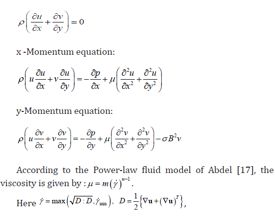
blood consistency coefficient m=0.01625 kg/ms, blood flow behavior index n=0.71775, lower shear rate limit min γ =0.1 1/s, the electrical conductivity σ=1.09 1/Ωs, B is magnetic field intensity acting along x axis, density of blood ρ=1060 kg/m3. The imposed boundary conditions on the blood flow have been written as follows: On the Inlet: velocity u=ui m/s, v=0 m/s, On the Outlet: no viscous stress, pressure p=0Pa, On the other Boundaries: no slip condition u=v =0 m/s.
Solution procedure
For solve the continuity and a momentum equation with associated boundary conditions the Galerkin weighted residual finite element techniques [38,39] have been utilized for numerical simulation. Meant for discretized computational domain the nonuniform six nodes triangular finite elements scheme has been used in the procedure. The fundamental unknowns for the leading partial differential equations are the velocity components (u,v) and the pressure (P). The entire six nodes have been linked with velocities as well as temperature distribution whereas three corner nodes with pressure (P). To carry out the procedure the obtained discretized nonlinear algebraic equations have been modified iteratively by applying boundary conditions. These nonlinear equations have been transferred into linear algebraic equations by means of Newton’s method. Lastly, by using triangular factorization method the obtained linear equations have been solved. The convergence criterion for the solution mechanism has been invoked as ψ n+1 −ψ n ≤10−6 , where n is the number of iteration which is a function of velocity components and pressure.
Mesh generation
To solve BVP in the complex geometry makes the finite element method a prevailing technique occurring in the area of engineering applications. Figure 2 represents the meshing of the present physical model with triangular finite elements.

Figure 2:Finite element mesh of the computational domain.
Grid independent test
To assist the grid independency, a test is conducted for share rates with wide range of meshes through the enclosure. For the present numerical work, five dissimilar non-uniform grid systems with the following number of elements: 5216, 9217, 22692, 54974 and 101272 have been examined within the declaration field as illustrates in Table 1. The shear rate scale for 54974 elements shows a slight dissimilarity with the other obtained result in the present computational domain. Hence, to ensure numerical independency of the grid size the non-uniform grid of 54974 elements has been considered as the best one for the rest of calculations. Since, no further perfection is found for higher values.
Table 1: Grid test at ui = 0.01m/s, B = 2 tesla.

Code validation
For authenticating the accuracy of current numerical process, the obtained results in special case has been compared with that of Akter [40]. Figure 3 displays the validation in terms of the velocity contour. The code validation has been conducted while employing the magnetic field in the horizontal direction and inlet pressure of 10kPa. The present numerical result has good agreement with Akter [40]. These gratifying comparison gives assurance in the numerical results to be accounted later.

Figure 3:Validation of the velocity contour between Akter [40] and that of present research.
Result and Discussion
In this part of the research we depict the blood flow throughout a stenosed human artery for different values of inlet blood velocity from 0.005 to 0.1m/s and magnetic field strength from 0 to 6 tesla. The results have been shown in terms of velocity, plot of velocity magnitude, pressure distribution and viscosity contours. Also, the cross-sectional plots of velocity, pressure and viscosity magnitudes at the stenosed position of artery for the effect of magnetic field have been presented graphically.
Effect of velocity
Figure 4 presents the velocity contour for stenosed artery with B = 2T. First of all, it is seen that because of no slip condition, higher velocity found at the central region of the artery while the lower velocity exist at the wall. The velocity contours are parallel at lowest inflow velocity of blood 0.005m/s. A vortex creates near the upper wall for ui=0.01m/s. This vortex increases in size for further increment of blood velocity. Finally, two big vortexes create near top and bottom surface if the artery for highest velocity 0.1m/s.
The surface plot of the velocity magnitude has been shown in the Figure 5. From the inlet the current flow field gets the shape of the artery which is converges to the stenosed area and diverges to the outlet. Due to increasing inlet blood velocity, the mid part of the artery has higher magnitude and the area of this mid part becomes larger in the surface plot.
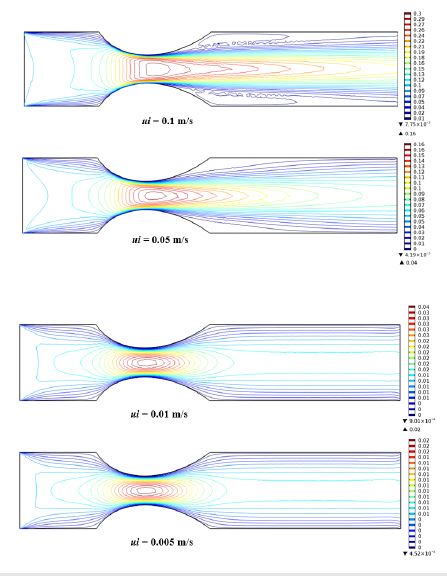
Figure 4:Velocity contour inside artery for various inlet blood velocity at B =2 tesla.
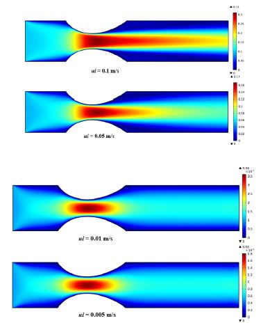
Figure 5:Surface plot of velocity magnitude artery for various inlet blood velocity at B = 2 tesla.
As shown in the Figure 6, parabolic shape pressure lines are found at the inlet port and on the other area they seem almost parallel to the vertical line. The pressure distribution becomes maximum near the inlet and stenosed portion of the artery. For all cases, lower pressures are obtained through the artery whereas after the stenosed area it turns very low which indicates lower velocity at that region.
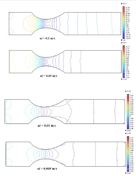
Figure 6:Pressure contour inside artery for various inlet blood velocity at B = 2 tesla.
Figure 7 displays viscosity contour for the considered inlet blood velocity variation. It is found that, viscosity got the analogous pattern as the velocity contour. That is advanced viscosity exists at the middle area of the artery whereas the worse values are found at the wall due to no slip condition. Utmost viscosity exists at the central part of the stenosis due to the contraction of the domain.
Figure 8a & 8b depicts the cross-sectional plot of velocity magnitudes and shear rate versus arc length at the middle of the stenosed part, respectively. The velocity profile is not exactly parabolic, slightly distorted. From this figure it is evident that, velocity magnitude at the cross-sectional line is about 1m/s at inlet velocity 0.005m/s and 2m/s for inlet velocity 0.1m/s due to the stenosis. Shear rates across the stenotic contraction for lower velocity upto 0.01m/s are almost linear pattern but for other inlet velocity it is parabolic shape.
Effect of magnetic field
Figure 9 predicts the velocity contour due to the effect of magnetic field strength (from 0 to 6 tesla) inside the stenosed artery with fixed inlet blood velocity u=0.01m/s. It is seen that, because of wall no slip condition superior velocity subsists at the central area of the artery while the worse velocity is at the wall. Also, at the inlet portion the velocity contours turn into rectangular shape and at the stenosed area it converted to elliptical shape. Maximum velocity contours exist at the middle part of the stenosis. Whereas, the flow field direction at the outlet portion takes the parallel profile as a result from the inlet it converges to the stenosed area and after that it diverges in the direction of the outlet port. No significant change of velocity contours has originated due to the variation of magnetic field strength.
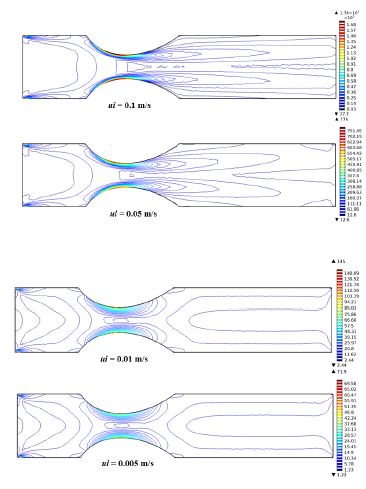
Figure 7:Viscosity contour of artery for various inlet blood velocity at B = 2 tesla.
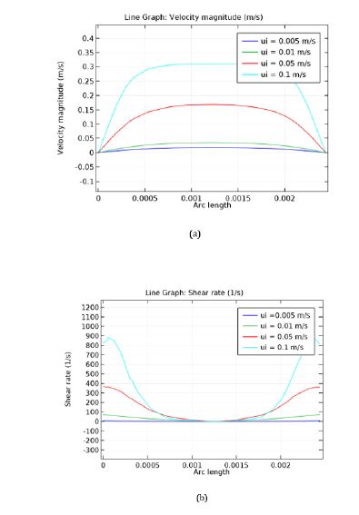
Figure 8:Cross-sectional plot of (a) velocity magnitude and (b) shear rate for inlet velocity variation across the stenotic contraction.
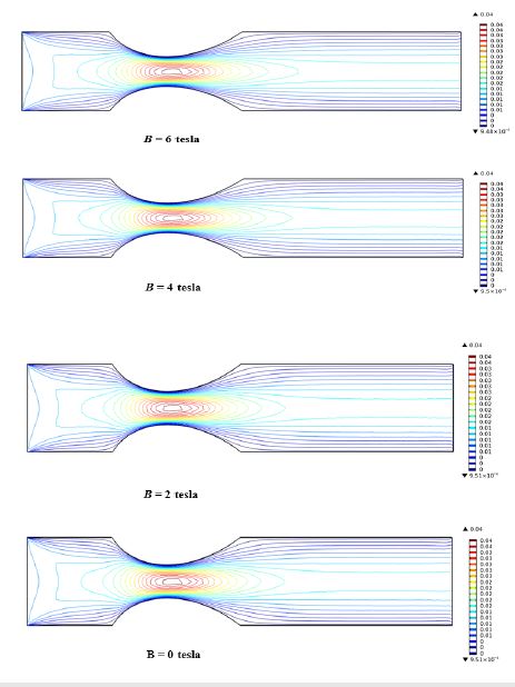
Figure 9:Velocity contour inside artery for various magnetic field at ui = 0.01m/s.
The surface plot of the velocity magnitude has been shown in the Figure 10. Here in all cases, the color changing from blue to red symbolize lower to higher magnitude level. The flow field converges to the stenosed area and diverges from there to outlet. It is also evident from the velocity contours that with escalating magnetic field strength, the mid part of the artery has higher magnitude and the area of this mid part becomes larger in the surface plot.
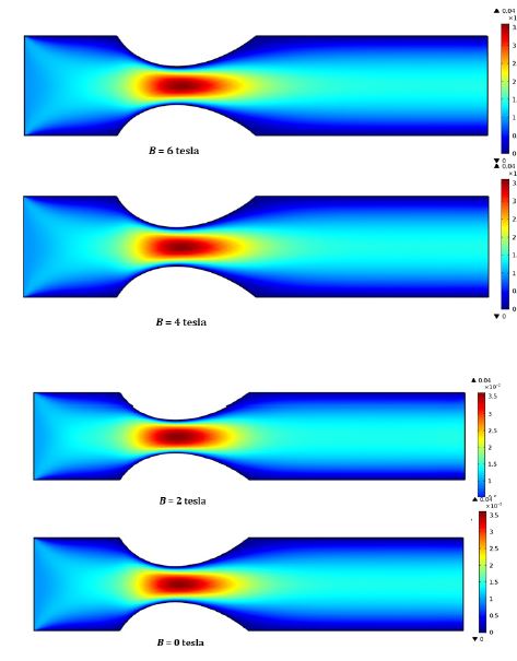
Figure 10:Surface plot of velocity magnitude artery for various magnetic field at ui = 0.01m/s.
Figure 11 shows the pressure distribution due to change of magnetic field strength. The pressure lines at the inlet are almost parallel to the vertical wall and become parabolic at the stenosed portion. The maximum number of pressure line is in the stenosed portion of the artery. After the stenosed portion at the outlet the number of lines become lower and takes the parallel shape to the vertical wall. The lower number of pressure lines indicate the lower pressure. Due to the change of magnetic field strength from 0 to 6 tesla the pressure lines at the inlet portion changes their shapes from straight lines to parabolic lines which indicates higher pressure but after the stenosed portion the lines remain almost similar that indicates at the outlet portion the pressure remains lower with the change of magnetic field strength.
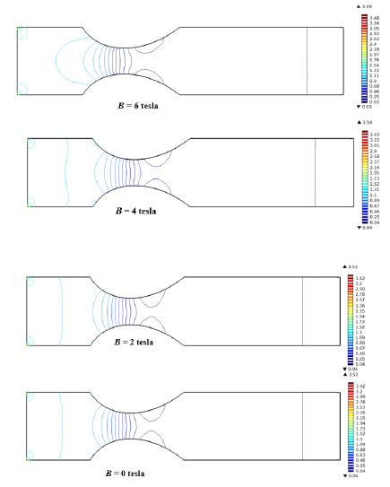
Figure 11:Pressure contour inside artery for various magnetic field at ui = 0.01m/s.
Figure 12 displays the viscosity countour for the considered magnetic field strength variation. It is observed that, at the center part of the stenosis maximum viscosity of blood exists for the contraction of the domain. When the magnetic field strength changes from 0 to 2 tesla the viscosity at the middle of the stenosed portion increases slightly. There is a little bit change noticed in viscosity contour for higher magnetic field strength.
Figure 13a & 13b depicts the cross-sectional plot of velocity magnitude and viscosity versus arc length at the middle of the stenosed part, respectively. The velocity profile is exactly parabolic. From the Figure 13a it is evidently found that, maximum magnitude of velocity at the cross-sectional line is found about 0.038m/s due to the stenosis. There is less difference in cross sectional plot for different magnetic field strength. In the Figure 13b the shear rate across the stenotic contraction is not exactly parabolic it is slightly distorted. For different magnetic field strength, the cross-sectional plot of shear rate is almost similar and there are slight changes which are negligible.
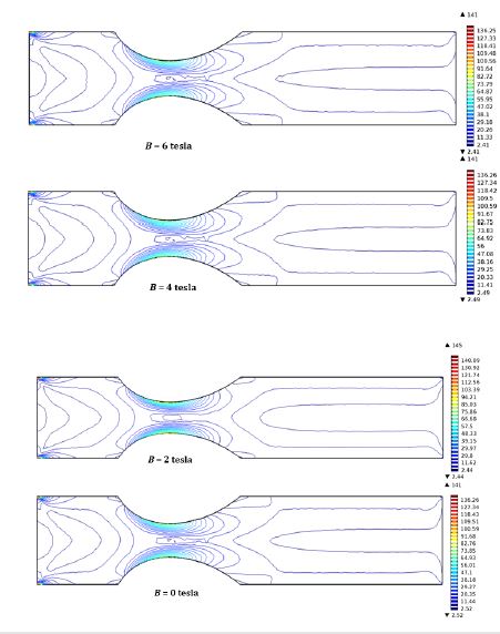
Figure 13:Viscosity contour of artery for various magnetic field at ui = 0.01m/s.

Figure 13:Cross-sectional plot of (a) Velocity magnitude and (b) Shear rate for magnetic field variation across the stenotic contraction.
Conclusion
A numerical study has been conducted of controlling arterial blood flow having a stenosis applying power-law model in the present research. The effect of inlet blood velocity from 0.005 to 0.1m/s on sub-domain velocity, surface, pressure and viscosity contours have been investigated for an arterial stenosis. The imposed magnetic field strength has been considered from 0 to 6 tesla. The current research can be helpful to manage the arterial blood flow at ailing situation. Important conclusions can be enlisted as follows:
A. Higher pressure and velocity are noticed near the stenotic region.
B. The high blood inlet velocity is responsible for lower pressure.
C. Shear rate of blood increases due to increasing inlet velocity.
D. The blood velocity magnitude reduces for the enhanced magnetic field.
E. Increasing magnetic field strength increases the pressure of blood.
F. Shear rate also increases for rising magnetic field strength.
The blood flow information obtained from this research can be helpful in the advancement of diagnosis apparatus for different diseases. The analysis of magnetic field effect will be valuable to manage blood flow at different surgical conditions. The analysis will help in efficient way of such blood flow system of cardiac patient.
References
- Razavi A, Shirani E, Sadeghi MR (2011) Numerical simulation of blood pulsatile flow in a stenosed carotid artery using different rheological models. J of Biomechanics 44(11): 2021-2030.
- Shah SR (2013) An innovative study for non-Newtonian behaviour of blood flow in stenosed artery using Herschel-Bulkley fluid model. Int J of Bio-science and Bio-Technology 5(5): 233-240.
- Akbar NS, Nadeem S (2014) Carreau fluid model for blood flow through a tapered with a stenosis artery. Ain Shams Engineering J 5: 1307-1316.
- Singh S, Shah RR (2010) A numerical model for the effect of stenosis shape on blood flow through an artery using power-law fluid. Advances in Applied Science Research 1(1): 66-73.
- Tanwar VK, Varshney NK, Agarwal R (2016) Effect of body acceleration on pulsatile blood flow through a catheterized artery. Advances in Applied Science Research 7(2): 155-166.
- Singh B, Joshi P, Joshi BK (2010) Blood flow through an artery having radially non-symmetric mild stenosis. Applied Mathematics Science 4: 1065-1072.
- Steinman DA, Vorp DA, Ethier CR (2003) Computational modeling of arterial biomechanics: insights into path ogenesis and treatment of vascular disease. J of Vascular Surgery 37(5): 1118-1128.
- Ismail Z, Abdullah I, Mustapha N, Amin N (2008) The power law model of blood flow through a tapered overlapping stenosed artery. Applied Mathematics Comput 195: 669-680.
- Hasan TABM, Das DK (2008) Numerical simulation of sinusoidal fluctuated pulsatile laminar flow through stenotic artery. J of Applied Fluid Mechanics 1(2): 25-35.
- Akbar NS (2014) Blood flow analysis of Prandtl fluid model in tapered stenosed arteries. Ain Shams Engineering J 5: 1267-1275.
- Uddin MN, Alim MA (2017) Numerical investigation of blood flow through stenotic artery. World J of Engineering Research and Technology 3(6): 93-116.
- Bali R, Awasthi U (2012) A Casson fluid model for multiple stenosed artery in the presence of magnetic field. J of Applied Mathematics 3: 436-441.
- Rahman MM, Hossain MA, Mamun K, Akhter MN (2018) Comparative study of Newtonian and non-Newtonian blood flow through a stenosed carotid artery. AIP Conf Proc 1980, doi: 10.1063/1.5044327.
- Nadeem S, Akbar NS, Hendi AA, Hayat T (2011) Power-law fluid model for blood flow through a tapered artery with a stenosis. Applied Maths and Comp 217: 7108-7116.
- Long Q, Xu XY, Ramnarine KV, Hoskins P (2001) Numerical investigation of physiologically realistic pulsatile flow through arterial stenosis. J of Biomechanics 34(10): 1229-1242.
- Abdel Baieth HE (2008) Physical parameters of blood as a non- Newtonian fluid. Int J of Biomedical Science 4(4): 323-329.
- Peskin CS (1977) Numerical analysis of blood flow in the heart. J Computational Physics 25: 220-252.
- Kumar S, Diwakar C (2013) A mathematical model of power law fluid with an application of blood flow through an artery with stenosis. Advances in Applied Mathematical Biosciences 4(1): 25-36.
- Chandra S, Singh P (2015) Effects of stenosis on power law fluid flow of blood in blood vessels. Journal for Research 1(9): 23-28.
- Imaeda K, Goodman FO (1980) Analysis of nonlinear pulsatile blood flow in arteries. J of Biomechanics 13(12): 1007-1021.
- Srivastava VP (2002) Particular suspension blood flow through stenotic arteries: effect of hematocrit and stenosis shape. Indian J of Pure and Applied Mathematics 33(9): 1353-1360.
- Ponalagusamy R (2007) Blood flow through an artery with mild stenosis: A two layered model, different shapes of stenosis and slip velocity at the wall. J of Applied Sciences 7(7): 1071-1077.
- Srivastava VP, Saxena M (1994) Two-layered model of casson fluid flow through stenotic blood vessels applications to the cardiovascular system. J of Biomechanics 27(7): 921-928.
- Thurstan GB (1972) Viscoelasticity of human blood. Biophysical J 12(9): 1205-1217.
- Sankar DS, Hemalatha K (2006) Pulsatile flow of Herschel-Bulkley fluid through stenosed arteries-A mathematical model. Int J of Non-Linear Mechanics 41(8): 979-990.
- Chakravarty S, Mandal PK (2000) Two-dimensional blood flow through tapered arteries under stenotic conditions. Int J of Non-Linear Mechanics 35(5): 779-793.
- Leuprecht A, Perktold,K (2001) Computer simulation of non-Newtonian effects on blood flows in large arteries. Computer Methods in Biomech & Biomedical Engg 4(2): 149-163.
- Srivastav RK, Agnihotri AK (2014) Non-Newtonian power-law blood fluid flow through bell-shaped stenosis artery. J of Multidisciplinary Scientific Research 2(4): 15-19.
- Shahidian A, Hassemi M, Khorasanizade S, Abdollahzade M, Ahmadi G (2009) Flow analysis of non-Newtonian blood in a magneto hydrodynamic pump. IEEE Transactions on Magnetics 45(6): 2667- 2670.
- Haldar K (1985) Effects of the shape of stenosis on the resistance to blood flow through an artery. Bulletin of Mathematical Biology 47: 545- 550.
- Mathur P, Jain S (2013) Mathematical modelling of non-Newtonian blood flow through artery in the presence of stenosis. Advances in Applied Mathematical Biosciences 4: 1-12.
- BTzirtzilakis E (2005) A mathematical model for blood flow in magnetic field. Physics of Fluids 17: 077-103.
- Mandal PK (2005) An unsteady analysis of non-Newtonian blood flow through tapered arteries with a stenosis. Int J of Non-Linear Mechanics 40(1): 151-164.
- Mantha AR, Benndorf G, Hernandez A, Metcalfe RW (2009) Stability of pulsatile blood flow at the ostium of cerebral aneurysms. J of Biomechanics 42: 1081-1087.
- Mekheimer KhS, Kot MAE (2008) The micropolar fluid model for blood flow through a tapered artery with a stenosis. Acta Mechanica Sinica 24(6): 637-644.
- Shukla JB, Parihar RS, Rao BRP (1980) Effects of stenosis on non- Newtonian flow of the blood in an artery. Bulletin of Mathematical Biology 42: 283-294.
- Hershey D, Byrnes RE, Roam AM (1964) Blood rheology: temperature dependent of the Power-law model. AICH Meeting, Boston, USA
- Taylor C, Hood P (1973) A numerical solution of the Navier-Stokes equations using finite element technique. Computer and Fluids 1: 73-89.
- Dechaumphai P (1999) Finite element method in engineering. (2nd edn), Chulalongkorn University Press, Bangkok, Thailand.
- Akter A, Parvin S (2019) Numerical analysis of a blood flow model for arterial stenosis in presence of external magnetic field. AIP Conference Proceedings 2121(1).
© 2019 R Nasrin. This is an open access article distributed under the terms of the Creative Commons Attribution License , which permits unrestricted use, distribution, and build upon your work non-commercially.
 a Creative Commons Attribution 4.0 International License. Based on a work at www.crimsonpublishers.com.
Best viewed in


.jpg)


 Editorial Board Registrations
 Submit your Article
 Refer a Friend
 Advertise With Us
.jpg)


.jpg)


.bmp)
.jpg)
.png)
.jpg)


.jpg)


.png)

.png)


.png)


