- Submissions

Full Text
Research & Development in Material Science
Aerospace Composite Structure: Routing a Thermoset Composite Fabrication Model by Prepeg Lay-up Medium to Manufacture Sandwich Panels for Aircraft
Ikra Iftekhar Shuvo1*, Md Shadhin2 and Mashiur Rahman2
Graduate Research Student, University of Alberta, Canada
Department of Biosystems Engineering, University of Manitoba, Canada
*Corresponding author: Ikra Iftekhar Shuvo, Graduate student, University of Alberta, Canada
Submission: October 14, 2019;Published: October 21, 2019

ISSN: 2576-8840 Volume12 Issue1
Abstract
Developments of technical textile fibres continued to play an important role in diversifying its application arenas including the inception of advanced composite materials (ACM) using engineered fibres like glass, aramid, and carbon. The aerospace industries have significantly increased the use of ACM due to few factors like higher production rate comparing to unidirectional laminate elements, superior strength to weight ratio over traditional materials (such as metals or ceramics) and enhanced structural stability from interwoven/interlacement of yarns. Automotive and marine industries are also embracing the use of ACM due to its improved tolerance to cut or physical damage. ACM encompasses a wide variety of fabrication model and manual lay-up is the simplest of all. However, there is a knowledge gap among textile academia regarding the hand lay-up model and the science behind it, which is addressed in this case study. To benefit the academia with the knowledge of current aerospace industrial practice, a manual has been prepared in this case study routing the step by step fabrication model with its corresponding schematics and digital imaging during the production protocols of an industrial aircraft composite sandwich panel by using honeycomb aramid core with prepegs (made of technical textile fibres) like graphite and glass fibres.
Keywords: Aircraft panel; Prepeg; Glass fibre; Graphite fibre; Carbon fibre; Aramid; Composite; Honeycomb sandwich; Lay-up; Composite fabrication; Fibre reinforcement; Technical fibre
Introduction
Advanced composite materials (ACM) made with technical textile fibres are of significant interest in aerospace, military weapon, marine, automotive, civil construction and different areas of engineering application due to their distinctive and superior strength to weight ratio over traditional materials (such as metals or ceramics) [1-4]. The aerospace industry is one of the largest consumers of ACM because the industry has reduced the weight of the aircraft panels by more than 40% by replacing aluminum materials with ACM [3]. Besides the lower density (light-weight) of the ACM, the aircraft segment can also be benefitted from the high stiffness, high strength, high axial or longitudinal specific strength [4]. According to the comparative cost principle, the financial advantages possessed by any company engaged in aircraft manufacturing will grow even higher if it can produce a given aircraft panel at lower resource input cost than its competitors, which is possible by replacing aluminum panels with composite panels; because a reduction of 1kg in weight can save fuel cost worth up to $50- $500 USD depending on the types of aircrafts (Figure 1) and global fuel price matrix [3]. T-300 built aircraft payload bay doors can be a real-life example of this comparative cost principle, which is made by carbon fibre-epoxy composite part and demonstrated 400kg of weight saving [4]. Further to the comparative cost and light-weight advantages, Lockheed Martin was also able to simplify their manufacturing assembly by eliminating 95% of the fasteners through the duct because of the use of ACM in the air inlet duct of F35 military fighter jet [5]. A separate study displayed that the total number of components in helicopter manufacturing was dropped by a factor of 7 (from 11,000 to 1500 parts) with a corresponding reduction of 90% in the number of fasteners [4].
Modern day aircraft comprises ACM up to 50% of its total weight, which are applied in different structural and non-structural parts, such as rocket motor castings, aircraft brakes horizontal stabilizer boxes, radomes, spoilers, antenna dishes, wings (prototype ATF), landing gear doors, elevators, and so on [4,6]. Aircraft giants like Airbus, Boeing, Embraer and Lockhead Martin also use fibre-reinforced composites in their aircraft components like winglets (Boeing 737- 300), tail section (Airbus), wing stubs (Embraer ERJ 190) and air inlet duct of F35 military fighter jet (Lockheed Martin) [5,7].

Figure 1:Different types of aircraft (a- passenger Jet, b- private airplane, and c- helicopters). speeds of 10000rpm.
A composite is defined as “a combination of two or more materials that results in better properties than those of the individual components used alone” and typically a continuous or discontinuous phase of a reinforcement (fibre or particulate) and a continuous phase of matrix (polymer resin, metal, ceramic) are the constituents of a composite [8]. There are two types of advanced composite fabrication technologies, such as thermoset composite fabrication (major techniques are - wet lay-up, prepreg lay-up, and low-temperature curing/vacuum bag prepreg layup) and thermoplastic composite fabrication (consolidation, thermoforming, and joining) [8]. Besides the use of synthetic fibres (carbon fibres, glass fibres, aramid fibres) in composite applications, the application of natural fibres in composite fabrication is also predominant due to different mechanical properties of natural fibres [9]. One such example is the lightweight characteristics of textile canola fibres extracted from canola biomass [1]. In a recent research work, it was found that, canola has the lowest fibre density (1.34g/cc) among all major industrial natural fibres (like cotton, jute, flax, and hemp) which is ideal to produce lightweight eco-composites [1,2]. However, there is a knowledge gap among textile academia regarding the industrial hand lay-up methodology for manufacturing protocols and the science behind it, which has been addressed in this case study to benefit the academia with the knowledge of current industrial practice of hand lay-up fabrication method. This current study demonstrates the most simplified and professional manual prepeg lay-up fabrication method to produce ACM for aircraft panels by applying different kinds of prepegs (woven with technical yarns such as carbon/graphite/glass fibres and has been already pre-impregnated with resin matrix) and Nomex® Honeycomb core (manufactured by DuPont from an aerospace-grade heat- and flame- resistant aramid fibre). ACM used in aircraft panels are commonly made of graphite (carbon) fibres, glass fibres, and aramid [3,4,8], which were also applied in this current study. The current study will also brief the science behind the working stages involved in this fabrication model.
MaterialsChamfered Nomex® Honeycomb core material, BMS 8-79 glass fibre (style 220) prepegs and Gr. 190 graphite prepegs were collected from a local aircraft manufacturing company in Winnipeg, Canada for this case study which were stored inside a freezer. It is imperative to monitor the exposure time (“out life” or “mechanical life”) of a prepeg (Appendix-I), which is recorded in the material inspection report. Nomex® Honeycomb aramid materials were also supplied by the same aircraft manufacturing company, which were chamfered to give shape to the core material according to the engineering design. Lay-up mandrel (LM), CPLT (Core & Ply Locating Template), ketone, freekote, vacuum bagging, bleeder, breather, thru-bag vacuum connector, parting film, release ply, and tedlar sheet were used. An air-hose vacuum assembly, automated ply cutting CNC machine, and the autoclave compaction facility (for curing and high pressure) were used for producing this composite sandwich structure applicable for aircraft panel.
Methodology and discussionThe overall engineering design of the composite sandwich panel is represented by schematic diagram illustrated in Figure 2 and the working stages of the prepeg ply collation have been summarized in the working flowchart detailed in Figure 4.
Prior manual prepeg ply collation, the working lay-up mandrel (LM) is cleaned (Figure 5a) with freekote (Figure 7a). For easy removal of the part after manufacturing the composite parts, mold release agent is applied on top of the mold. Frekote is one of the most common mold release agents used in aerospace. These mold release agents are a form of wax that form a film on the outer surface of the part which can be further removed by solvent wiping, sanding, or sandblasting once the manufacturing process is finished. Toluene, xylene, methylene chloride, or acetone are the solvents to be used for removing the mold release agents [11].
Following the cleaning stage, a release ply (peel ply) is placed on the LM and restricted by tool pin (Figure 7b). The release ply is a kind of perforated film that makes the bottom most layer of vacuum bagging material. Release film allows entrapped air, excess resins, and volatiles to escape [11]. The release film helps to prevent sticking of breather or bleeder cloth to the part. Since the release ply is the bottom-most ply of the overall composite panel (Figure 3), it is restricted by the tool pin to prevent the dislocation of the core and prepegs which will be placed on top of the release ply in
The next step is to compact (debulk) the release ply using vacuum assemblies (Figure 7 & 8). A core contact substrate is used to cover the release ply, which is further covered by a vacuum bagging film and attached to the LM by using adhesive sealant to complete the compaction set- up (Figure 6,7,8). The compaction of this stage is done to flatten the release ply without any contour on its surface by removing the entrapped air. In vacuum bagging (or compaction process), bag contents are evacuated, and atmospheric pressure consolidates the composite material [12]. Densification can be achieved by applying differential pressure across the bag walls.
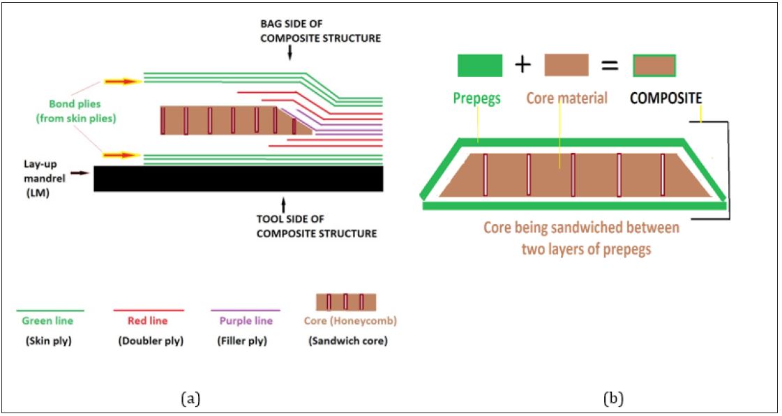
Figure 2:X-sectional diagram (a) of a composite sandwich panel (b) used in aircraft (Appendix-I).
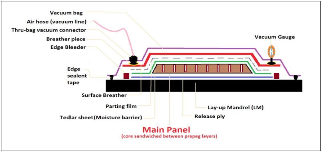
Figure3:DDesigning the fabrication protocols to build an aircraft composite panel.
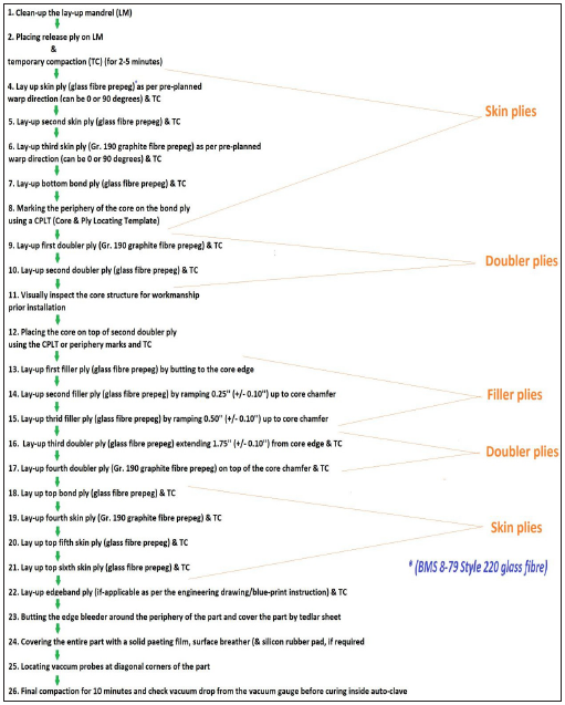
Figure 4:Working flowchart design for different stages engaged in manufacturing aircraft composite panels in the prepeg ply lay-up method (Appendix-I).

Figure 5:Lay-up mandrel (tool side of core) or mold (a) and CPLT (Core & Ply Locating Template) (b) to determine the core placement area and net trim line.
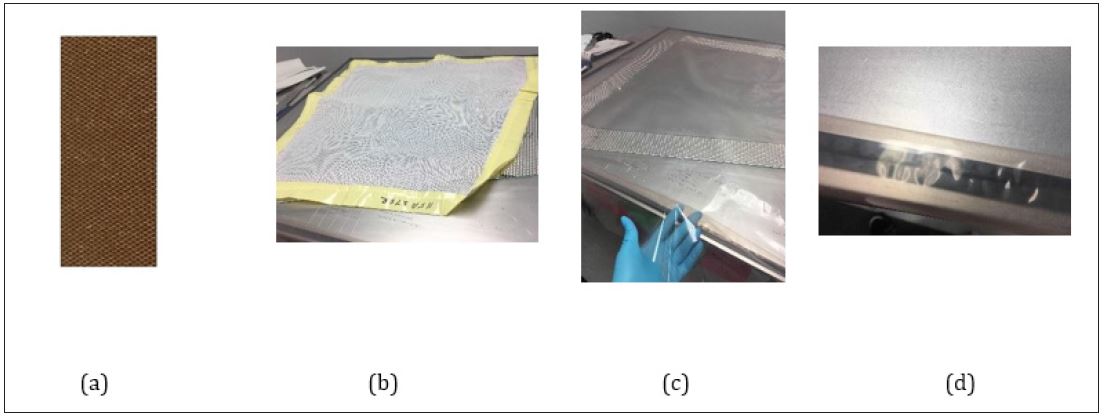
Figure 6:DDu-Pont Nomex® Honeycomb (aramid core) flame resistant sheet (a) and core contact material (b) and non-contact material (c- vacuum bagging film, d- black adhesive sealant lining on the lay-up mandrel or mold to hold the vacuum bagging).

Figure 7Covering the release ply (positioned by tool pin) (b) with vacuum bagging film (c) after applying Freekote on lay-up mandrel.
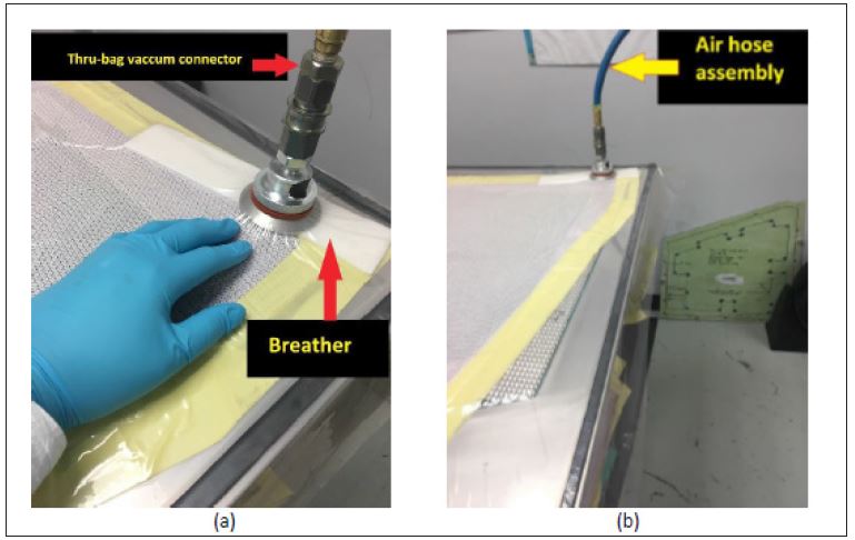
Figure 8:Compacting the release ply by connecting thru-bag vacuum connecter (a) with vacuum air hose assemblies (b).
Following the compaction step, prepeg lay-up is executed precisely as per the engineering design. The quality of workmanship plays the vital role in this stage of laying up the prepegs. These prepegs can be made of glass fibre, carbon/graphite fibres or different high performance fibres which are woven according to the requirement of the aerospace industries. For ease of industrial education, these prepegs are classified with different terms, such as skin ply, bond ply (skin plies in direct touch with the core), doubler ply, filler ply, edgeband ply and so on (Appendix-I). After unloading the prepeg fabric rolls from freezer, the rolls are first installed into an automated CNC ply cutting machine which is preprogrammed to cut the prepegs according to the engineering need of the composite panel design.
After completing the compaction of release ply, the skin plies are laid on the release ply situated on the LM (Figure 2 & 9) as per the design protocol of engineering drawing provided. It is very important to compact the plies after each subsequent layup detailed in the working flowchart (Figure 4). A Core and Ply Locating Template (CPLT) (Figure 5b) is laid on the bottom bond ply to mark the periphery (Figure 10) of the honeycomb core for purpose of placing the core onto the bond ply within the periphery line (Figure 11 & 6a).
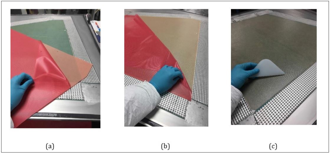
Figure 9:Laying-up glass fibre prepeg (1st skin ply) (a) on the release ply (b) followed by laying-up carbon fibre prepeg (2nd skin ply) on 1st skin ply (c).
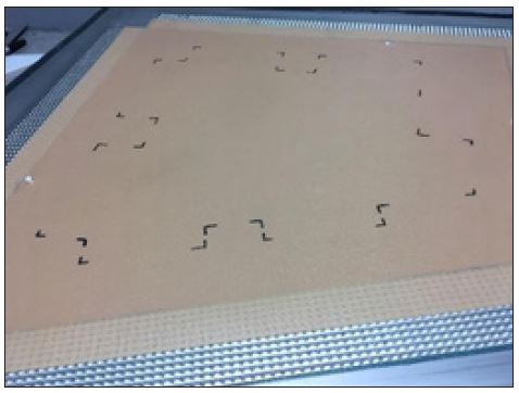
Figure 10:Marking the periphery of the core using CPLT on the bond ply (skin ply touching the honeycomb core).
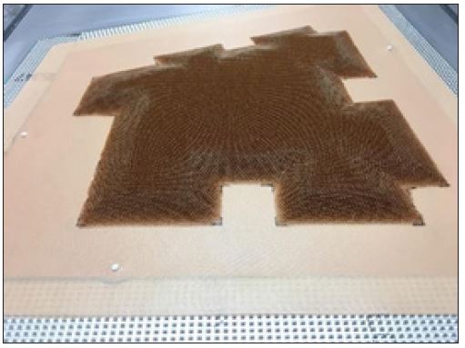
Figure 11:Placing the honeycomb core on the doubler and bond plies
fibre reinforcements. After finishing the lay-up of all the prepegs, a temporary compaction is done on the working panel (Figure 4). To cure the structure inside an autoclave (high temperature treatment), additional preparations are made which are illustrated in Figure 3, 14-17.
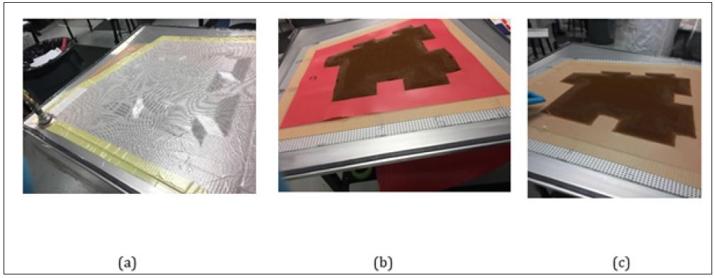
Figure 12:PPutting glass fibre filler plies (b, c) after compacting the honeycomb core (a).

Figure 13:Placing the top bond ply (a) and the rest of the skin plies (b, c) on the honeycomb core once the filler and doubler plies have been positioned as per the lay-up plan.
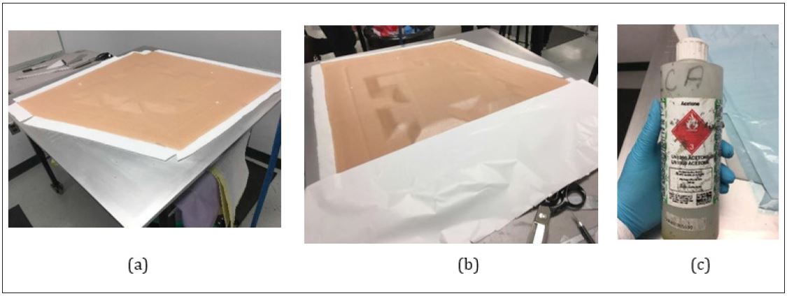
Figure 14:Placing bleeder (a) at the periphery and white tedler sheet (b) on top of the top skin ply once the black adhesive material has been removed and the area has been cleaned by ketone (c).
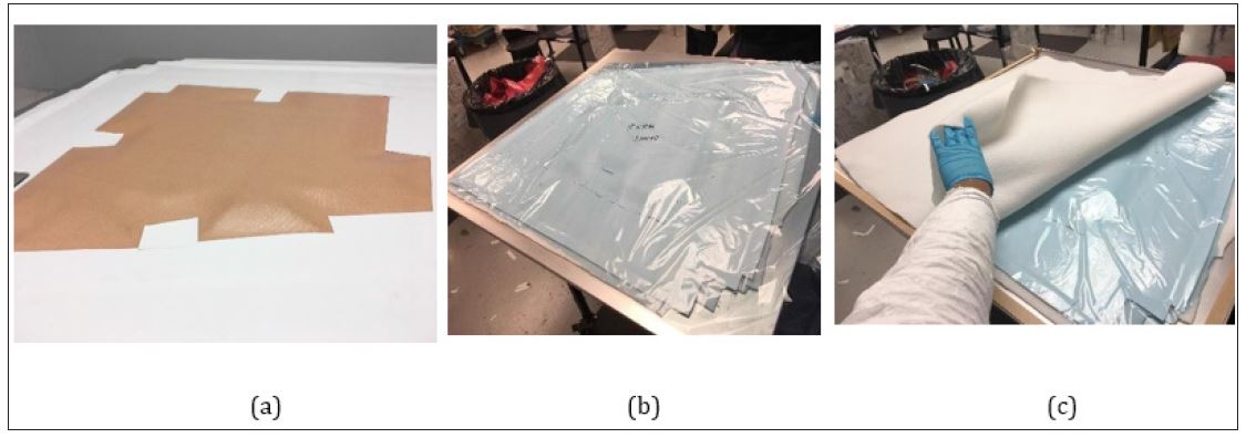
Figure 15:Covering the entire working panel with blue parting film (b) followed by a white breather fabric (c) after laying-up the tedler sheet (a).
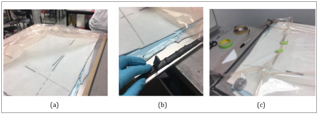
Figure 16:Marking the uneven areas on breather (a) before covering the entire working panel with vacuum bagging (c) and attaching on the lay-up mandrel by an edge sealant tape (black adhesive) (b).
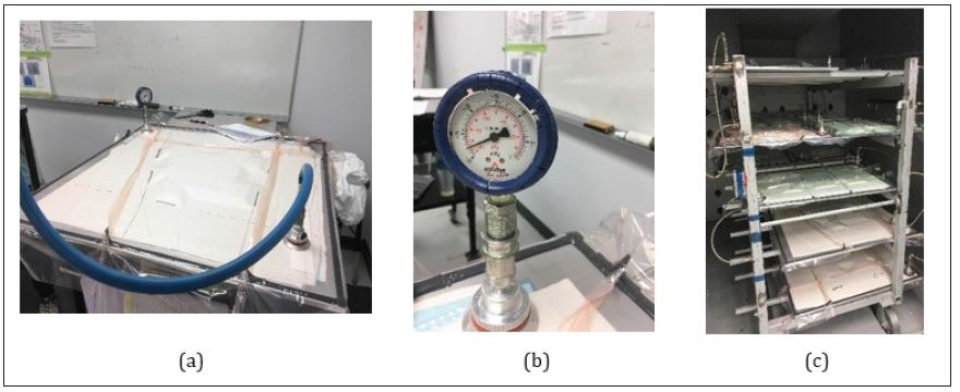
Figure 17:Measuring the pressure drop (Hg) by a vacuum gauge (b) after completing the compaction (a) before placing the working panel inside a high-temperature autoclave (c) for curing and pressure application.
After laying-up all the prepegs, the periphery of the working panel is butted with bleeder fabric mat (Appendix-I) followed by covering the entire working panel with tedlar sheet (a moisture barrier sheet), a parting film, and a breather fabric (Appendix-I) on top of each other (Figure 14, 15 & 16). Moisture content plays an important role in the mechanical performance of thermoset composites. Exposure to moisture results in significant drops in tensile and flexural properties due to the degradation of the fibrematrix interface [11]. Hence, it is essential to use a tedlar sheet as a moisture barrier in composite fabrication.
The pressure drop (Hg) is measured using a vacuum gauge following another round of temporary compaction and before putting the working panel inside an autoclave (Figure 17c). A standard of vacuum drop is maintained in the aerospace industries. If, under full vacuum (22 inches of Hg minimum) the maximum drop in vacuum is 5 inches within 5 minutes, then the final compaction (outside autoclave compaction stage) is considered approved. Otherwise, the sealed edges (by adhesives) of the vacuum bag on the LM is closely observed and fixed to meet the pressure drop standard. However, for assemblies containing core thickness 1’’ or greater, the vacuum drop should be limited to 8-10 inches Hg to prevent core crush or core movement. A schematic diagram of the final vacuum bagging is displayed in Figure 3.
Curing and compaction pressure inside the autoclave is the final step that take place during the fabrication of this thermoset composite sandwich panel for aircraft. Multiple working panel can be inserted inside an autoclave (Figure 17c) depending on its capacity.
Compaction pressure is applied in autoclave process by vacuum bagging and by pressurizing the chamber with air [11]. Apparently, the flexural strength and modulus of manufactured composites is dependent on density or volume fraction of reinforcement and void content. The density or volume fraction of reinforcement and void content can be altered by compaction pressured applied in autoclave thus affecting the flexural properties of composites. An increase in the compaction pressure in autoclave causes the decrease in void content with corresponding increase in flexural strength and modulus which is shown in Figure 19; [13]. Compressive pressure also affects the density or volume fraction of reinforcement. An increase in the pressure results in increase in the density of the material which corresponds to an increase in the fibre volumefraction illustrated in Figure 20. The increase in density or volume fraction was obtained both as a result of the decrease in the void content and the pressure squeezing more resin from out of the layup [12].
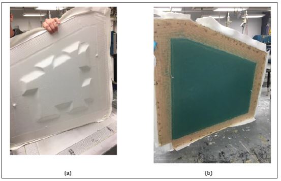
Figure 18:Bag side (a) and tool side (b) of the composite panel after separating from the lay- up mandrel or mold.
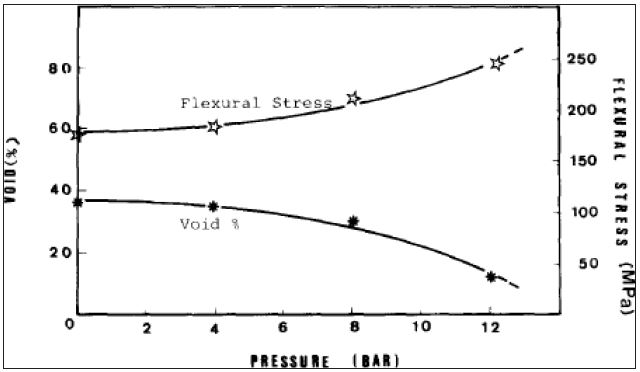
Figure 19:Effect of autoclave pressure on void content % and flexural stress of composites [10].
The process of polymerizing thermosets is known as curing, which takes place inside the autoclave. In other words, curing is a process of polymerization and cross-linking of a monomer or a hardener mixture. Curing process involves mixing of monomers with cross-linking monomer and an initiator or catalyst to result in cross-linked polymer. The properties of the processed laminate depend on the degree of cure. Time, temperature, and pressure are the three important factors during curing process. An efficient curing cycle should be designed for the minimization of curing time, proper temperature management of the thermoset composite part, and proper management of the viscosity and gel point of the resin. To design a cure cycle, the cure kinetics of a thermoset composite part need to be analysed. Cure cycle can be designed in one step or two steps. In case of autoclave processing, additional two step temperature cycle is used for low flow system to design a curing cycle. In composite engineering, the initial temperature cycle is designated by Thold and the final temperature cycle is designated by Tcure. The relevant time at hold (thold) and cure (tcure) cycle is essential to design the curing cycle. To select the appropriate curing temperature, it is important to know about the degradation temperature as well. Therefore the primary parameters to design a two-step isothermal cure cycle in case of an autoclave processing are: (i) temperature at hold step, Thold; (ii) time needed to accomplish hold step, thold; (iii)Temperature at cure step, Tcure; (iv) Time needed to accomplish the cure step, tcure; (V) viscosity of resin, μ; (vi) Degree or extent of curing, α; (vii) Degradation temperature, Td; and (viii) Pressure (autoclave pressure and vacuum pressure). Technical knowledge on ramp rate is significant and can be considered as secondary criterion for designing the cure cycle. Ramp rate influences the viscosity and gel point of the resin. Different ramp rates are used to design a cure cycle. A typical two step cure cycle during autoclave processing is illustrated in Figure 21.
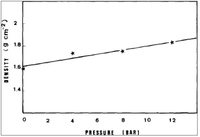
Figure 20:Effect of autoclave pressure on the density of the reinforcements inside a composite structure [10].
Once the curing process is completed (curing can extend upto 24 hour and varies according to end-application and types of prepegs), the working panel is ready (Figure 18) to be used and assembled with other finished panels according to the aircraft blueprint design.
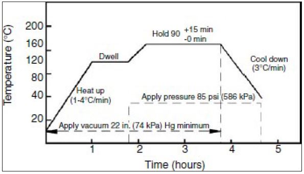
Figure 21:Typical cure cycle during autoclave processing [10].
Conclusion
Advanced composite materials (ACM) reinforced with technical fibres are the fastest growing sector of technical textiles and have successfully attracted the attention of aerospace, automotive, and marine industry leaders like BMW, Marcedes, Boeing, Lockheed Martin, Airbus and so on. A fundamental understanding of the prepeg lay-up fabrication model and the science behind it will be highly effective for textile academia to prepare and train themselves for effective integration with the industries engaged in ACM.
Acknowledgement
The authors are thankful to University of Manitoba (Canada).
ACase Study Focus Group
The study is entirely focused to benefit the students involved in textile science and engineering education, who strive to work on the fastest growing sector of textile industries i.e., technical textile (reinforced composites), but fail to get access to proper study materials. Students with textile engineering and science background are mostly exposed to the traditional textile and apparel studies with a very minimal exposure to technical textile industries, which was felt and observed by the authors. To bridge this knowledge gap and academic need, the authors prepared this case study material based on the current manufacturing practice of aerospace industries.
Appendix- I
1. MECHANICAL LIFE- Mechanical life of a prepeg is from the time out of freezer (in hours) upto the initiation of the cure cycle.
2. BAGSIDE- Side of the assembly part that is cured against the vacuum bag.
3. TOOLSIDE- Side of the assembly part that is cured against the lay-up mandrel (LM).
4. SKIN PLY- Skin plies are plies that covers the core bay and/or encompasses the entire area of a bond assembly.
5. BOND PLY- Bond plies are skin plies that are placed in contact with the honeycomb core.
6. DOUBLER PLY- Doubler plies are plies that are used as structural reinforcements in localized areas of the part.
7. FILLER PLY- Filler plies are plies that are used to maintain laminate/core thickness.
8. CONTACT MATERIAL- Contact materials are defined by all bagging material that contacts the part inside the net trim line prior to cure.
9. NON-CONTACT MATERIAL- Non-contact materials are defined as the materials that cannot touch the prepeg materials inside the net trim line prior to cure.
10. DELIVERABLE MATERIAL- Deliverable materials are materials included in the final part/panel delivered to the assembly department.
11. NET TRIM LINE- Net trim line is the periphery (inside the Core & Ply Locating Template) of the deliverable part per engineering drawing.
12. BLEEDER- Bleeder prevents the resin from escaping from the edges) [9].
13. BREATHER- Breather is a porous material that serves as a continuous vacuum path over a part and allows air and volatiles to evacuate out and is not allowed to directly contact the deliverable material (composite panel) [9].
References
- Shuvo II (2018) A smart textile fibre from biomass of brassica napus L and the impact of cultivar on fibre quality. University of Manitoba, Winnipeg, Canada.
- Shuvo II, Rahman M, Vahora T, Morrison J, Ducharme S, et al. (2019) Producing light weight bast fibres from canola biomass for technical textiles. Textile Research Journal, California, USA.
- Karaduman NS, Karaduman Y, Ozdemir H, Ozdemir G (2017) Textile reinforced structural composites for advanced applications. In: Bipin K, Suman T (Eds.), Textiles for Advanced Applications.
- Pilato LA, Michno MJ (1994) Advanced Composite materials. P. 208.
- Baker A, Dutton S, Kelly D (2004) Composite materials for aircraft structures. American Institute of Aeronautics and Astronautics, Virginia, USA, pp. 599.
- Mullen CK, Roy PJ (1972) Fabrication and properties description of Avco 3D carbon-carbon cylindrical composites. In: National SAMPE Symposium, Los Angeles, USA. <
- Liu Y, Araujo M, Hu H (2016) Advanced fibrous architectures for composites in aerospace engineering. In: Rana S, Fangueiro R, (Eds.), Advanced composite materials for aerospace engineering: Processing, properties and applications, England, pp. 17-58.
- Horrocks AR, Anand SC (2000) Handbook of technical textiles. Woodhead Publishing Limited, England.
- Campbell FC (2010) Structural composite materials. Materials Park, Ohio, USA.
- Mazumdar S (2001) Composites manufacturing: Materials, product, and process engineering. CRC press, USA.
- Dhakal HN, Zhang ZY, Richardson MOW (2007) Effect of water absorption on the mechanical properties of hemp fibre reinforced unsaturated polyester composites. Composites Science and Technology 67(7-8): 1674-1683.
- Boey FYC, Lye SW (1990) Effects of vacuum and pressure in an autoclave curing process for a thermosetting fibre-reinforced composite. Journal of Materials Processing Technology 23(2): 121-131.
- Sergio O, Sergio A, Oller A, Liz GN, Xavier M (2018) Comprehensive Energy Systems. 2: 235-265.
© 2019 Ikra Iftekhar Shuvo. This is an open access article distributed under the terms of the Creative Commons Attribution License , which permits unrestricted use, distribution, and build upon your work non-commercially.
 a Creative Commons Attribution 4.0 International License. Based on a work at www.crimsonpublishers.com.
Best viewed in


.jpg)


 Editorial Board Registrations
 Submit your Article
 Refer a Friend
 Advertise With Us
.jpg)


.jpg)


.bmp)
.jpg)
.png)
.jpg)


.jpg)


.png)

.png)


.png)


