- Submissions

Full Text
Research & Development in Material Science
Experimental and Numerical Approach to Investigate Damage Tolerance in FRP Composites Subjected to Transverse Low-Velocity Impact
Prashant Rawat1,3*, Nand Kishore Singh2, Kalyan Kumar Singh3 and Ashish Kumar4
1 School of Mechanical Engineering, Lingaya’s University, India
2 Department of Mechanical Engineering, Dayananda Sagar University, India
3 Department of Mechanical Engineering, Indian Institute of Technology (ISM), Dhanbad, India
4 Department of Mechanical Engineering, Dehradun Institute of Technology, Dehradun
*Corresponding author: Prashant Rawat, School of Mechanical Engineering, Lingaya’s University, Faridabad, Haryana-121002, India
Submission: August 02, 2018; Published: October 17, 2018

ISSN: 2576-8840 Volume8 Issue2
Abstract
This paper bridges the gap between experimental work and numerical simulation to investigate the damage caused in glass/epoxy laminate. A major drawback of low and/or high-velocity impact on polymer composite is online monitoring of induced stress, stress pattern and cross-section study of damage formation. Drop weight impact is done to investigate energy absorption and damage caused in glass woven composite laminates. Validation, as well as the elimination of experimental limitations, is done using 3D commercially available finite element software LS-DYNA. Eight layered symmetrical laminate of glass fiber reinforced polymer (GFRP) composite was fabricated using hand layup technique assisted by vacuum bagging method. Lowvelocity impact (LVI) testing is done at three energy levels 50J, 70J and 90J. Results of the study justified a good agreement between experimental work and numerical modeling. Furthermore, the present investigation concluded that it is nearly imperfect if only experiment-based study or FEM analysis is performed for LV indentation. Hence, to attain throughout evaluation of damage resistance it is necessary to consider both methods i.e. experimental approach and numerical analysis simultaneously.
Keywords: FRPs; Symmetrical laminates; LVI; Damage tolerance; LS-DYNA
Introduction
Fiber reinforced polymers (FRPs) are the most popular material for advanced structural applications in several industries. The reason for this wide-ranging application fields is unique properties offered by FRPs like high strength and stiffness, high energy absorbing capacity, low mass to strength ratio. In daily life application, composite parts are subjected to several loading conditions in which low-velocity impact (LVI) is one of the loading conditions as well as a real life problem [1,2]. This low-velocity indentation can cause matrix failure, delamination, and fiber breakage of the composite component. Failure modes in lowvelocity impact are delamination, fiber shear failure, tensile fracture of the matrix, localized compressive failure [3]. Grave concern of LVI is barely visible damage (BVD) which exists in form of matrix cracking or delamination. These failures are directly dependent on composite component i.e. fiber type, matrix, fiber orientation (layup) and thickness of laminate, loading conditions of impactor and impactor shape. Mass and velocity of impact Meanwhile high velocity with a low mass impactor and/or low velocity with high mass impactor causes different delamination area also different fiber layup shows the difference in delamination pattern. Thus it is strongly preferred to consider energy criteria for impact damage analysis [4].
Symmetrical FRP laminate design with eight layers have higher damage resistance as compared to asymmetrical laminate design [5]. Moreover impact induced damage area in symmetrical layup design with a pre-crack was found less as compared to an asymmetrical laminate design using 12J impact energy [6]. These investigations signify importance of symmetrical design of laminates in prospective of damage tolerance. Ghasemnejad et al. [7] performed Charpy impact test considering ply delamination as the prime mode of failure and validated results using LS-DYNA conclusions of the study justified that hybrid laminates have the capability to absorb more energy in low velocity impact. Borg et al. [8] developed a delamination model for transverse impact simulations, and this model justified that prepared model was capable of determining initiation of delamination as well as the growth of transverse impact simulations. Jiang et al. [9] modeled a dynamic problem in LS-DYNA for analysis of local displacement in honeycomb core in low-velocity impact. Experimental and numerical analysis of impact response using LS-DYNA justified about the correlation in results [10] while a reasonable suggestion was made regarding better failure model to get more accuracy. Lowvelocity impact analysis using LS-DYNA for glass/epoxy composite concluded [11] about the accuracy of numerical modeling and delamination at interfaces. Several researchers focused on [10- 13] on different objectives in experimental investigation and/or numerical models. Their objective is to focus on a problem related to particular method. Furthermore, numerical simulations have been used for validation purpose only [5]. Therefore, previous investigations failed to justify limitations of the each methods (testing and FEA) by using a parallel approach.
This paper reports about low velocity impact of symmetrical designed glass/epoxy composite plate which is exposed to three energy levels of 50J, 70J and 90J. The validation of the impact testing was done using LS-DYNA and limitations of experimental technique have been eliminated as well. For example, timedependent initiation and propagation of damage which leads to delamination together with stress and strain during impact testing is a tricky affair and/or limitation of the experiment testing. This limitation could be eliminated by numerical simulation using FEM software. In this way, this research proposes a novel method for the complete study of damage tolerance of GFRP laminate by combining experimental and numerical simulation.
Fabrication of composite laminate
Previous work [5] justified about the prominence of symmetrical laminate design for damage tolerance. Thus, sample of glass/ epoxy composite was prepared in the same fashion i.e. eight layered symmetrical design with [(00,900)/(+450,-450)/(+450,- 450)/(00,900)]S layup using bidirectional glass fiber woven. In order to make resin solution L-12 based epoxy (bisphenol-A) and N,N’-Bis(2-aminoethyl) ethane-1,2-diamine, a room temperature hardener K-6 were mixed in 10:1 ratio (both were purchased from Atul Ltd., Gujrat, India). Mixing of epoxy and hardener was done for 20 minutes using bath ultrasonication technique.
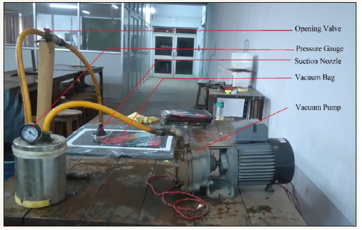
The glass woven is then cut into 28 X 28cm2 area in two orientations (00/900) and (+450/-450). Resin solution is applied on glass woven by a soft brush keeping it on a flat glass surface. As per the laminate design eight layers of glass woven were stacked, to remove extra resin an iron roller was rolled properly after placement of each layer. This wet laminate of 28 X 28cm2 size was finally placed inside prepared vacuum bag, 0.9atm. pressure is achieved using a vacuum pump (Figure 1). This constant pressure is applied for 30 minutes in order to squeeze maximum resins form the wet laminate. For curing of the composite laminate 30Kg. weights were placed over laminate for another 24 hours in room atmospheric conditions.
Figure 1:Vacuum bagging setup
Experimental process and testing
Figure 2:Impact testing setup.
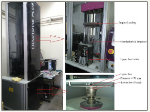
Glass fiber reinforced polymer laminates were cut in 100mmX- 100mmX4mm dimensional size and drop weight impact testing is performed according to ASTM D7136 standards. Experimental testing was conducted on CEAST 9350 (Figure 2) with a hemispherical headed cylindrical steel impactor of 20Kg. and 12.7mm diameter. Impact energy for experimental testing was selected 50, 70 and 90J for composite laminates. Square shaped specimen clamping is done using fixture provided i.e. composite plate was placed over lower fixed jaw and clamping is done using upper movable jaw both jaws were hollow at the centers with 76mm diameter from the centre as shown in Figure 2. Impact testing is done in room atmospheric conditions.
Numerical simulation
Modeling and Meshing of composite laminates, steel impactor is done in HyperMesh v9.0. The elements of the composite and impactor were modeled by solid element and element size was 1mm2. Numerical simulation of drop weight indentation is done in 3-dimentional commercially available software LS-DYNA 4.2 (beta) version.
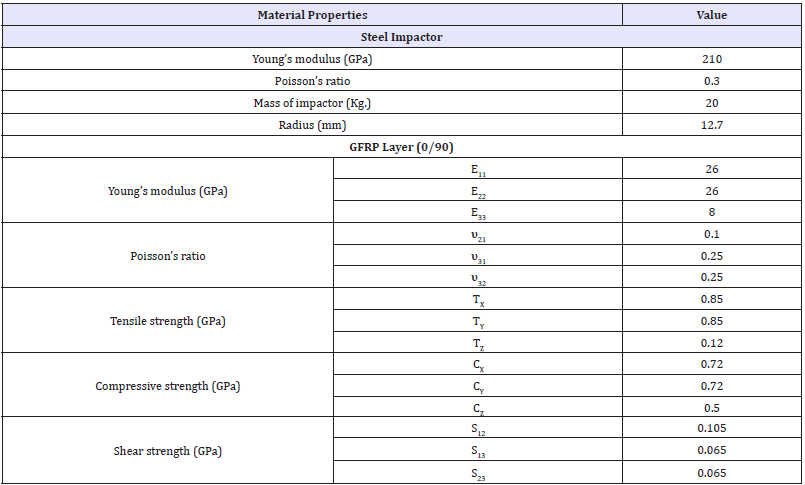
MAT-20/RIGID material card is used to define properties of steel indenter. The rigid material card does not deform during impact and behaves like a rigid component during indentation with FRPs. MAT-59/SOLID_COMPOSITE_FAILURE_SOLID_MODEL material card which is capable of defining orthotropic materials was used to identify the properties of proposed GFRP composite (Figure 3). MAT-59 also allows providing material axes option by defining AOPT and BETA values. In this simulation, BETA=3 and AOPT=45 used to rotate lamina by 450 angles. Table 1 represents the material properties for impactor and laminate used in numerical simulation. AUTOMATIC_SURFACE_TO_SURFACE material card was opted to define contact between impactor and each lamina while TIED_SURFACE_TO_SURFACE used for defining contact between two laminae. BOUNDARY_SPC selected for defining the boundary conditions as per actual experiment conditions, laminate boundaries were constrained in translation and rotational directions of 76mm radius outside the laminate (Figure 3). The impact energy of 50J, 70J and 90J were provided to the impactor by using initial velocity option available in simulation software. The simulation time for the experiment was 5ms as per the unit system selected in LS_DYNA.
Figure 3:GFRP laminate and boundary conditions.

Table 1:
Results and Discussion
Energy-time relations
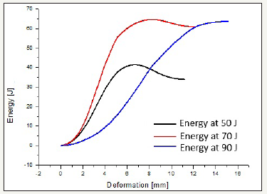
In the case of impact problem a threshold impact energy is needed to penetrate or completely damage fiber reinforced target material [14]. During impact, energy absorption mechanisms are a shear plug (shear-out) mechanism, delamination and elastic flexural. Damage mechanism also affected by the velocity of an impact as in the case of high-velocity impact contact time of impactor and laminate is too short while in the case of low-velocity impact contact duration is long comparatively [15]. Impact energy absorbed by FRP laminate primarily stays in for form of strain energy while after short time interval dissipated through several failure modes i.e. matrix cracking, delamination finally fiber breakage. In this problem considered contact time was 5ms for the experiment as well as in numerical analysis. Figure 4 shows energy-deformation curves at three energy levels 50J, 70J and 90J. Maximum energy absorbed at 50J, 70J and 90J energy were 42.7J, 65.3J and 65.4J respectively. Maximum energy absorption for 50J caused rebounding of the indenter and damage caused was in form of matrix cracking and delamination. No fiber pull-out was observed whereas fiber cracking was visible at the bottom side of GFRP plate. There is no enhancement in energy absorption capacity at 70J and 90J indicates ultimate energy absorption ability of the composite laminate. At both energy levels all three mechanisms like matrix failure, delamination and fiber failure were observed and discussed in other sections.
Figure 4:Energy-time curves.
Force-time curves
Figure 5:Force-time curves.
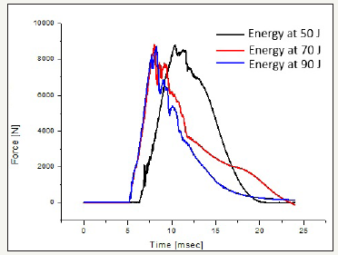
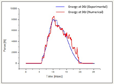
Force-time behavior of low-velocity impact defines maximum force absorbed during impact while maximum force or peak force is a value of maximum load bearing capacity of the laminate. Figure 5 represents the force-time behavior at 50J, 70J and 90J energy levels. Peak force and curve pattern at 70J and 90J energy level is almost same. At energy level of 50J peak load achievement was delayed (shown on x-axes) due to minimum velocity relatively and thus for this case maximum contact time of indenter and laminate was seen. Load curves also highlighted damage caused in laminate as first crack generation which is caused in matrix of the composite plate in all three curves (at different energies) first crack is visible and it is instantaneous process. After generation of the first crack (generates in matrix) laminate takes load and reaches up to a peak load. At this stage sharp glance at the top for 70J and 90J represented complete penetration of indenter. After this stage laminate layers takes load can be observed in form of plateau. In general, it can be concluded as after reaching maximum load layer by layer failure of the composite plate starts and this region continues till impactor completely penetrates the laminate (Figure 5). In order to investigate the results of numerical simulation comparison of load curves is done for 90J impact energy. Figure 6 validates the force-time behavior at an impact energy of 90J; a good agreement justifies the significance of FEM simulation.
Figure 6:Compare of experimental and numerical results.
Pyramidal damage
Figure 7:Calculation of pyramidal height rectangular damage.
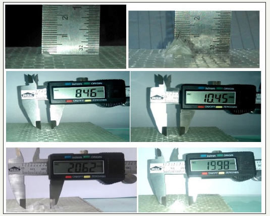
Comparison of damage pattern after low-velocity impact on front and faces were studied for proposed energy levels. Visible pyramidal damage was measured in both warp and fill direction and visual damage was compared with numerical results. At top face of the GFRP laminate, the point where impactor contacts with composite plate compression mechanism dominate while on the other side i.e. at bottom face fiber pull-out took place. Cross-section investigation was done by finite element method represented these both mechanism evidently (Figure 7 & 8). Pyramidal damage calculation method is shown in Figure 7 & 8 compares experimental and numerical damage patterns.
Figure 8:Damage caused in numerical and experimental analysis.
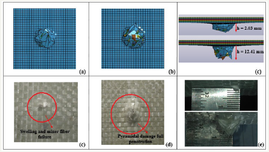
During LVI composite laminate goes under tension and compression in the direction of the fiber, and in-plane shear in transverses direction. In this work, it was observed that impactinduced damage pattern looked like reverse pine tree pattern [16] while due to long impact time laminate respond was quasistatic respond [17]. Table 2 represents the visual damage caused i.e. rectangular damage in weft and warp direction, height of the pyramid. This visual damage area highlights that with the increase in indent energy visual damage is increased.
Table 2:Pyramidal damage area.

Limitations of the experimental study
As discussed in introduction section, experimental testing does not provide complete analysis of the drop weight indentation. Limitations related to layer by layer stress distribution, stress pattern in laminate and penetration pattern are major shortcomings of experimental testing. Furthermore, these limitations are related to online monitoring and certainly resolved with finite element analysis, once numerical technique is validated according to experimental results. Therefore, present study attempts to propose a combined approach for generalized investigation of low velocity impact problem over FRP composite laminate.
Stress pattern
Figure 9:Maximum stress induced in impact test.

Analysis of stress induced during impact testing is a one of the major limitation in experimental process. While, this restriction can be easily overcome in numerical simulation. Figure 9 shows maximum stress induced in proposed LVI over GFRP. Table 2 provides stress pattern generated in layer by layer in a composite plate in all three directions (x, y and z axes) at 90J energy of impact. This table also justifies the importance of orientation of ply as when ply orientation changes the pattern of stress also induces changes according to the fiber direction. Overall stress generated in laminate confirmed that stress generation depends on the indentation energy as stress region for 50J impact energy is found to be minimum whereas stress affected zone increased with the increase in impact energy i.e. 70J and 90J as shown in Figure 9.
Cross-sectional penetration
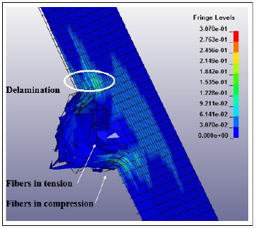
Finite element simulation (LS-DYNA) allows to study and compare penetration pattern as well as damage caused in timesteps. Figure 7 compared cross-sectional penetration caused at three energy levels, 50J, 70J and 90J respectively. Figure 10 shows the cause of fiber cracking only at 50J energy as impactor did not penetrate completely hence only fiber crack was observed on the bottom side. Maximum damage caused at this energy was visible in only one component i.e. matrix zone and it was in the form of matrix cracking and delamination. While at 70J and 90J impactor penetrated as well as caused pyramidal damage can be seen in Figure 10. Cross-sectional analysis using LS-DYNA also provide laminate damage morphology (Figure 11) and different loading conditions as well after complete penetration. All damage mechanisms related to matrix failure and fiber failure have been represented in Figure 11. This type of analysis is a major limitation of experiment technique i.e. only destructive methods can provide exact loading morphology which are complicated and time taking as well. Therefore, it is necessary to opt both (experiment and FEM) methods for more relevant analysis.
Figure 10:Penetration pattern in time steps.
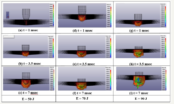
Figure 11:Fiber damage morphology
Scanning acoustic microscopy scanning
SAM is a tool to detect internal damage, KSI scanning acoustic v-400 series microscope was used to calculate maximum internal damage area. Tested samples were scanned layer by layer, sixteen layers were scanned in each specimen of 4mm thickness, and scanning area was 80mm X 80mm. Maximum damage caused by the impactor is then compared to internal damage at three energy levels. It is observed that at 50J impact energy fiber crack and delamination occurred while for an impact energy of 70J and 90J produced complete fiber breakage as well as delamination. Scanning results (Figure 12) confirmed the cross-sectional results of numerical simulations (Figure 8) Table 3. Moreover, stress patterns induced can also be justified by SAM analysis i.e. stress induced is directly proportional to damage caused.
Figure 12:Internal damage caused during LVI (a) 50J, (b) 70J and (c) 90J.
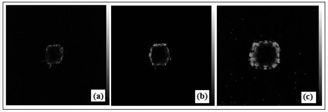
Table 3:Layer by layer stress pattern (in three axes).

Conclusion
Investigation of damage induced in drop weight impact test on glass fiber reinforced polymer laminate is done using a combined approach i.e. experiment and numerical analysis. The symmetrical design glass woven composite with eight plies was tested over three impact velocities 50J, 70J and 90J. Conclusion points of the proposed investigation are:
A. The damage area caused by indenter increases with an increase in incident energy. However, energy absorbed by the laminate did not increase significantly after a certain value.
B. At low indent energy like 50J matrix cracking, delamination and only fiber fracture occur. While over this energy value impactor completely penetrates the specimen causing pyramidal damage i.e. at 70 and 90J energy.
C. Experimental analysis did not provide complete investigation, and these limitations (stress analysis, penetration pattern) can overcome by numerical simulations. It has been justified. This work reports that investigation of LVI is possible using both approaches i.e. experiment and numerical approach.
D. Comparative investigation of damage pattern, pyramidal damage, force-time respond of the experimental and numerical method also justified a good agreement between both works.
Acknowledgement
The authors received no financial funding for this investigation, authorship and publication.
References
- Sandeep A, Kalyan KS, Sarkar PK (2014) Impact damage of fiber reinforced polymer matrix composite- A review. Journal of composite material 48: 317-332.
- Sarasini F, Tirillò J, Ferrante L, Valente M, Valente T, et al. (2014) Drop-weight impact behavior of woven hybrid basalt-carbon/epoxy composites. Composites Part B: Engineering 59: 204-220.
- Reid SR, Zhou Z (2000) Impact behaviour of fibre-reinforced composite materials and structures. Woodhead Publishing Ltd, CRC Press LLC, UK, USA.
- Hufenbach W, Marques FI, Langkamp A, Böhm R, Hornig A (2008) Charpy impact tests on composite structures-An experimental and numerical investigation. Composites Science and Technology 68(12): 2391-2400.
- Kalyan KS, Nand KS, Ratneshwar J (2015) Analysis of Symmetric and asymmetric glass fiber reinforced plastic laminates subjected to low velocity impact. Journal of composite materials 50(14): 1853-1863.
- Kalyan KS, Singh RK, Chandel PS, Kumar P (2008) An Asymmetric FRP laminate with a circular precrack to determine impact induced damage. Polymer Composites 29(12): 1378-1383.
- Ghasemnejad H, Furquan ASM, Mason PJ (2010) Charpy impact damage behaviour of single and multi-delaminated hybrid composite beam structures. Materials & Design 31(8): 3653-3660.
- Rikard B, Larsgunnar N, Kjell S (2004) Simulation of low velocity impact on fiber laminates using a cohesive zone based delamination model. Composites Science and Technology 64(2): 279-288.
- Dazhi J, Dongwei S (2005) Local displacement of core in two-layer sandwich composite structures subjected to low velocity impact. Composite Structures 71(1): 53-60.
- Okenwa IO, Abdul AL (2002) An attempt at predicting failure in a random glass/epoxy composite laminate. Journal of Reinforced Plastics and Composites 21(11): 1003-1012.
- Costantino M, Domenico A, Giancarlo C, Valentina L, Andrea P (2011) Numerical simulation of impact tests on GFRP composite laminates. International Journal of Impact Engineering 38(8-9): 677-685.
- Nand KS, Singh KK (2014) Review on impact analysis of FRP composites validated by LS-DYNA. Polymer Composites 36(10): 1786-1798.
- Prashant R, Kalyan KS (2015) An impact behavior analysis of CNT-based fiber reinforced composites validated by LS-DYNA: A Review. Polymer Composites 38(1): 175-184.
- Abrate, Serge (2011) Impact engineering of composite structures. CISM International Centre for Mechanical Sciences, Italy
- Silberschmidt, Vadim V 2016 Dynamic deformation, damage and fracture in composite materials and structures. Woodhead Publishing, UK.
- Abrate, Serge (1998) Impact on composite structures. The Aeronautical Journal 103(1029).
- Olsson R (2000) Mass criterion for wave controlled impact response of composite plates. Composites Part A: Applied Science and Manufacturing 31(8): 879-887.
© 2018 Prashant Rawat . This is an open access article distributed under the terms of the Creative Commons Attribution License , which permits unrestricted use, distribution, and build upon your work non-commercially.
 a Creative Commons Attribution 4.0 International License. Based on a work at www.crimsonpublishers.com.
Best viewed in


.jpg)


 Editorial Board Registrations
 Submit your Article
 Refer a Friend
 Advertise With Us
.jpg)


.jpg)


.bmp)
.jpg)
.png)
.jpg)


.jpg)


.png)

.png)


.png)


