
- About Us
- Information
-

The Author ensures that the research has been conducted responsibly and ethically with adherence to all relevant regulations. read more..
- For Authors
- For Reviewer
- Manuscript Guidelines
- Membership
- Publication Ethics
-
- Journals
- Reprints
- e-Books
- Videos
- Policies
- Contact Us
 COVID-19
- Submissions


Full Text
Research & Development in Material Science
Abrasive Flow Finishing of Stainless Steel 304 Biomedical Devices
Amir Dehghanghadikolaei1*, Behzad Fotovvati2, Behrouz Mohammadian3 and Navid Namdari3
1 Department of Mechanical, Industrial and Manufacturing Engineering, USA
2 Department of Mechanical Engineering, USA
3 Department of Mechanical, Industrial and Manufacturing Engineering, USA
*Corresponding author: Amir Dehghanghadikolaei, Department of Mechanical, Industrial and Manufacturing Engineering, USA
Submission: August 01, 2018; Published: October 16, 2018

ISSN: 2576-8840 Volume8 Issue2
Abstract
In this experimental study, magnetorheological abrasive flow finishing (MRAFF) process is utilized to observe the effect of different finishing parameters on final surface finish quality. Ability to control over rheological properties of magnetic abrasive medium in MRAFF with exerting an external magnetic field let us reach internal surface finishing process due to its special rheological behavior. A new finishing set designed and manufactured to meet needs for these experiments that consists of a hydraulic-mechanical power unit, abrasive fluid containers, permanent Fe-Nd magnets, workpiece fixtures and a base frame. Finishing fluid in this study contains iron particles as magnetic bonders and SiC particles in different mesh size as abrasive part. In addition, a specific volume percentage of liquid paraffin and glycerin constitute base medium. Experiments were conducted on austenite stainless steel pipes in different magnetic field strength, abrasive particle size and finishing cycle time and were designed in full factorial mode. With increase in magnetic field strength and abrasive particle size, an increase in surface roughness is obviously observed but with increase in finishing cycle time, a different behavior is seen.
Keywords: Abrasive flow finishing; Stainless steel; Surface roughness
Introduction
Precision in mechanical parts is such an important property that no part could be used without desired precision. Since the first machining processes, precision and as an example, surface quality was a matter and always there was an attempt to improve it. At first mechanical parts had to be machined or manufactured through different ways like casting and after that they had to be calibrated regarding needed precision tolerance with some hand tools that was very time and cost consuming. Gradually some new methods used that were able to provide mentioned precision but always there was a limitation in many cases [1]. Another set of problems rise in traditional methods that are disability to cut harder materials than tool and relative tool motion [2]. Nowadays so many machining methods provide our specific needs. Some of these processes just focus on machining and manufacturing a new mechanical part while the others tend to improve surface roughness. Machining processes like electric discharge machining (EDM) [3], abrasive jet machining (AJM) [4], ultrasonic machining (USM) [5], laser beam machining (LBM) [6] and ion beam machining (IBM) [7] use different forms of energy to assist machining and applying a computer aided control over their motion solves both mentioned problems above. On the other hand, some machining processes such as grinding, lapping and honing are introduced that are known as traditional finishing processes [8-11]. All these processes work on a multiple innovative mechanism that are incapable in finishing complex geometries and internal surface of modern mechanical parts alone. However, reaching high surface quality in internal surfaces and complex geometries is always of concern being labor intensive and difficult to control [10,11]. It worth mentioning that enhanced surface quality increases fatigue life while offering improved performance in a wide variety of applications such as contact mechanisms of bearings, vibratory and sliding objects, thermal flow of fins and biomedical device applications [12-18]. Also, it has been mentioned that surface quality affects the performance of components under dynamic loading such as vibration in structures and moving loadings [19-23]. In addition, in some stiff and difficult-to-machine materials such as NiTi alloy, Ni-based super alloys, and reinforced metal matrices, it is useful to implement abrasive flow processes since there is no tool hardness dependency and the final surface has a high finish. However, if other machining techniques are used for the mentioned materials, tool wear increases drastically and increases machining forces and cost at the same order [24,25].
To have precise machining and fine surface quality in complex geometries together one should omit relative tool motion problems. Some new techniques are introduced to solve this problem that are based upon chemical abrasion or bonding of multi cutting edges, either with pressure and flow or magnetically [26,27]. One of these methods is abrasive flow machining (AFM) [28] that finishes a surface by flow of an abrasive medium. Another example could be chemical mechanical polishing (CMP) [29] that uses both chemical abrasion and mechanical material removal. Also, elastic emission machining (EEM) attracts attention due to its atomic material removal and very high surface quality [30]. In this process, very small size abrasive particles are used that under flow and pressure made by a blower and a roller, respectively, each abrasive particle removes a peak in atomic size and finishes the surface. However, here comes another problem, finishing force control, so AFM, CMP and EEM are not so suitable for finishing complex geometries such as porous parts made by additive manufacturing (AM) [31-34]. To achieve a perfect method for finishing complex internal geometries, one should precisely control machining force and bonding strength made by applying external magnetic field. So, some new techniques appeared such as magnetic abrasive finishing (MAF) [35], magnetic float polishing (MFP) [36] and magnetorheological finishing (MRF) [37]. These processes are just capable of control over magnetic bonding and could not be used in any geometry. To achieve perfect finishing goal, their advantages should be combined. With combination of AFM, that allows abrasive medium flow over any surface and MRF that controls rheological behaviour of abrasive medium, a new method named magnetorheological abrasive flow finishing (MRAFF) was introduced. Regard to past studies on this method, its ability to finish complex internal surface is proven. One of the most important applications of this process could be finishing of biomedical devices such as stainless-steel coronary stents [11]. Other protection methods such as various coating techniques might be used as well as that are out of topic of this study [38,39]. However, to increase efficiency of this process, continuum mechanics and artificial intelligence techniques could be implemented to investigate simulation and optimization of these processes [40-43].
Magneto-Rheological Abrasive Medium and Experimental Setup
First, to utilize magnetic abrasive finishing processes, a specific medium should be made that show behavior change in presence of external magnetic field. Since late 1940s, many kinds of these mediums were introduced, each specialized for a specific use [44]. All these mediums consist of magnetizable particles and a none magnetic base carrier that shows different characteristics in presence of external magnetic field. After applying an external magnetic field on these mediums their behavior should change from being Newtonian to Bingham plastic that its yield stress could be obtained as below [45]:
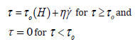
Where τ is the applied shear stress, γ. is the shear rate, η is dynamic viscosity determined by the base fluid composition, and the field-induced shear stress τ0 depends on the magnetic field strength H. Abrasive medium used in this set of experiments consists of 20%vol magnetic particles (of 1200 mesh size), 20%vol silicon carbide powder (of mesh size 1200) and 60%vol base medium (50%wt glycerin and 50%wt liquid paraffin). Base medium combination and their percentage were obtained through study on fluid characteristics, their availability and price and some experimental try and error and as a result, a 1:1 combination of liquid paraffin and glycerin was selected. In order to have equal dispersed particles in the base medium, a special bin with designed fins was used as a mixer to stir the medium. Figure 1 shows mechanism of magnetorheological abrasive flow finishing process.
Figure 1:Mechanism of magnetorheological abrasive flow finishing [28].

A new setup was designed and fabricated for the experiments that has a little difference with previous models and some advantages such as lower fabrication cost, portability and easy workpiece change. In this hydraulic-mechanic set, a hydraulic power unit and a mechanical part with a spring backstroke provide needed pressure in the finishing process. Figure 2a & 2b shows a graphic view of hydraulic and mechanical parts, respectively. Hydraulically actuated cylinders extrude abrasive medium in lower container to finishing space where magnets applying an external magnetic field and after a specific distance heavy spring in mechanical part is pressed and hydraulic cylinder stops electrically so there will be backstroke and this reciprocating motion forms finishing process. Besides, abrasive medium pistons were considered abrasion resistant and durable against finishing pressure. After power unit, to provide magnetic field, two permanent magnets were used at magnetic field strengths of 0.2T, 0.6T and 1T for each independent experiment condition. Abrasive particles in this study were SiC in different mesh size range from 400 to 1200. Jha S & Jain V [27], conducted experiments on flat stainless steel that showed effect of external magnetic field on finishing process efficiency. They reported that an increase in magnetic field strength, from 0 T to 0.574T, causes surface roughness decrease from 0.49μm to 0.34μm. In this study, using previous experiences with a little change, experiments were conducted on austenite stainless steel at magnetic field strengths 0.2T, 0.6T and 1T, abrasive particles in 400, 800 and 1200 mesh size, 30, 45 and 60 minute cycles. Furthermore, used abrasive medium constitutes of 20%vol magnetic particles (of 1200 mesh size), 20%vol silicon carbide (of mesh size 1200) and 60%vol base medium. Magnetic and SiC particles were mixed together in base medium using a special container for stirring the combination. Also [32], have investigated the effect of magnetic field strength and reported the same trend. In other studies by Sankar et al. [46] and Singh et al. [47], they have investigated the effect of rheology and dynamic viscoelasticity of abrasive medium. Kathiresan et al. [48] have investigated modeling and optimization techniques to increase efficiency of MRAFF process. An extensive experimental study has been conducted by Dehghan et al. [26], in order to investigate the effect of workpiece material and composition of abrasive medium.
Figure 2a: Hydraulic power unit
2b: Mechanical backstroke unit.

Results and Discussion
Figure 3:Effect of magnetic field strength on surface quality.

After finishing all pieces with MRAFF, surface roughness was measured with Mahr Surfanalyzer PS1 for each piece to demonstrate effect of finishing parameters on final surface roughness. Initial value for each piece was 0.6-0.7μm. As possible errors in measurement are inevitable using a roughness meter due to probable cross of stylus over deep grooves made through grinding for workpiece preparation, a scanning electron microscopy (SEM) micrograph is provided for each workpiece to ensure measured values.
SEM micrographs are provided in 500×, 1000× and 2000×. After all, because there is no precise scale to measure values using an SEM image, values are set as what stylus measured. Experiments were designed and their values are shown in upcoming graphs. Due to data overlap in different finishing condition, they are divided into three groups. First set of experiments were conducted to show the effect of magnetic field strength. So, this condition was considered among all possible conditions, randomly: abrasive particles in mesh size of 800, finishing time of 45 minutes and magnetic field strengths of 0.2T, 0.6T and 1T. Results are shown in Figure 3 with a following discussion.
As it can be seen in Figure 3, with increase in magnetic field strength, surface roughness increases. To ensure this result, data in other eight conditions from all possible conditions were graphed and the outcomes were the same. Therefore, in general one could say that in finishing process of stainless steel, increase in magnetic field results in rougher surface. Possible reason for this behaviour could be less moving ability of jelly phase in Bingham plastic zone at stronger magnetic fields. In this case, jelly phase coagulates more in the magnetic area and loses its reciprocating motion as it penetrates to the surface due to high magnetic field strength. Another possible reason could be that the medium sticks to the surface of the workpiece firmly and the high hydraulic pressure passes the medium from the center of the finishing component (i.e. tubes) space due to very strong magnetic field adjacent to the workpiece walls. This happens as magnetic and abrasive particles are stuck to the walls close to the magnetic poles. Therefore, in the middle of the workpiece, a central passage appears that abrasive medium passes through and there will be no abrasion on the inner surface of the workpiece. In both of these mechanisms, the abrasive medium does not have effective material removal that causes a less reduction in surface roughness. Second set of experiments were conducted to show effect of abrasive particle mesh size. So, finishing parameters here describe as magnetic field strength of 0.6T, finishing time of 45 minutes, and abrasive particle mesh size of 400, 800 and 1200. Results are shown in Figure 4.
Figure 4:Effect of abrasive particle size on surface quality.

Figure 5:Effect of finishing time on surface quality.

Regarding Figure 4, it is obvious that with increase in mesh size or decrease in particle size, surface roughness comes down and results in a finer surface. Here again to ensure that graph 2 illustrates general behavior of abrasive particle mesh size, all other conditions were examined and in just one condition a little deviation from regular behavior had been observed. In this case, possible reason for this happening could be increase in cutting edges by increase in mesh number. Besides, the greater the abrasive particles, the bigger their cutting edges are, so scratches made by these bigger cutting edges are greater than smaller particles. Therefore, smaller abrasive particles produce a better surface quality. Finally, to examine effect of finishing time cycle, last set of experiments with the following condition has been conducted: Magnetic field strength of 0.8T, abrasive particle mesh size of 400, finishing cycles of 30, 45 and 60 minutes. Results are shown in Figure 5.
Different from other conditions, time effect is not linear. With increase in finishing time from 30 to 45 minutes, surface roughness improves but after this point and with moving toward point 60 minutes, surface roughness increases. This result has been compared with the other possible conditions and there was no significant difference between them but graph slope between these three points. Here in the first part from 30 to 45 minutes, the possible reason could be increase abrasion time and as a result, more peaks are removed. Therefore, surface roughness in this region improves and there will be a finer surface than first. However, in the second part from 45 to 60 minutes, excess abrasion time makes fine surface scratched by continuing abrasion after removal of peaks. However, this conclusion may not be completely true or even may not be the only reason, because abrasive particles will be abraded themselves after such a long period of finishing. Here this hypothesis appears that maybe, probable abrasive particle fracture due to smash through finishing process makes them sharp again and these new sharp cutting edges even in smaller size, continue abrasion and make surface ragged. After investigating these parameters independently, it worth compare them together to get a general layout form their behavior. Figure 6 illustrates their effect on surface roughness in different conditions. Table 1 shows the order of experiments that are shown in Figure 6.
Figure 6:General comparison between different conditions with different finishing parameters.

Table 1:List of experiments.

Besides, SEM micrographs are provided in different magnifications to help estimation of measured values by stylus. In addition, scratches produced during grinding process are obviously visible. It should be mentioned that because workpiece is grinded manually, grinding grooves may not have a regular pattern in pictures but abrasion grooves made by MRAFF are almost parallel. Figure 7 & 8 show workpiece surface structure after different conditions of finishing.
As it could be seen in Figure 7 & 8, finishing condition affects resulted surface. In a highly abrasive condition, surface roughness will decrease but rises again after a specific point; however, if these conditions get closer to the optimized one, a fine surface such as the one in Figure 7 will be obtained. However, if abrasion condition could not beat initial surface roughness occurred due to grinding, porosity or air gaps, because of weak abrasion condition, resulted surface would be similar to Figure 8. In Figure 8, it is obvious that surface is almost fine where porosity does not exist but in porous zone, it is incapable of removing it but only abrade its edge and creates fillet edges of the porosities. In fact, this could not be a deficiency since MRAFF has to remove peaks on a surface. However, the measured surface roughness is an average value of the rough and polished zones and the high values of surface roughness in some regions will increase the average roughness values read by the measurement device.
Figure 7:Workpiece finished with MRAFF at 0.4 T, 1.5hr and mesh size of 400; A) SEM micrograph at 1000× B) SEM micrograph at 2000×, C shows grinding marks and D shows deep abrasive grain marks [27].

Figure 8:1T, 30 minutes and mesh size of 400; A) SEM micrograph at 510×, B) SEM micrograph at 1000×, C) shows abrasive grain marks and D) shows some porosity in base metal [27].

Conclusion
In this study, a new finishing setup for MRAFF has been considered and experiments were conducted under different finishing conditions to show the effect of variable parameters of finishing on final surface quality. It was observed that with increase in magnetic field strength from 0.2T to 1T, gradually, surface roughness rises. However, material removal in some pieces was very negligible. Even in some samples, abrasive particles made increased the surface roughness. In addition, increase in mesh number from 400 to 1200, surface quality inclines to a finer one. This happens due to smoother finishing process via more and smaller cutting edges. Due to measured results, increasing process time from 30 to 45 minutes, surface quality improved but after this point by increase finishing time to 60 minutes, this result was inversed. This happened because in the first region, before optimum point, there was not enough time for abrasive medium to abrade surface well, but after that point, inordinate abrasion scratched the surface rough. Possible particle fracture, also, can affect worsening surface after point 1hr.
References
- El Hofy HAG (2005) Advanced machining processes: Nontraditional and hybrid machining processes. McGraw Hill Professional, USA.
- Bifano TG, Dow TA, Scattergood RO (1991) Ductile-regime grinding: a new technology for machining brittle materials. Journal of Engineering for Industry 113(2): 184-189.
- Zhao W, Meng Q, Wang Z (2002) The application of research on powder mixed EDM in rough machining. Journal of Materials Processing Technology 129(1-3): 30-33.
- Momber AW, Kovacevic R (2012) Principles of abrasive water jet machining. Springer Science & Business Media, Germany.
- Thoe T, Aspinwall D, Wise M (1998) Review on ultrasonic machining. International Journal of Machine Tools and Manufacture 38(4): 239-255.
- Dubey AK, Yadava V (2008) Laser beam machining-a review. International Journal of Machine Tools and Manufacture 48(6): 609-628.
- Taniguchi N (1983) Current status in and future trends of ultraprecision machining and ultrafine materials processing. CIRP Annals 32(2): 573- 582.
- Indge JH (1991) Lapping, honing, and polishing. ASM International, Engineered Materials Handbook 4: 351-359.
- Hassan M, Mehrpouya M, Dawood S (2014) Review of the machining difficulties of nickel-titanium based shape memory alloys. Applied Mechanics and Materials 564: 533.
- Ghoreishi R, Roohi AH, Ghadikolaei AD (2018) Analysis of the influence of cutting parameters on surface roughness and cutting forces in high speed face milling of Al/SiC MMC. Materials Research Express 5(8).
- Dorri MM, Pascale C, Stephane T, Diego M (2018) Enhancing the barrier properties of a fluorocarbon plasma-deposited coating by producing an Interface of amorphous oxide layer on 316L stainless steel for stent applications. Surface and Coatings Technology 347: 209-216.
- Mehdizadeh M, Akbarzadeh S (2016) Experimental investigation and a model to predict the steady-state friction coefficient in the lubricated contact. STLE Vegas, USA.
- Mehdizadeh M, Khonsari M (2018) On the role of internal friction in lowand high-cycle fatigue. International Journal of Fatigue 114: 159-166.
- Akbarzadeh A (2015) Effect of nanoparticles on the running-in behavior in lubricated point contact. STLE Dallas, USA.
- Mehdizadeh M, Saleh A, Kayghobad S, Khonsari MM (2015) Experimental investigation on the effect of operating conditions on the running-in behavior of lubricated elliptical contacts. Tribology Letters 59(1): 1-13.
- Namdari N (2018) Numerical solution for transient heat transfer in longitudinal fins. International Research Journal of Advanced Engineering and Science 3(2): 131-136.
- Mirzababaei S, Filip P (2017) Impact of humidity on wear of automotive friction materials. Wear 376-377: 717-726.
- Majid N, Mohammadian B, Dehghadikolaei A, Alidad S, Abbasi M (2018) A numerical study on two-dimensional fins with non-constant heat flux. International Journal of Scientific Engineering and Science 2(7): 12-16.
- Haghshenas A, Arani AG (2014) Nonlocal vibration of a piezoelectric polymeric nanoplate carrying nanoparticle via Mindlin plate theory.Proceedings of the Institution of Mechanical Engineers, Part C: Journal of Mechanical Engineering Science 228(5): 907-920.
- Mortezavim V (2016) Fatigue analysis of metals using damping parameter. International Journal of Fatigue 91: 124-135.
- Ghorbanpour AA, Haghshenas A, Amir S, Mozdianfard MR, Latifi M, et al. (2013) Electro-thermo-mechanical response of thick-walled piezoelectric cylinder reinforced by boron-nitride nanotubes. Strength of Materials 1: 140-158.
- Brooks AJ, Daniel SH, Hong Y, Haghshenas A, Jumao Y, et al. (2018) Neutron interferometry detection of early crack formation caused by bending fatigue in additively manufactured SS316 dogbones. Materials & Design 140: 420-430.
- Haghshenas A, Khonsari M (2018) Damage accumulation and crack initiation detection based on the evolution of surface roughness parameters. International Journal of Fatigue 107: 130-144.
- Davoodi B, Eskandari B (2015) Tool wear mechanisms and multiresponse optimization of tool life and volume of material removed in turning of N-155 iron-nickel-base superalloy using RSM. Measurement 68: 286-294.
- Davoodi B, Eskandari B (2015) Investigation of wear mechanisms and tool life in turning of N-155 iron-nickel-base superalloy using response surface methodology. Modares Mechanical Engineering 14(15): 51-58.
- Dehghan GA, Vahdati M (2015) Experimental study on the effect of finishing parameters on surface roughness in magneto-rheological abrasive flow finishing process. Proceedings of the Institution of Mechanical Engineers, Part B: Journal of Engineering Manufacture 229(9): 1517-1524.
- Jha S, Jain VK (2004) Design and development of the magnetorheological abrasive flow finishing (MRAFF) process. International Journal of Machine Tools and Manufacture 44(10): 1019-1029.
- Jain V, Adsul S (2000) Experimental investigations into abrasive flow machining (AFM). International Journal of Machine Tools and Manufacture 40(7): 1003-1021.
- Kaufmana FB, Thompsonb DB, Broadieb RE, Jasoa MA, Guthrie WL, et al. (1991) Chemical‐mechanical polishing for fabricating patterned W metal features as chip interconnects. Journal of the Electrochemical Society 138(11): 3460-3465.
- Mori Y, Yamauchi K, Endo K (1987) Elastic emission machining. Precision Engineering 9(3): 123-128.
- Ibrahim H (2018) In vitro corrosion assessment of additively manufactured porous NiTi structures for bone fixation applications. Metals 8(3): 164.
- Fotovvati B (2018) A Review on melt-pool characteristics in laser welding of metals. Advances in Materials Science and Engineering, Hindawi Publishing Corporation, Egypt.
- Somayeh P, Milad G, Sunil B, Harish I, Sundar VA, et al. (2018) Effects of atomizing media and post processing on mechanical properties of 17-4 PH stainless steel manufactured via selective laser melting. Additive Manufacturing 22: 127-137.
- Dehghan A (2018) Additive manufacturing as a new technique of fabrication. Journal of 3D Printing and Applications 1(1): 3-4.
- Shinmuraa T, Takazawab K, Hatanoc E, Matsunagac M, Matsuo T, et al. (1990) Study on magnetic abrasive finishing. CIRP Annals 39(1): 325- 328.
- Komanduri R, Jiang M (1999) Magnetic float polishing processes and materials therefor. Google Patents.
- Kordonski WI, Jacobs S (1996) Magnetorheological finishing. International Journal of modern physics B 10(23-24): 2837-2848.
- Dehghan A, Ansary J, Ghoreishi R (2018) Sol-gel process applications: A mini-review. Proc Nat Res Soc 2: 02008.
- Dehghan A (2018) Enhance its corrosion behavior of additively manufactured NiTi by micro-arc oxidation coating. University of Toledo, USA.
- Namdari N, Dehghan A (2018) Natural frequencies and mode shapes for vibrations of rectangular and circular membranes: A numerical study. International Research Journal of Advanced Engineering and Science 3(2): 30-34.
- Dehghan A, Navid N, Behrouz M, Seyed RG (2018) Deriving one dimensional shallow water equations from mass and momentum balance laws 5(6): 408-419.
- Eskandari B, Davoodi B, Ghorbani H (2018) Multi-objective optimization of parameters in turning of N-155 iron-nickel-base superalloy using gray relational analysis. Journal of the Brazilian Society of Mechanical Sciences and Engineering 40: 233.
- Davoodi B, Eskandari B (2015) Surface roughness optimization in machining of N-155 iron-nickel-base superalloy using the taguchi method. Aerospace Mechanics Journal 11(2-40): 43-53.
- Wang CA, Lee S (2009) Study the characteristics of magnetic finishing with gel abrasive. International Journal of Machine Tools and Manufacture 49(14): 1063-1069.
- Kamath GM, Wereley NM (1997) A nonlinear viscoelastic-plastic model for electrorheological fluids. Smart Materials and Structures 6(3): 351.
- Sankar MR, Jaina VK, Ramkumara J, Joshi YM (2011) Rheological characterization of styrene-butadiene based medium and its finishing performance using rotational abrasive flow finishing process. International Journal of Machine Tools and Manufacture 51(12): 947- 957.
- Sachin S, Deepu K, Ravi SM, Jain VK (2018) Viscoelastic medium modeling and surface roughness simulation of microholes finished by abrasive flow finishing process. The International Journal of Advanced Manufacturing Technology, pp. 1-18.
- Kathiresan S, Mohan B (2018) Experimental analysis of magneto rheological abrasive flow finishing process on AISI stainless steel 316L. Materials and Manufacturing Processes 33(4): 422-432.
© 2018 Amir Dehghanghadikolaei. This is an open access article distributed under the terms of the Creative Commons Attribution License , which permits unrestricted use, distribution, and build upon your work non-commercially.
Editor In Chief


.jpg)


Signup for Newsletter

Quick Links
 Editorial Board Registrations
 Submit your Article
 Refer a Friend
 Advertise With Us
Our Recent Edition

.jpg)


Top Editors


.jpg)


.bmp)
.jpg)
.png)
.jpg)


.jpg)


.png)

.png)


.png)


Financial Support

Sponsors

Latest e-Books

Latest Video

 a Creative Commons Attribution 4.0 International License. Based on a work at www.crimsonpublishers.com.
Best viewed in
a Creative Commons Attribution 4.0 International License. Based on a work at www.crimsonpublishers.com.
Best viewed in