- Submissions

Full Text
Research & Development in Material Science
Influence of Titanium Oxide on Structure, Corrosion and Soldering Properties of Sn82Bi15Zn3 Alloy
Abu Bakr El-Bediwi* and Reham Samir
Department of Physics, Mansoura University, Egypt
*Corresponding author: Abu Bakr El-Bediwi, Department of Physics, Metal Physics Lab, Faculty of Science, Mansoura University, Egypt
Submission: March 28, 2018;Published: May 14, 2018

ISSN: 2576-8840
Volume6 Issue1
Abstract
Our work study the effect of titanium oxide on structure, soldering properties such as melting temperature, wetting process and corrosion behavior of Sn82Bi15Zn3 alloy. Microstructure of Sn82Bi15Zn3 alloy changed after adding different ratio from titanium oxide. Lattice microstrain of Sn82Bi15Zn3 alloy varied (increased) after adding titanium oxide. Melting temperature of Sn82Bi15Zn3 alloy varied after adding Ti2O. Sn81.4Bi15Zn3(Ti2O)0.6 alloy has low melting temperature. The contact angle Sn82Bi15Zn3 alloy decreased after adding different ratio from titanium oxide. Corrosion resistance of Sn82Bi15Zn3 alloy varied (increased) after adding Ti2O. From our results, soldering properties (melting temperature and contact angle) and corrosion resistance of Sn82Bi15Zn3 alloy improved after adding Ti2O.
Keywords: High tin alloy; Ti2O; Corrosion; Contact angle; Melting temperature
Introduction
Soldering is a low temperature metallurgical joining process. In electronics applications low temperature and reversibility are especially important because of the materials involved and the necessity for reworking and making engineering changes. Solder joining is a wetting process followed by a chemical reaction. Wettability is a function of the materials to be joined, with Cu, Ni, Au, and Pd, as well as alloys rich in one or more of these metals, being particularly amenable to soldering. The chemical reaction following wetting is between the molten solder and the joining metallurgy to form an intermetallic phase region at the interface. Microstructure, wettability and physical properties of Sn96-xZn4Bix alloys are reported by El-Bediwi et al. [1]. The melting temperature of Sn96Zn4 alloy decreased after adding bismuth. But contact angle of Sn96Zn4 alloy varied after adding bismuth. Adding silver caused a significant increase in bismuth-tin-zinc alloy strengthens with a little decreased in melting temperature [2]. El-Bediwi et al. [2] reported that, there is a significant decrease in melting temperature of bismuth-tin-zinc alloy with a very little increase in strengthens after adding indium. Microstructure, thermal parameters, wettability and electrochemical corrosion process of Bi30Sn50Sb10A15Zn3Cu2, Bi25Sn61Sb5Zn4Al3Ag2, and Bi20Sn60Sb7A15Zn3Cd3Cu2, alloys have been studied [3]. Microstructure, wettability behavior, corrosion parameters, thermal properties of quaternary bismuth- tin based alloy have been investigated using different experimental techniques and the results show that, some properties of Bi60Sn40 alloy improved after adding Sb-Zn or Sb-Ag elements [4]. Tin- zinc eutectic alloy has been considered as a candidate for lead free solder materials because of its low melting point, excellent mechanical properties and low cost [5-7]. Mostly solders are based on Sn-containing binary and ternary alloys. Several elements have been selected as alloying elements such as Zn, Bi, Cu, Ag, Sb and so on [8-10]. Specific researchers [11-15] reported that, tin- zinc eutectic solder alloy is poor wettability, reliability, strength, easy oxidation and microvoid formation. To avoid these disadvantages or improve the properties of it, they added minor amount of Bi, Cu, In, Ag, Al, Ga, Sb, Cr, Ni, Ge elements to develop ternary and even quaternary Pb free alloys. The aim of our work was to study the effect of titanium dioxide on microstructure, soldering properties and corrosion of tin bismuthzinc alloy.
Material and Methods
High purity (tin, bismuth and zinc) metal and titanium dioxide (white color) are used to prepare Sn82Bi15Zn3(Ti2O)x (x=0,0.3,0.6,0.9 and 1.2) alloys. These alloys (mixed metals and Ti2O by weight percentage) are melted then normal casted on substrate in air. The samples from alloys are prepared in convenient shape for all tests such as microstructure, thermal parameters, wettability and corrosion behavior. Microstructure of used alloys was performed using Shimadzu X-ray Diffractometer, (Dx-30, Japan) Cu–Ka radiation with l=1.54056 Å at 45kV and 35mA and Ni–filter, in the angular range 2q ranging from 0 to 100° in continuous mode with a scan speed 5deg/min and scanning electron microscope (JEOL JSM-6510LV, Japan). The polarization studies were performed using Gamry Potentiostat/Galvanostat with a Gamry framework system based on ESA 300. Gamry applications include software DC105 for corrosion measurements and Echem Analyst version 5.5 software packages for data fitting. The differential scanning calorimetry (DSC) thermographs were obtained by Universal V4. 5A TA instrument with heating rate 10k/min in the temperature range 0-400 oC.
Results and Discussion
X- ray diffraction analysis
Figure 1: x-ray diffraction patterns of Sn82-xBi15Zn3(Ti2O)x alloys.
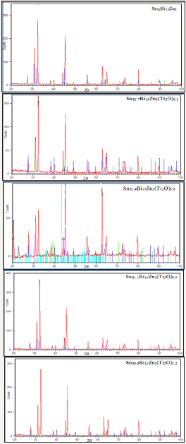
Figure 2: FWHM versus 4tanθ for Sn82-xBi15Zn3(Ti2O)x alloys. alloys.
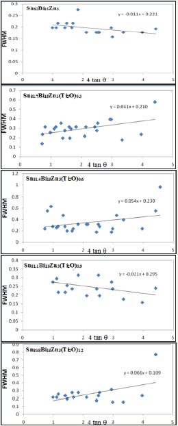
Table 1: x-ray diffraction patterns of Sn82-xBi15Zn3(Ti2O)xalloys.

Table 2: Lattice microstrain of Sn82-xBi15Zn3(Ti2O)x alloys.

X-ray diffraction patterns, Figure 1, of Sn82Bi15Zn3(Ti2O)x (x=0.3,0.6,0.9 and 1.2) alloys have lines corresponding to tetragonal β-Sn phase, hexagonal Bi phase, Zn phase with undetected Ti2O or intermetallic compounds and solid solution from dissolved atoms changed its matrix structure. The details of x-ray analysis such as the peak intensity (crystallinity), peak broadness (crystal size) and peak position (orientation) of Sn82Bi15Zn3 alloy changed after adding different ratio of titanium dioxide as listed in Table 1. That is because Ti2O nanoparticles formed undetected intermetallic compounds with dissolved atoms in matrix alloy. Lattice microstrain, ԑ, which determined from the relation between full width half maximum, FWHM, and 4tan using Williamson and Hall equation [15] is presented in Figure 2. Lattice microstrain of Sn82Bi15Zn3 alloy varied (increased) after adding titanium dioxide as listed in Table 2.
Scanning electron microscope analysis (SEMA)
Figure 3a: SEM of Sn82Bi15Zn3 alloy.
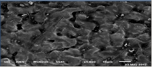
Figure 3b: SEM of Sn81.7Bi15Zn3(Ti2O)0.3 alloy.
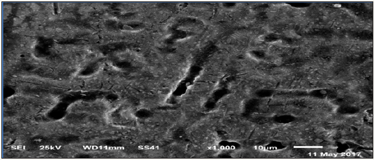
Figure 3c: SEM of Sn81.4Bi15Zn3(Ti2O)0.6 alloy.
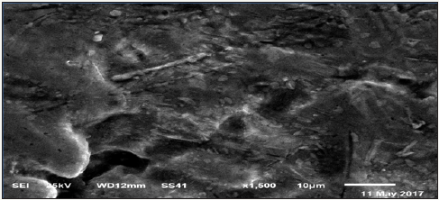
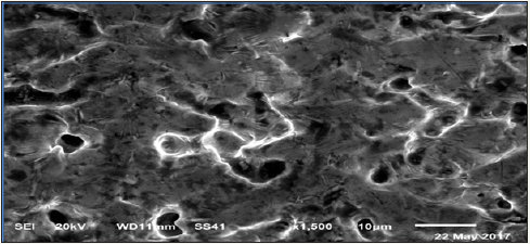
Scanning electron micrographs (SEM) of Sn82Bi15Zn3(Ti2O) x (x=0,0.3,0.6,0.9 and 1.2) are shown in Figure 3a-3e. SEM of Sn82Bi15Zn3 alloy has lamellar structure (tin phase is a gray color, bismuth phase is a black color) contained white color (which is zinc or bismuth-tin or cluster from dissolved atoms) with different shape and size. Sn81.7Bi15Zn3(Ti2O)0.3 alloy has homogenous structure from tin phase (gray color), slabs and spherical shape from bismuth phase (black color) and little spherical grain or around slab from undetected phases (white\or gray) such as zinc or Ti2O or intermetallic phases. Sn81.4Bi15Zn3(Ti2O)0.6 alloy has heterogeneous structure formed from tin phase as a gray color contained bismuth phase as black color and little spherical with slab at grain boundary of undetected phases (zinc or Ti2O or intermetallic phases) as gray/ or white color. Sn81.1Bi15Zn3(Ti2O)0.9 alloy has heterogeneous matrix structure (slabs and spherical with different size\ orientation) as gray color contained lamellar structure bismuth phase as black color and undetected phases (spherical/ around grains) as gray or white color. Sn80.8Bi15Zn3(Ti2O)1.2 alloy has heterogeneous matrix structure of tin phase (gray color) contained spherical bismuth phase (black color) surround by white\or gray color as zinc or Ti2O or intermetallic phases. From SEMA, adding Ti2O to Sn82Bi15Zn3 alloy caused a change in its matrix microstructure (quantity, size and orientation of formed phases).
Figure 3d: SEM of Sn81.1Bi15Zn3(Ti2O)0.9 alloy.
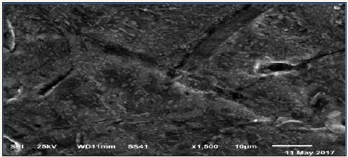
Figure 3e: SEM of Sn80.8Bi15Zn3(Ti2O)1.2 alloy.
Solder properties
Figure 4a: DSC graph of Sn82Bi15Zn3 alloy.
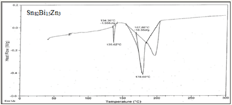
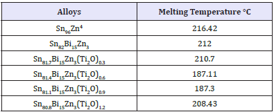
Solder alloys are characterized by the melting temperature being a strong function of composition. Differenitional scanning calometric graphs of Sn82Bi15Zn3(Ti2O)x (x=0,0.3,0.6,0.9 and 1.2) alloys which have more peaks (related more phases) are shown in Figure 4a-4e. Adding titanium dioxide caused a change in DSC shape, intensity and broadness of Sn82Bi15Zn3 alloy like x-ray diffraction patterns. That is because Ti22O changed matrix alloy microstructure such as formed phases and atoms dissolved formed a cluster of atoms or solid solution. Melting temperature of Sn82Bi15Zn3 alloy varied after adding Ti2O as listed in Table 3. Sn81.4Bi15Zn3(Ti2O)0.6 alloy has low melting temperature.
Figure 4b: DSC graph of Sn81.7Bi15Zn3(Ti2O)0.3 alloy.
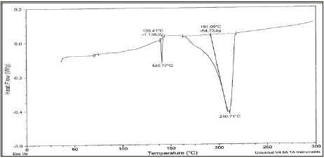
Figure 4c: DSC graph of Sn81.4Bi15Zn3(Ti2O)0.6 alloy.
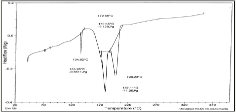
Figure 4d: DSC graph of Sn81.1Bi15Zn3(Ti2O)0.9 alloy.
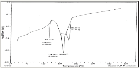
Figure 4e: DSC graph of Sn80.8Bi15Zn3(Ti2O)1.2 alloy.
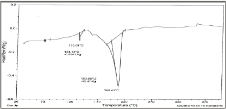
Table 3: Lattice microstrain of Sn82-xBi15Zn3(Ti2O)x alloys.
The contact angle Sn82Bi15Zn3 alloy decreased after adding different ratio from titanium dioxide as presented in Table 4. That is meant, the spreading of molten Sn82Bi15Zn3 alloy increased in copper surface substrate.
Table 4: Contact angles of Sn82-xBi15Zn3(Ti2O)x alloys

Corrosion behavior
Figure 5: Electrochemical polarization curves of Sn82-xBi15Zn3(Ti2O)x alloy.
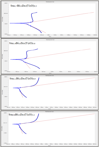
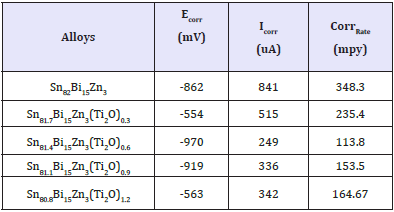
Electrochemical polarization curves of Sn82Bi15Zn3(Ti2O)x (x=0.3,0.6,0.9 and 1.2) alloys in 0.25M HCl are shown in Figure 5. They show, the corrosion potential of used alloys exhibited a negative potential. Also the cathodic and the anodic polarization curves showed similar corrosion trends. The corrosion potential (ECorr), corrosion current (ICorr) and corrosion rate (CorrRate) of Sn82Bi15Zn3(Ti2O)x alloys are presented in Table 5. Corrosion rate and corrosion current of Sn82Bi15Zn3 alloy decreased (varied) after adding Ti2O. That is because adding different ratio of Ti2O caused formed new phases and cluster of atoms or solid solution which effects on atoms segregation and their reactivity with HCl. We recommended to study the effect of Ti2O from 0.1 to 0.9 with 0.1 step.
Table 5: Corrosion parameters of Sn82-xBi15Zn3(Ti2O)x alloys.
Conclusion
1. Adding Ti2O to Sn82Bi15Zn3 alloy caused a change in its matrix microstructure (crystallinity, size and orientation of formed phases in matrix).
2. Lattice microstrain of Sn82Bi15Zn3 alloy varied (increased) after adding titanium dioxide.
3. Melting temperature of Sn82Bi15Zn3 alloy varied (decreased) after adding Ti2O.
4. The contact angle Sn82Bi15Zn3 alloy decreased after adding different ratio from titanium dioxide.
5. Corrosion rate of Sn82Bi15Zn3 alloy decreased (varied) after adding Ti2O.
6. Soldering properties such as melting temperature and spreading (contact angle) of Sn82Bi15Zn3 alloy improved and very closed to lead- tin commercial solder alloy (M.P=183 o C and contact angle o 19) after adding Ti2O.
7. Corrosion resistance of Sn82Bi15Zn3 alloy also is improved by adding Ti2O.
References
- El-Bediwi AB, El-Shafei A, Kamal M (2015) Microstructure, physical and soldering properties of Tin-Zinc-Bismuth alloy. MSAIJ 12(2): 2-28.
- El-Bediwi AB, Dawood F, Kamal M (2015) Effect of quaternary addition on structure, electrical, mechanical and thermal properties of bismuthtin- zinc rapidly solidified fusible alloy. Journal of Advances in Physics 7(3): 1952-1958.
- El-Bediwi AB, Bader S, Khalifa F (2016) Microstructure, electrochemical corrosion behavior and soldering properties of hexa and hepta bismuthtin based alloy. Global Journal of Physics 4(3): 480-495.
- El-Bediwi AB, Bader S, Khalifa F (2016) Effect of Alloying Elements on Electrochemical Corrosion Behavior, Microstructure, Wettability and Thermal Performance of Bismuth-Tin Based Alloys. IJSRSET 2(2): 1267- 1277.
- Yang W, Messler RW (1994) Microstructure evolution of eutectic Sn-Ag solder joints. J Electron Mater 23(8): 765-772.
- Mavoori H, Chin J, Vaynman S (1997) J Electron Mater 41: 1269.
- McCormack M, Jin S, Kammlott DGW (1995) Proceedings of the 1995 IEEE international symposium on electronics and the environment, ISEE, Orlando, FL, USA, pp. 1-3 171.
- Abtew M, Selvaduray G (2000) Lead-free solders in microelectronics. Mater Sci Eng Rep 27(5-6): 95-141.
- Vincent JH, Humpston G (1994) GEC J Res 11: 76.
- Harrison MR, Vincent JH, Steen HAH (2001) Sold Surf Mount Technol 13: 21.
- Kim KS, Yang JM, Yu CH, Jung IO, Kim HH (2004) Analysis on interfacial reactions between Sn-Zn solders and the Au/Ni electrolytic-plated Cu pad. J Alloy Compd 379: 314.
- Anderson IE, Foley JC, Cook BA, Harringa J, Terpstra RL, et al. (2001) J Electron Mater 30(9): 1050.
- McCormack M, Jin S, Kammlott GW, Chen HS (1993) New Pb‐free solder alloy with superior mechanical properties. Appl Phys Lett 63(15).
- Miric AZ, Grusd A (1998) Lead‐free alloys. Surf Mount Technol 10(1): 1-19.
- Williamson GK, Hall WH (1953) X-ray line broadening from filed aluminium and wolframL’elargissement des raies de rayons x obtenues des limailles d’aluminium et de tungsteneDie verbreiterung der roentgeninterferenzlinien von aluminium- und wolframspaenen. Acta Metallurgy 1(1): 22-31.
© 2018 Abu Bakr El-Bediwi. This is an open access article distributed under the terms of the Creative Commons Attribution License , which permits unrestricted use, distribution, and build upon your work non-commercially.
 a Creative Commons Attribution 4.0 International License. Based on a work at www.crimsonpublishers.com.
Best viewed in


.jpg)


 Editorial Board Registrations
 Submit your Article
 Refer a Friend
 Advertise With Us
.jpg)


.jpg)


.bmp)
.jpg)
.png)
.jpg)


.jpg)


.png)

.png)


.png)


